
Abstract
Design of shrink-fit tool holders requires fast reliable stress analysis (from operational point of view). However, such an analysis exhibits difficulties due to its nonlinear nature. This article shows how to execute a complete cycle of design analysis iteration utilizing finite element analysis approach. Each finite element analysis cycle of iteration requires both transient thermal and structural coupled analyses. For a particular initial design, the transient heating of shrink-fit holder is first simulated, that is, the tool inner diameter hole expands due to inductive heating from its nominal value, so that cutting tool is easily inserted. Following this, both tool holder and cutting tool are allowed to cool down so that shrink-fit design forms a uniform contact pressure distribution. Finally, cutting tool is fixed at the contact interface. Then, the tool assembly is rotated (for testing) up to a cutting speed of 40,000 r/min, where transmission torque is also calculated to assess design limits for safe/efficient torque transmission. All of these analyses complete a single design cycle of iteration of the shrink-fit tool holder. Results presented include the calculation of change in shrink-fit pressure values over preload and preload + spin cases. Further assessment is also made to make sure overall elastic equivalent stresses at maximum operating speed are below yield limit of the tool holder material used in the design.
Keywords
Introduction
Shrink-fit method is known as one of the common ways of coupling a hub (i.e. tool holder) to a shank (i.e. cutting tool) for torque transmission and is widely used in many manufacturing applications (i.e. for high-speed milling). Diametric differences of both tool holder contact hole (initially hot) and tool shank create a required contact locking pressure when shrink-fit is done. After cooling down of both components, an elastic deformation takes place resulting in normal and frictional forces (i.e. an effective pressure formation) at contact interfaces. In the literature, some past works studied elastic structural deformations on shrink-fit design utilizing finite element analysis (FEA).1,2 In addition, high-speed milling operations, that is, tool holder interface dynamics,3,4 shrink-fit holder connection stiffness/damping modeling for frequency response modeling and radial grip rigidity are also studied5,6 using analytical and FEA-based calculations.
Shrink-fit tool holders offer improved advantages with their high precision and fast cutting tool changing capabilities in machining with increased efficiency from both operational and cost point of views. In addition, they provide higher concentricity and uniform clamping force than conventional tool adapters. Shrink-fit-generated pressure distribution at contact interface provides high transmission torque even at high speeds without imbalance or spun of the cutting tool. But all of these advantages are not without challenges, that is, all shrink-fit operations need to be designed in more detail, and precision so that shrink-fit tool holders can be operated safely and efficiently as intended. These aforementioned qualities come with the cost of pin-pointed design and analysis of such shrink-fit tool geometries.
This article studies shrink-fit concept from initial design to final design analysis phase and presents comprehensive insight into determining both thermal transient and transient structural (with friction) behaviors of the tool assembly, thus enabling shrink-fit tool designers to incorporate computer-aided engineering (CAE) in their companies for fast and reliable design evaluation of such a system. For this purpose, a single cycle of FE-based design analysis iteration is illustrated in Figure 1.
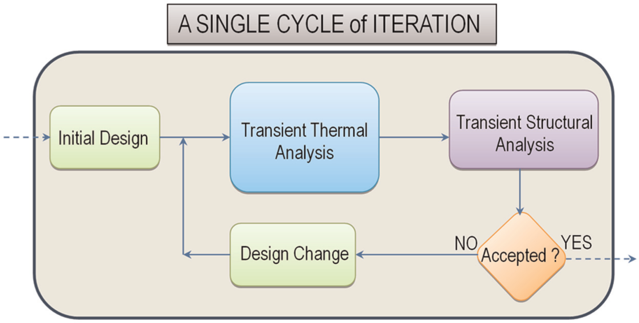
FEA-based single cycle of design analysis iteration.
In this study, a test bed design is studied on a sample shrink-fit tool holder as shown in Figure 2. Steps of shrink-fit procedure between the tool holder and cutting tool is rather well established7–10 and briefly presented in the following four steps.
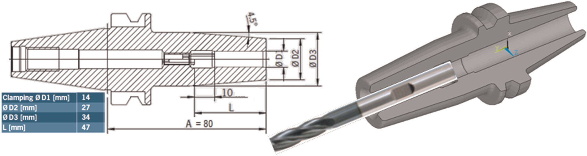
2D 11 /3D shrink-fit tool holder and cutting tool.
Step 1: Initial design of shrink-fit tool holder. Along with other geometric considerations, tool holder contact diameter hole (i.e. slightly smaller than cutting tool’s shank diameter) is designed for shrink-fit procedure with appropriate interference. Note that the cutting tool shank diameter is always given with standard dimensions in the industry. The value of the diametrical interference can be taken as

where d represents shank diameter of cutting tool. The friction between the tool holder and cutting tool interface creates/controls the translational and rotational behaviors of the contact. An approximate value for friction coefficient of dry steel contact is used as µ = 0.2. The reader should note that this is a mean value frequently used in the literature,6,7,12,13 and Hanqing et al. 12 and Xu 13 also introduce analytical formulations/calculations for approximate value of µ used in this study.
Step 2: Heat the shrink-fit tool holder. At this stage, shrink-fit tool holder is heated for 5–10 s so that cutting tool holder inner hole diameter expands from its nominal value and becomes larger than that of cutting tool shank diameter. Now cutting tool can be easily inserted.
Step 3: Cool down the shrink-fit tool holder. At this stage, in about 60 s, the whole system is cooled down and shrink-fit forms. Resulting pressure distribution at interface is utilized to transmit the sufficient torque so that material removal could take place. Similarly, this process can be reversed for cutting tool removal from tool holder and left out of scope of this work.
Step 4: Rotate the cutting tool for material removal. At this stage, up to 40,000 r/min of cutting speeds can be reached while maintaining enough transmission torque for cutting operation. Therefore, this stage is very critical in determining the shrink-fit interference and critical maximum speed to maintain safe contact pressure. Centrifugal forces (Fcent.) acting on a body increase with angular velocity (ω) in the order of 2 as shown in the following equation
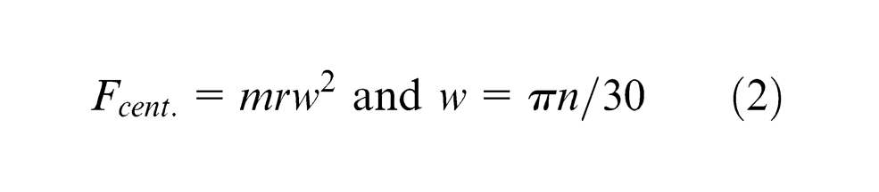
If contact pressure is kept well above safe level at high cutting speeds (n), then cutting tool can operate safely (spun shank is avoided), thus allowing for an efficient machining conditions. The challenge in designing shrink-fit adaptor is highly related to precise calculation of contact forces and their distribution for preload (where only tool assembly forces are considered) and preload + spin (where both preload and overall spin forces are considered) cases. Calculation of overall elastic stresses for shrink-fit tool holder is also important for strength considerations because traditional analytic models are rather inaccurate for these cases due to complexity of the problem. Therefore, there is an emergent need for FEA solutions. For this purpose, an adopted FEA procedure is presented in the following section.
FEA procedure
Two-dimensional (2D) axisymmetric finite element model used in this study consists of two meshed parts (i.e. shrink-fit tool holder and cutting tool), as shown in Figure 3. Tool holder is heated to allow for thermal expansion at inner hole diameter. Thermal transient FE analysis could simulate this time-dependent process, and this loading is performed by applying heat generation on the outer surface of tool holder (where induction heating occurs). After running the FE model, nonuniform temperature distribution on the tool holder can be obtained. Following this, the structural analysis (which is fully coupled with thermal analyses) is run to calculate radial contact pressure forces and elastic equivalent stresses for first preload and following preload + spin cases, as detailed in the next sections.
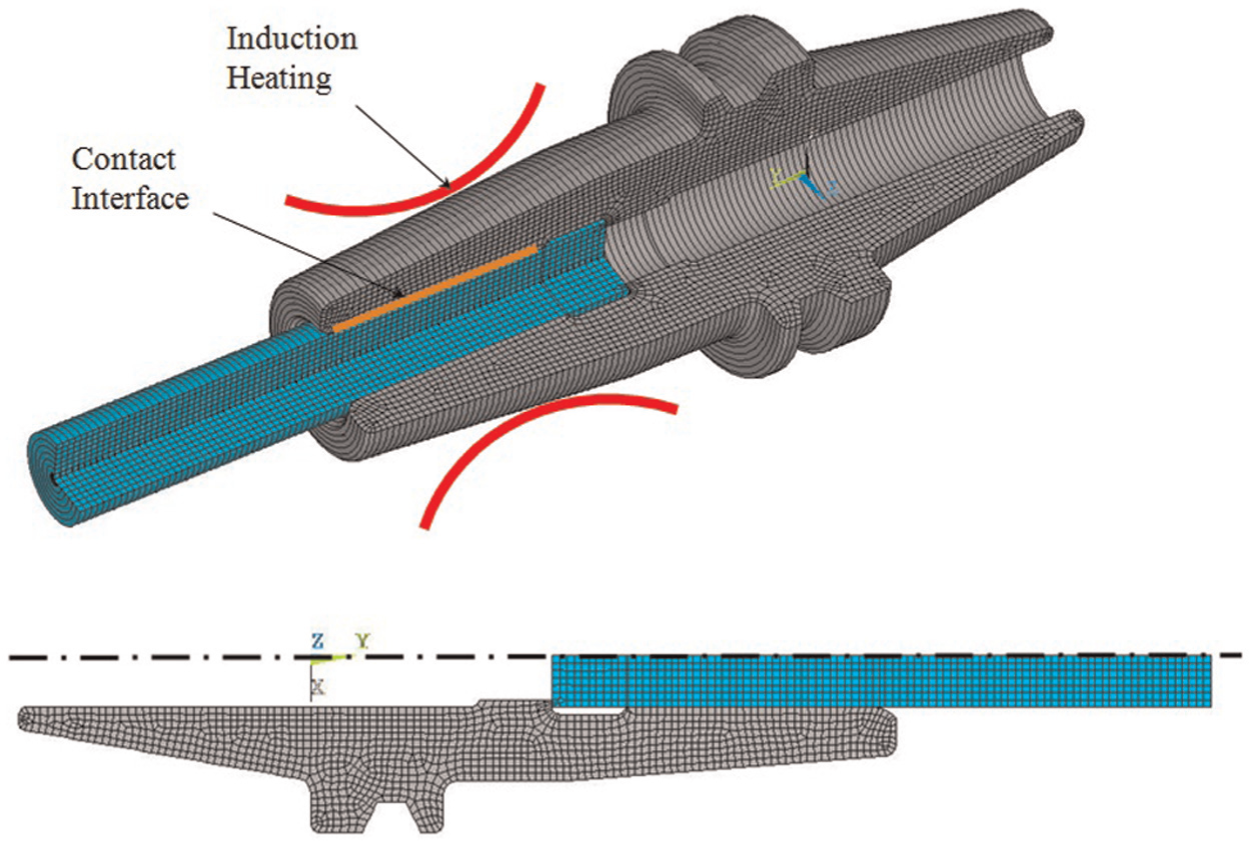
2D axisymmetric FE mesh with induction heating.
Thermal model
An axisymmetric finite element model representing the tool holder with appropriate interference to a cutting tool is created as presented in Figure 3. Tool holder is meshed with E = 1211 elements having N = 1352 nodes, and cutting tool is meshed with E = 748 elements having N = 748 nodes. A fixed heat generation to outer portions of the tool holder, as shown in Figure 3, is applied to simulate the induction heating. In the proposed FE analyses, from T = 0 to 7 s fast heating and consequently from T = 7 to 60 s rapid cooling phase of the whole heat transfer phenomenon is considered, and the following assumptions are made in the solution:
Sufficient heating to the tool holder is assumed through induction heating at a location shown in Figure 3.
The heat loss from tool holder and cutting tool to the environment is neglected since the heat loss occurs in a short time span. Therefore, all noncontact surfaces in FE model are assumed to be adiabatic, and an initial condition of room temperature (20 °C) is assumed.
Only tool holder is heated and cutting tool is taken at room temperature.
Some minor geometry simplifications are done for axisymmetric representation of the whole model.
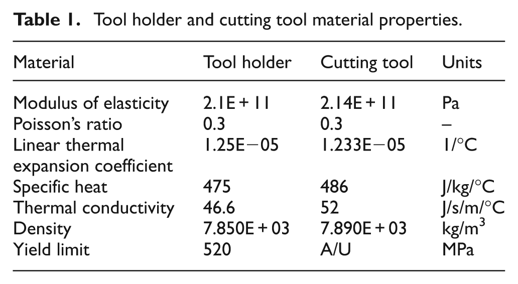
ANSYS®, 14 a-multipurpose FEA code, is used in the creation of cutting tool geometry, meshing, model setup and for all analyses. The 2D axisymmetric thermal FE model is meshed with ANSYS Plane55 elements. No contact is modeled at the interface since the tool holder is heated alone. Material properties used in all FEAs are presented in Table 1.
Tool holder and cutting tool material properties.
A thermal transient heat transfer solution is obtained at time intervals of T = 0–7 s (heating) and 60–0 s (cooling). Initially, at T = 0.1E−05 s, model is at 20 °C room temperature and no heat is applied to the model. From T = 0.1E−05 to 7 s, an instantaneous heat generation is applied to the tool holder, and resulting thermal transient nonuniform temperature distribution is obtained at 12 cumulative iterations. From time T = 7 to 60 s, rapid cooling is performed, and all assemblies come down to room temperature at 59 cumulative iterations. Temperature distribution plots at both T = 0.1E−05 and T = 7 s are presented in Figure 4.
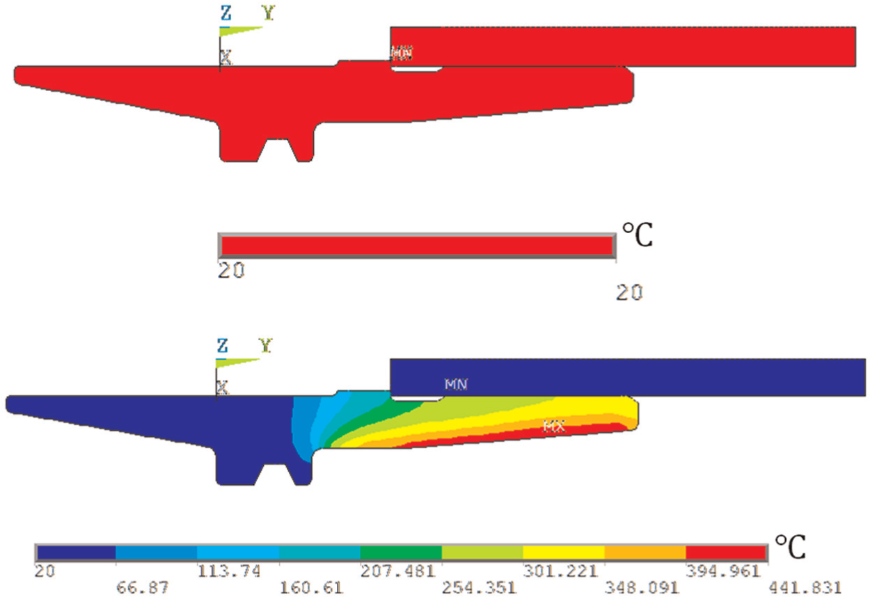
Overall temperature distribution at T = 0.1E−05 and T = 7 s.
As it is observed from the thermal results at T = 0.1E−05 s, the whole assembly is at room temperature of 20 °C, and starting at this time, the tool holder is warmed up, and overall temperature distribution on the tool holder reaches up to 442 °C at the tool holder outer surface. Very high temperature gradient from heat application surface toward the inner diameter hole is formed. Finally, the tool holder hole diameter expands. After cutting tool insertion, from T = 7 to 60 s, now heating is replaced by rapid cooling so that tool holder inner diameter hole (which shrinks) and cutting tool shank form interference (at a nominal diameter at room temperature), which produces a large radial forces at the contact surface and fixes tool holder and cutting tool together for torque transmittal. Temperature distribution along the contact interface on the tool holder inner diameter hole is also plotted in Figure 5.
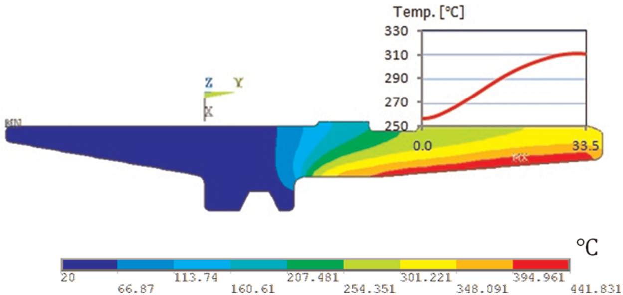
Temperature distribution at contact interface of tool holder at T = 7 s.
In the next section, these temperature solutions are mapped onto structural FE model for coupled transient structural analysis. First, initial contact pressure distribution and its magnitude are both calculated in the preload case. Then, the whole system is rotated up to 40,000 r/min for further investigation to determine whether interface contact pressure goes below a safe locking level due to spinning effects.
Structural model
A thermal axisymmetric FE model is converted to structural FE model by changing thermal element types into structural element ones. All boundary conditions are redefined to be used in the structural analysis. In the structural model, ANSYS Plane42, 2D axisymmetric elements are used. Tool holder and cutting tool are both held fixed at symmetry axis and axially to prevent rigid body motion. Surface-to-surface contact elements are used to model the contact between tool holder and cutting tool (δ = interference). Before going into further details of this analysis, the validation of the present FE model is explored in the following section.
FE model validation
The interference fit between tool shank and tool holder is a highly nonlinear elastic contact problem, including the nonbasic problem geometry, yet very difficult to solve by conventional contact mechanics. Therefore, finite element modeling and simulation are performed to analyze the relationship between interference and contact pressure value so that resulting stress levels are used in the design. However, for a specific condition and assumptions, we can validate the FEA results numerically. For the preload condition (where friction coefficient of µ = 0) and assuming two cylindrical parts are shrink-fitted upon another, the interface pressure p, the tangential (hoop) stress at the shrink-fit radius of the tool
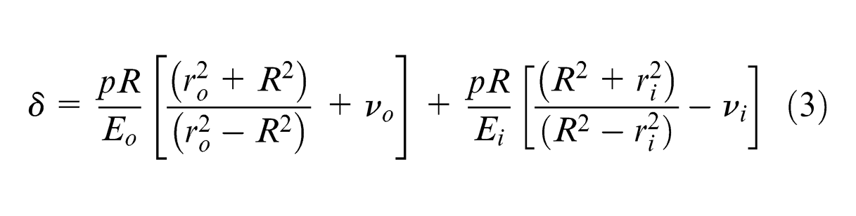
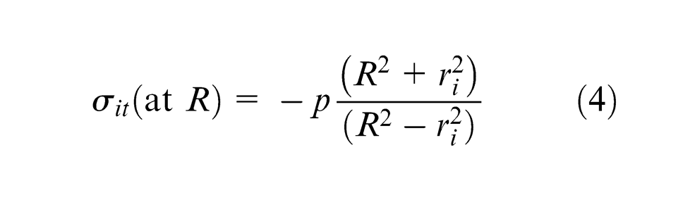
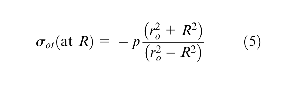
where Eo and νo are modulus of elasticity and Poisson’s ratio of the tool holder, respectively; Ei and νi are modulus of elasticity and Poisson’s ratio of the tool, respectively; δ is radial interference; R is shrink-fit radius; ri is inner hole radius of tool shank; and ro is outer radius of tool holder. Using δ = 0.007 mm, Eo = 2.1E05 N/mm2, Ei = 2.14E05 N/mm2, νo = νi = 0.3, R = 7 mm, ri = 0 mm and ro = 7 mm values, we obtain p = 88 N/mm2,
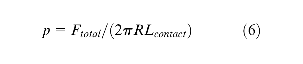
This specific condition presented above corresponds to preload case which is solved for µ = 0 for FE model verification purposes only. Overall, FE model results for both nodal contact forces (loads) and Ftotal are presented in Table 2. Total contact pressure p is then obtained by dividing Ftotal by contact surface area. Finally, we can calculate p = 90.8 MPa, using equation (6), where
Nodal forces at the contact interface for FE model validation (N).
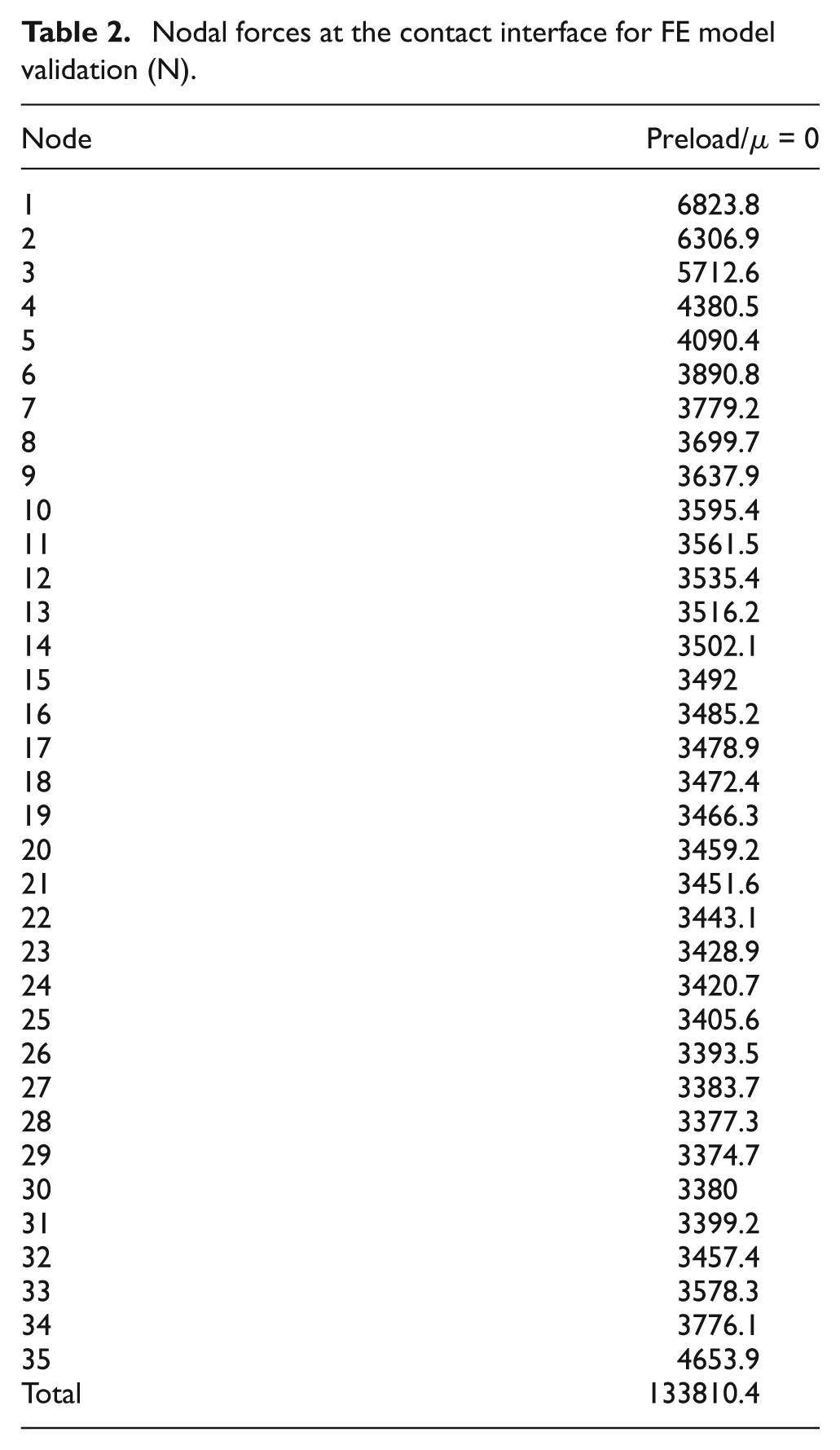
Figure 6 shows FEA results for the tangential stress focusing at the interference contact for tool holder, cutting tool and whole assembly. Comparison of analytical versus FE model validation results are summarized in Table 3, where both analytical and FE model results agree well. As expected, FE model results vary due to nonlinear nature of the problem depending on the contact characteristics, geometry, and so on, which is not the case for analytical calculations.
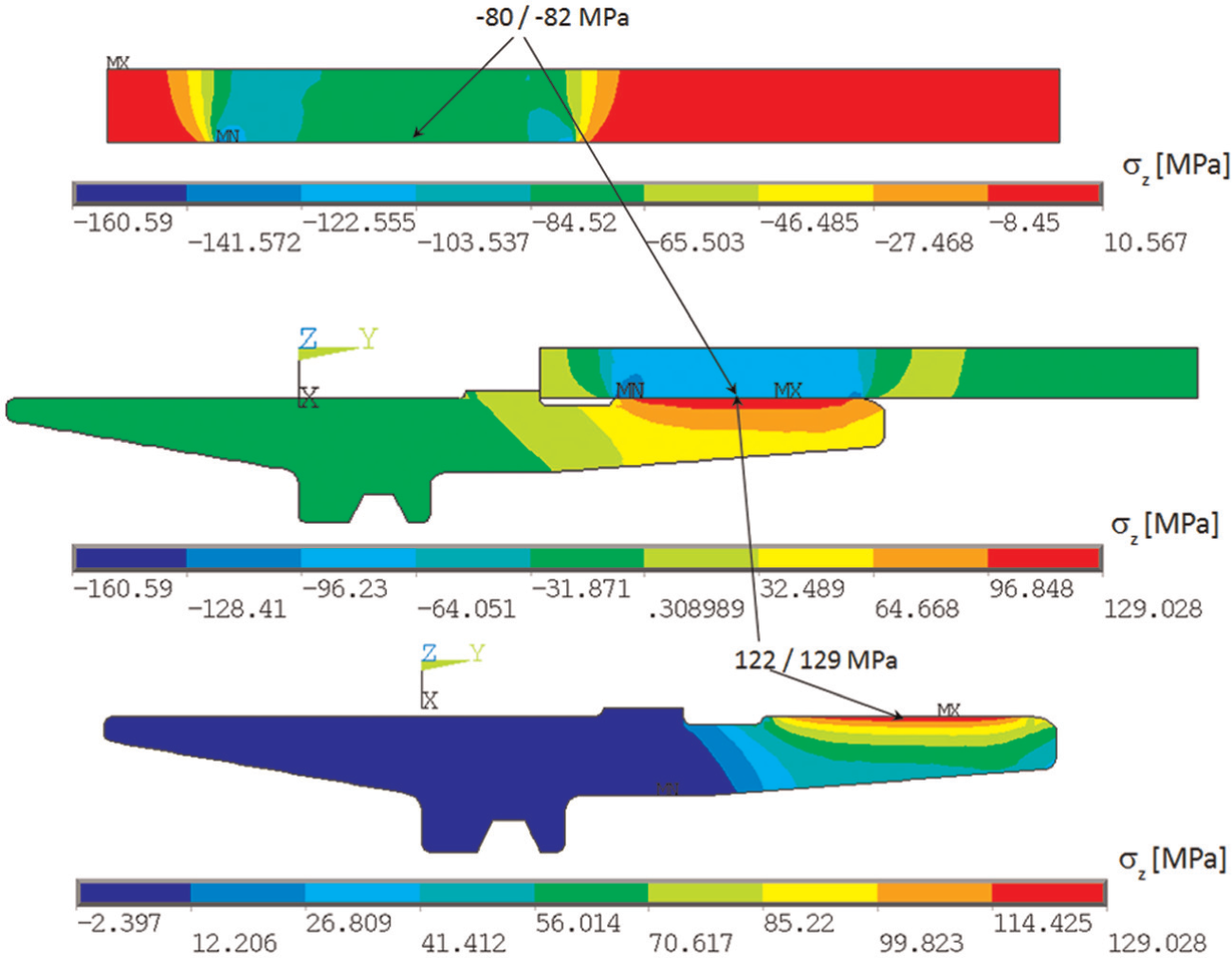
Tangential (hoop) stress distribution for FE model validation runs.
Comparison of analytical versus FE model results (MPa)
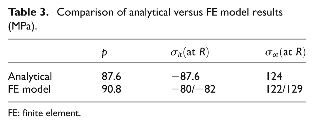
FE: finite element.
Now, we are confident that the proposed FE model simulates the shrink-fit tool holder and tool contact mechanism well. Going back to actual structural analysis, the validated FE model is now exposed to transient temperature distribution at T = 0.1E−05, 7 and 60 s, where transient structural analyses are performed sequentially. Note that at T = 7 s, only tool holder expands since it is the only part exposed to heating. Thermal contact radius expansion on the tool holder due to inductive heating is calculated and plotted in Figure 7.
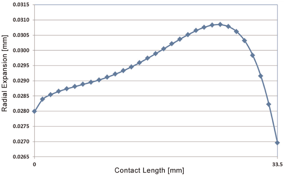
Thermal radial growth of tool holder along contact length at T = 7 s.
In the next step, rapid cooling occurs from T = 7 to 60 s and whole system temperature goes down to room temperature of 20 °C and shrink-fit clamps. Friction is turned on at the contact interface. At the nominal diameter of tool holder/cutting tool pairs, single interference fit (δ) values are considered as given in equation (1), and diametric interference of δ = 14 mm × 0.001 = 0.0014 mm is found. As it can be seen from Figure 7, since δ = 0.0014 mm, the cutting tool shank should easily fit into tool holder hole after such a radial expansion at contact interface.
Post-processed FEA results for shrink-fit radial displacements and equivalent stress distributions are presented in Figures 8 and 9. Careful examination of Figure 8 shows that cutting tool shank deforms in a negative radial direction and tool holder contact surface deforms in a positive direction, thus interference contact pressure is formed. Figure 9 also shows the stress distribution on the tool holder for preload case (i.e. T = 60 s). Maximum equivalent stress occurs around an average of 190 MPa, excluding maximum stress concentration (275 MPa) mainly due to edge effects. Since the yield limit for the shrink-fit holder material is around σY = 520 MPa, overall maximum elastic equivalent stresses at all operating speeds occur well below this stress.
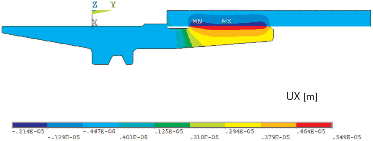
Radial displacements (UX (m)) on shrink-fit tool holder at T = 60 s.
Equivalent stress distribution (σeqv (Pa)) on shrink-fit tool holder at T = 60 s.
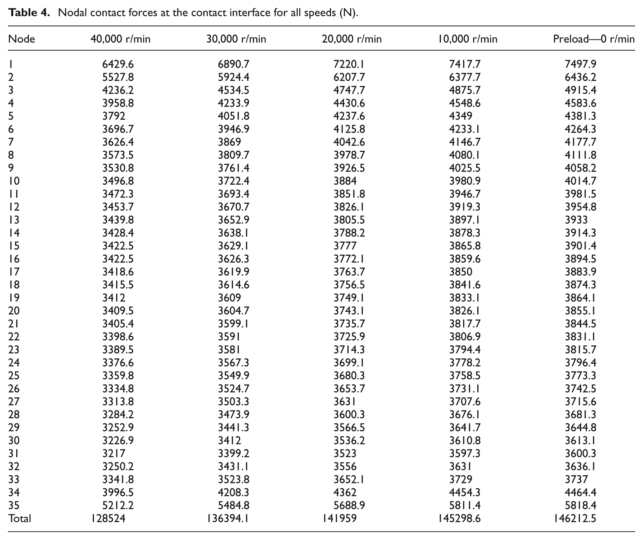
Preload + spin case is considered next, so that stress redistribution (in some sense relaxation) due to centrifugal forces is included/accounted in these FE analyses. Due to spinning effects, the tool holder expands more than that of the cutting tool shank; therefore, at certain spin values, the nonuniform contact force will be lost and cutting torque will not be transmitted, resulting in slip. Nodal radial contact pressure forces along contact interference are obtained after post-processing the FEA results for both preload and 10,000, 20,000, 30,000 and 40,000 r/min preload + spin cases. These values are presented in Table 4, for 35 nodal locations belonging to meshes along 33.5 mm of contact interface length.
Nodal contact forces at the contact interface for all speeds (N).
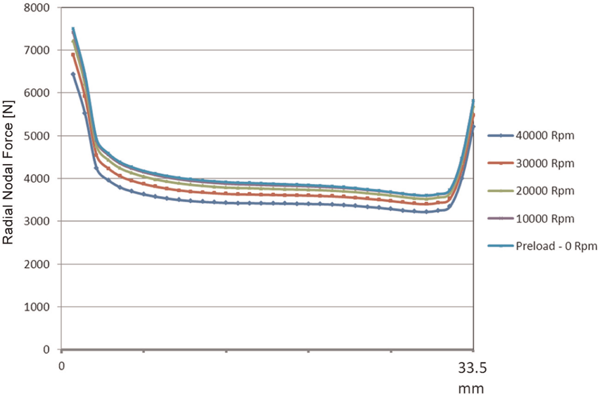
Nodal and total radial contact pressure forces along contact interference are also plotted and presented for both preload and 10,000, 20,000, 30,000 and 40,000 r/min preload + spin cases in Figures 10 and 11.
Contact force distribution along shrink-fit tool holder contact surface.
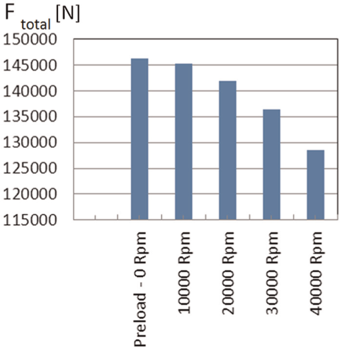
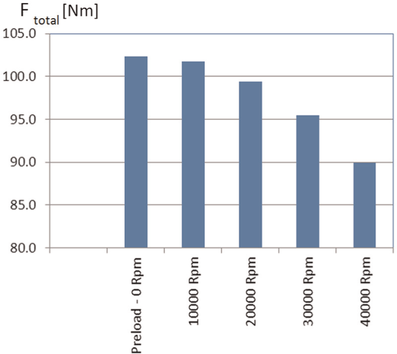
Total contact force at interface for all load cases.
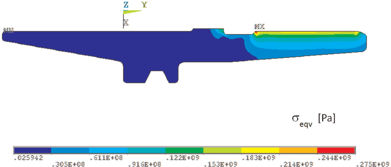
As it is clearly seen from Figure 10, contact forces are higher in the contact beginning and ending locations, and they change nonlinearly (due to contact/geometry), from high to low values toward the tip of the cutting tool holder. One more thing to look at is the total contact force at the interface as presented in Figure 11, where considerable decrease (i.e. from 146.2 to 128.5 kN, around 12% reduction) in magnitude is observed as the cutting tool spins. This can be attributed to centrifugal forces (due to spinning), creating overall stress relaxation. Equivalent stress distributions for all load cases are also presented in Figure 12, clearly exhibiting high stress gradient at shrink-fit regions.
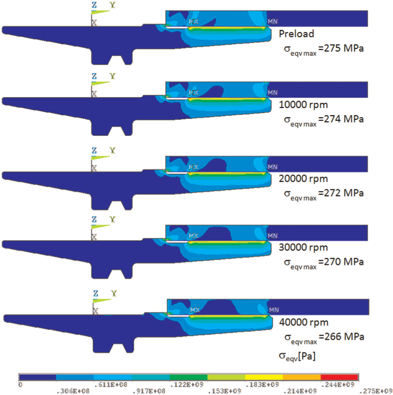
Equivalent stress change for all load cases using fixed contours (0–275 MPa).
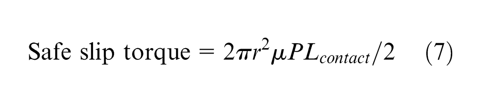
Finally, we can use both Ftotal (total force), which is obtained from structural FE analysis as plotted in Figure 11, and equation (7), where safe slip torque can be calculated by dividing slip torque (nominator) by a factor of safety of 2 as plotted in Figure 13.
Safe slip torque at contact interface for all load cases.
Conclusion
Design of any engineering system is an iterative process which matures with certain number of cycles. This study outlines a complete hands-on design evaluation using FE-based analysis where shrink-fit tool holder and cutting tool geometry are analyzed using both thermal transient and transient structural coupled analyses for a single design cycle of iteration. These analyses serve as automated computer-aided simulation tool, first for the assessment of required nominal interference-fit depth for true cutting conditions and second for the calculation of elastic stress levels at both preload and preload + spin cases. These calculations exhibit highly fluctuating characteristics due to the nonlinear nature of the contact analysis and tool holder geometry. Proposed FEA procedures offer a solid and useful tool (sometimes these outcomes are underestimated by some people who have no insight/idea from practical/industrial application point of views), and require rather good sound procedural application and experience. Using these proposed approaches, any design iteration can be conveniently simulated on computers and their solutions are obtained in a shorter period of time, as this study also contributes in elevating product quality by establishing fast and reliable product design analysis.
Footnotes
Declaration of conflicting interests
The author declares that there is no conflict of interest.
Funding
This research received no specific grant from any funding agency in the public, commercial or not-for-profit sectors.