
Abstract
Electrical discharge milling–based processes are a good alternative for the manufacturing of micro-tools. However, some limitations must be considered both on the fields of process cost and control of surface characteristics. The inverse slab electrical discharge milling (ISEDM) process is an economic alternative to other high-precision high-cost machining processes because a conventional slab electrical discharge milling (SEDM) machine can be used to produce high–aspect ratio cylindrical tools with diameters as low as 200 µm. In this article, the influence of process variables on the surface integrity generated by the ISEDM process is presented. An experimental model aiming at the prediction of both surface finish and thickness of the recast layer as a function of the spark characteristics is developed. The influence of process variables is then analyzed. The model was validated with a high degree of agreement by carrying out experimental tests on submicron sintered high-speed steel micro-pins. Micro-tools with a diameter 335 µm and an aspect ratio as high as 90:1 can be manufactured using this novel technique with a surface finish below Ra 0.7 µm and thickness of recast layer below 3 µm.
Introduction
Manufacturing of micro-pins with a diameter smaller than 1 mm is a field of great interest both in research and in industrial application. There are a wide variety of components of low-diameter cylindrical geometry for various applications. In recent years, there is an active field of research focused on the proposal, definition, and optimization of different manufacturing methods depending on component diameter, aspect ratio, geometry, surface quality, and material. 1 Examples include precision products such as gear shafts, valves, shafts, and channels of micro-fluidic systems, parts for micro-pumps and turbines, mechanical and electrical contact probes, micro-ejector pins in injection molds or micro-tools. The requirements of these products have to contemplate the diameter range between 10 µm and 1 mm, but also maintain good surface integrity in order to increase the life of the micro-components.
Cylindrical structures are fundamental for the manufacturing of micro-tools for micro-machining. Micro-machining is highly dependent upon advances in the development of both ultra-precise machines and micro-tools. Important problems in micro-tool manufacturing technology are availability, unreliable tool life, and early tool failure. As result, there is a large field of study about the use of coatings on cylindrical micro-substrates to achieve tools with more durability.2,3 These cylindrical micro-substrates are manufactured in sintered high-speed steel (HSS) and hard metal (HM), materials that are brittle and difficult to cut. On the contrary, the requirement of low surface roughness is imposed on substrates for micro-tools in order to achieve good adhesion with the coating. These requirements are difficult to be met all at a time, and from this situation arises the growing interest for new optimized production techniques of enhanced performance. Grinding and electrochemical techniques4,5 have been studied but important attention is currently being paid on electrical discharge machining (EDM)-based methods.6–9 The EDM process removes material by a series of discrete electrical discharges that cause localized temperatures high enough to melt or vaporize the metal in the immediate vicinity of the discharge. The only requirement is that both electrode and workpiece materials are electrically conductive. The discharges occur between the tool (electrode) and the workpiece in a dielectric medium under voltage drops over 20 V.
Since material removal is not carried out by the mechanical action of a cutting or abrasive tool, the EDM process can be used independently on the mechanical properties of the workpiece material; for instance, it does not matter how high its hardness is. Therefore, the process has become very popular in the tool-making industry, in which complex geometries with tight tolerances must be generated on difficult-to-machine materials. With the aim of optimizing the process, the study of the influence of process parameters on different materials has been a recurrent issue for many investigators, using most of them techniques based on design of experiments (DoE).10,11 However, the quality of the EDM works is affected by the electrode wear, and as a result, the EDM process needs to use complicated compensation strategies on electrode wear, and different electrodes for a single work (roughing electrode, finishing electrode, etc.).
The fact that the EDM process does not impose mechanical forces on the machined part is critical when considering its successful application for the production of micro-rotational components. This is why different variations of the conventional EDM process aiming at the production of micro-rotational parts can be found in recent literature. In all the cases, the workpiece rotates and there is a relative movement between the part and the tool comprising linear and rotational motion. 12
Due to its characteristics, wire electro discharge grinding (WEDG) has attracted a lot of attention in recent years. Many authors use this configuration because it provides high aspect ratios and great flexibility to produce micro-cylindrical parts with different shapes. As an example, tungsten carbide rods of 100 µm diameter with a rounded tip have been presented by Lin et al. 9 However, the WEDG configuration uses micro-EDM machines, and therefore, it is an expensive method that it can only be afforded by very specialized industries.
A low-cost alternative to the above-mentioned EDM-based processes has been recently presented. 13 The inverse slab electrical discharge milling (ISEDM) process can be carried out in a conventional EDM machine, being thus characterized by its ease of operation and its low operational costs. Figure 1 represents the kinematical configuration of the process. A relative linear movement is imposed between the rotating micro-tool and the block electrode. At every moment, a fresh electrode surface is involved in the process, and therefore there is no need for complex wear compensation techniques. The process is designed in such a way that the reduction in radius achieved in the micro-tool is equal to the maximum possible gap between both elements. In other words, while the gap is smaller than that maximum value, discharges take place leading to the reduction in the diameter of the micro-tool.
Geometrical configuration of the ISEDM process.
Discharges occur between the rotating micro-tool and a fresh new surface of the electrode, that is, a surface that has not been altered by previous discharges. This is critical and it is an important difference with conventional EDM, since the final surface finish of the component is influenced by the finishing of the electrode. Other important differences can be observed, namely,
Sparks remove material from a rotating surface. Therefore, the rotational speed has a non-negligible influence on the material removal mechanism. 14
The volume of material of the micro-tool is very low, so its heat conduction capacity is largely reduced.
The low rigidity of a very high–aspect ratio micro-tool can be the cause of the occurrence of dynamic effects (vibrations) that alter the gap size.
The process does not require using complex wear compensation strategies.
Using this configuration, high–aspect ratio micro-pins with diameter ranging between 0.2 and 0.5mm have been manufactured, 14 For this propose, the use of a multistage strategy involving successive EDM regimens characterized by the discharge energy is recommended.
No matter the configuration chosen, the rotary movement influences process behavior and therefore the achievable results. Studies concerning the influence of peripheral speed on process variables can be found in the scientific literature,15,16 where electrode rotation is studied with respect to metal removal rate, surface roughness, and wear electrode rate; however, the works did not study the recast layer that was formed in the manufactured cavities, a very important factor in EDM processes that affects the surface integrity.
Although it is accepted this process is novel, there is still a lack of scientific understanding about the different effects that result from the relative movement. 12
Due to the thermal nature of the EDM process, the surface integrity of the machined component is affected, which in turn may generate negative effects on service performance. Part of the discharge energy is effectively used to remove workpiece material, which is flushed away by the dielectric fluid. However, a part of the molten material resolidifies again on the electrical discharge machined (EDMed) surface, generating the recast layer, which is referred as “white layer” due to its white color under microscopy after Nital etching. Depending on its application, the quality of an EDM product can be evaluated in terms of its surface integrity, which is characterized by the surface roughness, and by the properties of the recast layer. The importance of reducing the white layer is highlighted by several authors,17–20 who have tried to minimize its thickness using different operating conditions as pulse off-time, intensity, material properties of the tool electrode, dielectric liquid, and so on. Metallurgical transformations in the base material below the recast layer must also be considered, as this effect has huge impacts on mechanical properties of the material such as fatigue strength, hardness corrosion, and wear resistance.17,21 Micro-hardness is another property that affects surface integrity of a product. Some authors 22 have attempt to enhance surface micro-hardness of titanium alloys via modification of electrical parameters as well as using new materials for the tool electrode with different concentrations of dielectric fluid.
From the literature review, it can be concluded that EDM-based processes are a good alternative for the manufacturing of micro-tools. However, some limitations must be considered both on the fields of process cost and control of surface characteristics. Previous publications13,14 have studied the recently presented ISEDM process from the point of view of geometrical accuracy and comparison with static EDM. Following this line of research, in this article, the influence of process variables on the surface integrity generated by the ISEDM process for the manufacturing of high–aspect ratio micro-tools is studied. Section “Process description and experimental set-up” gives a short introduction to the kinematics of the process, the main differences in the surface generation mechanisms, and the experimental set-up for the research work. In section “Experimental model for prediction of thickness of recast layer and surface finish in the ISEDM process,” a model to predict both surface finish and the thickness of the recast layer as a function of the energy characteristics of the EDM regime is presented. Results from the experimental study using scanning electron microscopy (SEM) and roughness measurement show that micro-tools with a diameter 335 µm and an aspect ratio as high as 90:1 can be manufactured using this novel technique with a surface finish below Ra 0.7 µm and thickness of recast layer below 3 µm.
Process description and experimental set-up
Although surface generation in conventional EDM has been a classical topic of research, the above considerations explain that there is no information available in the scientific literature about this process configuration. Therefore, in this article, an experimental study for modeling both surface roughness and thickness of recast layer in the ISEDM process is presented. The study includes the process variables that introduce noticeable differences with conventional EDM.
Following the need for a low-cost application of the ISEDM process, a conventional slab electrical discharge milling (SEDM) machine has been used for the test bench. A prototype has been installed on an ONA Techno H-300 SEDM machine. A block electrode is fixed on the Z-axis of the machine, while the rotating workpiece is mounted on a Hirschmann H80R.MAC.44 rotary indexing table. The workpiece material for the study is submicron sintered HSS Vanadis 23 with a hardness 62 HRc after quenching, commonly used as base material for the manufacture of micro-tools requiring a high wear resistance.
In the context of the ISEDM process, manufacturing of a micro-pin must be carried out using a multistage strategy, involving the use of a roughing regime and a semi-finishing regime followed by a finishing regime, and finally a fine-finishing regime. POCO EDM-1 (fine graphite, recommended for jobs where highly energetic regimens are used, as it provides good material removal rates (MRR)) has been used as electrode material for the roughing and semi-finishing regime. Graphite infiltrated with copper has been selected for the finishing stages because it provides a good compromise between cost, MRR, and part quality achieved. Finally, angstrom-fine-gaphite has been selected for the regime associated to the final surface finish due to its capacity to achieve very low surface roughness. These electrodes were ground to a surface finish of about 0.2 µm Ra.
The above-mentioned multistage strategy requires data about the diameters and aspect ratios achievable with each EDM regime. These data have been obtained from experimental tests and have been collected in Table 1, together with data relating geometrical accuracy of the component and MRR.
Limiting values obtained for workpiece diameter, aspect ratio, geometrical accuracy, and material removal rate (MRR) in the multistage strategy for the ISEDM process.
In Figure 2, a micro-tool of diameter 335 µm and an aspect ratio of 90:1 obtained after the fine-finishing stage is presented.
General view of a micro-tool of diameter 335 µm (up) and an aspect ratio 90:1 (down) SEM image of the tip (×50).
The above data include information about geometrical capabilities and MRR achievable with the process. However, the production of micro-tools introduces a further demand on the process: the requirement for optimum surface integrity of the component, expressed in terms of surface finish, and thickness of recast layer. In the following section, an experimental model for the prediction of both variables in the ISEDM is described.
Experimental model for prediction of thickness of recast layer and surface finish in the ISEDM process
The DoE is a common tool in both industry and research for process modeling and optimization. In this work, a multilevel design with quantitative variables has been selected, in this case, the so-called central composite rotatable design has been chosen.
The successful application of DoE techniques is dependent on an adequate selection of the input variables for the model. This point demands understanding the physical behavior of the process, which in this case is the heat conduction phenomenon through a rotating cylindrical body. Taking this into account, the following variables have been considered in the model:
For a given tool material, the heat conduction capacity is determined by the geometric features of the part, namely, workpiece length (L) and workpiece diameter (D).
The rotation of the micro-tool affects both the heat conduction and the convective action of the fluid. Thus, the rotational speed (ω) of the workpiece has been included in the analysis. The studies on the first and second stages show limited influence of the rotational speed variation on the ISEDM process. Therefore, this variable was eliminated in the following study stages.
In conventional EDM, for given process parameters, surface finish is highly determined by pulse off-time (t0). As explained above, it must be taken into account that due to its low volume, the heat dissipation capacity of the micro-tool is very limited. Therefore, the cooling time between two consecutive discharges (i.e. t0) becomes extremely important.
Of course, the energy content of the discharges is also a critical issue. Its influence has been included by considering four different EDM regimens, so that a different DoE is carried out for each one. An EDM regime is a group of electrical parameters proposed by the manufacturer of the machine in order to achieve a certain surface finish and MRR in conventional EDM operation. Each EDM regime is characterized by its own energy content per discharge, so that regimes can be defined for roughing, semi-finishing, finishing, and fine-finishing operations. The settings are included in tables in the computer numerical control (CNC) of the EDM machine. Besides, for each different regime, graphite manufacturers recommend different graphite qualities. Table 2 shows the main features of each used setting.
Regimes and electrical settings used to include the effect of discharge energy in the model.
Since the number of variables is four, a 16-test Hadamard matrix of resolution V must be built. This approach covers the main factors as well as the interactions between each of the two factors, but it neglects the possible interactions between three or more factors. The result is that the degree of influence of each variable, its curvature, and the degree of interaction between different variables can be evaluated. The concept of interaction refers to the fact that the effect of one factor on the global response of the system depends on the level at which the rest of variables are. The Hadamard matrix results in 30 EDM experiments for the first and second stages, and 20 experiments for the third and fourth stages, where rotational speed is eliminated.
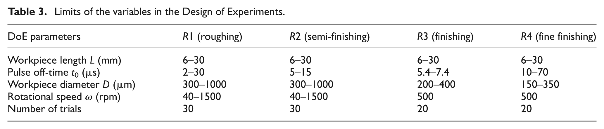
The objective of using the roughing and the semi-finishing regimes is to achieve high removal rates; therefore, discharges are characterized by a relatively high content in thermal energy. R3 is used as a transition to the fine-finishing setting. Bearing this in mind, the limits of the DoE have been set as shown in Table 3.
Limits of the variables in the Design of Experiments.
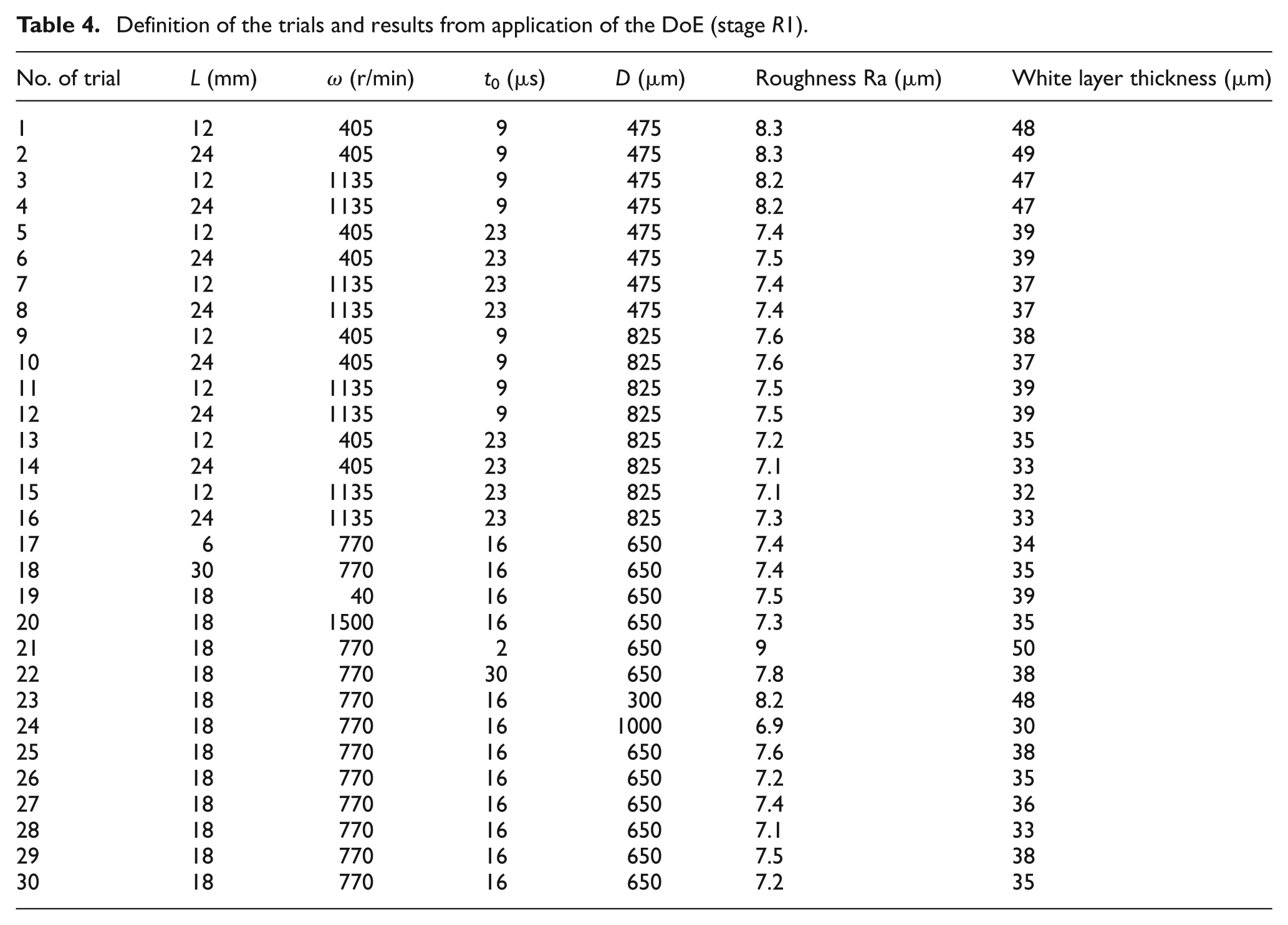
The results of the DoE when applied to R1 are included in Table 4. Similar tables have been generated for regimes R2–R4. From application of the method models that relate the numerical values of the surface finish and the thickness of recast layer to the input variables have been obtained. This technique also yields information about the relative influence of the input variables so that those of negligible influence can be suppressed from the model.
Definition of the trials and results from application of the DoE (stage R1).
Results show a higher surface roughness in the ISEDM process rather than on static parts (conventional EDM) when high-energy regimes (R1 and R2) are applied. The best surface finish obtained using the stage R1 was Ra 7.3 µm while the machine manufacturer is able to obtain a surface finish of about Ra 5 µm with similar electrical settings on non-rotational parts. In fact, the energy density is responsible for this difference. In the case of conventional EDM, regime R1 must be only applied on surfaces larger than 105 mm2. Otherwise, an excessive heat input will result in damaged EDMed surfaces. In the case of ISEDM, that effective area of application is in the range 102 mm2, which explains the difference. Therefore, when low energetic stages were applied, similar surface finish can be obtained in both processes, because the minimum specified area for heat input in conventional EDM is 800 mm2 which, even if still high, is much closer to the surface of the micro-pin. Figure 3 shows the results of the best roughness obtained for each stage on rotary pieces and the values of roughness that the machine can obtain on static parts according to the information provided by the manufacturer.
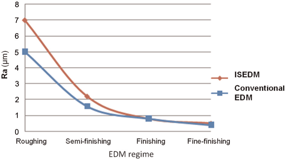
Comparison of surface quality achieved in ISEDM and in conventional (non-rotary EDM) processes as a function of energy content of the discharges (regimens of the multistage strategy from R1 to R4).
From the application of the DoE, it can be concluded that roughness is mainly determined by t0 and D. The rest of input variables show a negligible influence on the process. Equations (1)–(4) express roughness of the each regime/stage as a function of the input variables. The increase in surface roughness was higher when low values of t0 and D were used. Off-time t0 accounts for the time between discharges. In other words, since the effective area of application (governed by D) of the discharges is very small, the progressive heating of this area is governed by off-time. Increasing off-time allows a reduction in the background temperature of the surface of the pin, which in turn reduces the size of the craters produced by the next discharge. Obviously, a similar role can be attributed to D, but in this case related to heat conduction. When taking a look at the differential equation that governs heat conduction, the volume of the solid has a non-negligible effect on the temperature increase. In this case, the effective volume for heat conduction is very small, since the diameter of the micro-pins are well below 1 mm. Any increase in this value moves in the direction of a lower surface temperature, and therefore, a smaller volume of the crater generated by the next discharge
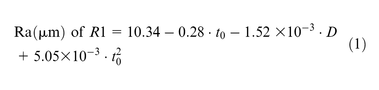
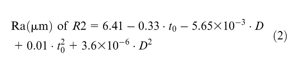
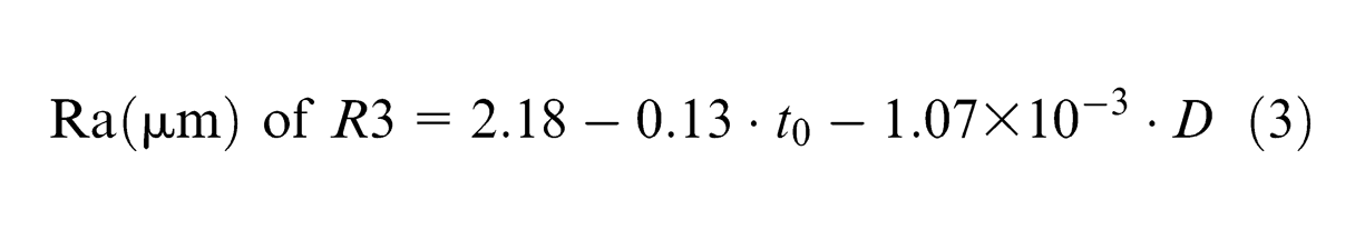
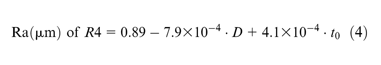
Figure 4 shows SEM images of the surface roughness obtained in the different stages of the ISEDM process. Surfaces are progressively smoother when the energy content of the regime is reduced. Thus, in Figure 4(a), large depositions of molten workpiece material can be observed. Whereas in a conventional EDM operation the pattern of the resulting surface is governed by the superposition of craters produced by the successive discharges, in this case, a different surface topography can be found. An excessive heat density produces too high a surface temperature, producing melting of large quantities of part material that cannot be effectively removed. As a consequence, the molten material redeposits on the micro-pin surface giving rise to the different surface topography encountered in Figure 4(a). The progressive reduction in the energy content of the sparks leads to clear changes in surface topography. The lesser the heat input, the more similar the surface of the micro-pin to that of a conventional EDMed part. Figure 4(d) shows the typical surface finish obtained as a superposition of craters produced by sparks.
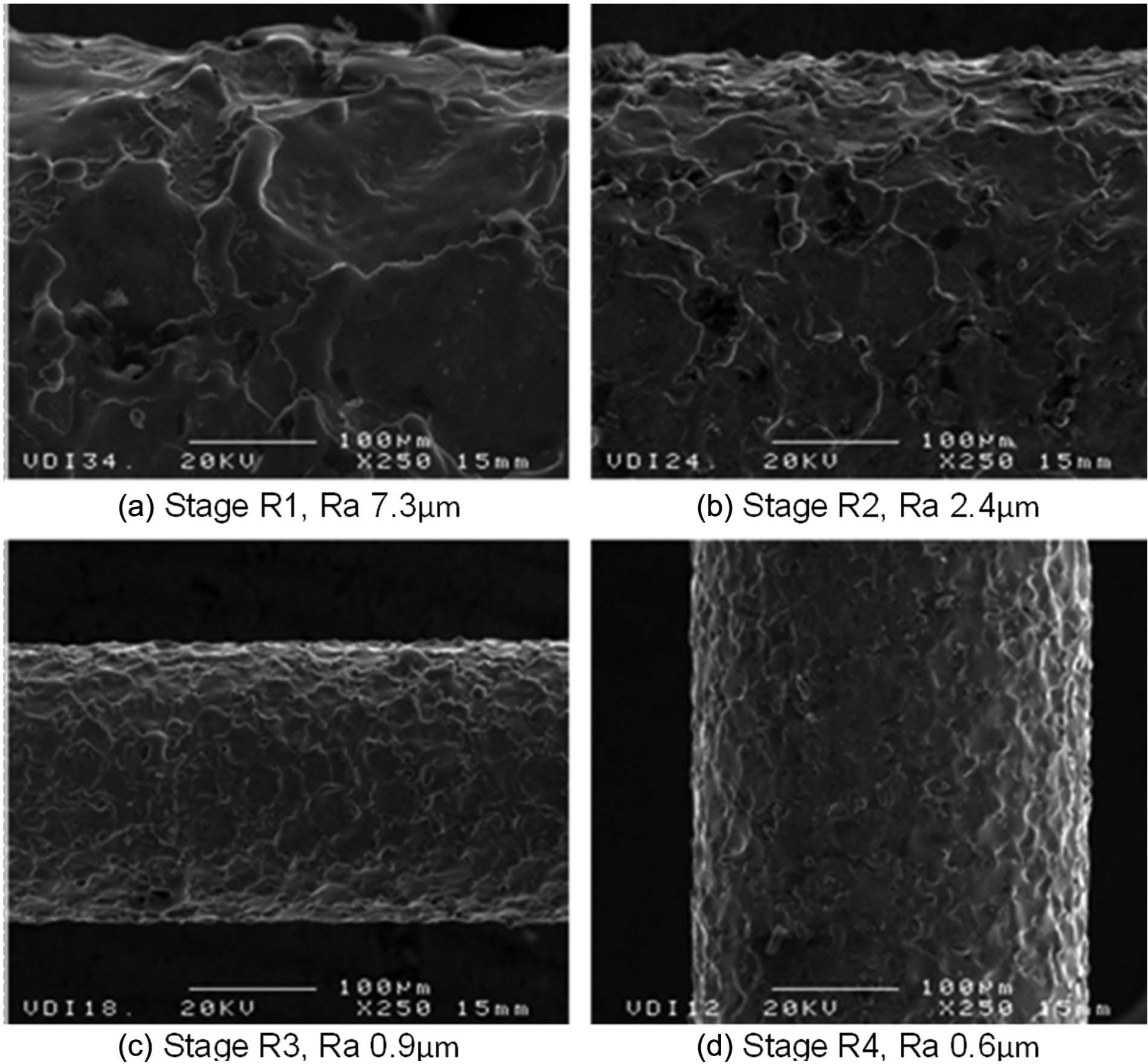
SEM images (
Correlation with the measurements of white layer thickness on SEM confirm the above-commented findings. First, it must be mentioned that the ISEDM process results in higher values of white layer thickness in comparison with those obtained in conventional EDM when high energetic stages (R1 and R2) are applied. Minimum values of 27 and 6 µm can be obtained in R1 and R2, respectively, which are higher than those achieved with similar electrical settings in conventional EDM (11 µm in R1 and 4 µm in R2). Besides, only t0 and D show a significant influence on the white layer measurements, just as happened with roughness values.
Again, the white layer, and any kind of sub-surface material modifications, are produced by an excessive heat input on the EDMed workpiece. The white layer is produced by the molten material and then resolidified on the surface. As explained when analyzing surface roughness, both t0 and D are responsible for excessive heat density on inverse slab electrical discharge milled (ISEDMed) workpieces. As explained in a previous paragraph, the machine manufacturer imposes a minimum discharge area for each EDM regime. Increasing D increases the area of application, and in turn reduces energy density. As far as t0 is concerned, a further effect must be mentioned: if the time between discharges (t0) is too short, the time to carry out an optimum removal of molten micro-pin material is dramatically shortened. As a consequence, a higher part of that material that should have been removed from the cylinder surface gets resolidified, thus giving rise to the hardened layer.
Results of SEM imaging of cross-sectional views of the micro-pins are presented in the following paragraphs. Figure 5 shows the transversal section of ISEDMed micro-tools of diameter 800 and 350 µm (R1). Although the irregular nature of the white layer is evident (resolidified material has been removed from some zones of the micro-pin surface), average values have been used for quantification of the effect. In the case of Figure 5(a), an average value of 33 µm has been measured, this value increasing up to 48 µm in the case of Figure 5(b). The cause must be found in the diameter reduction, which results in a strong reduction of the effective heat interchange surface.
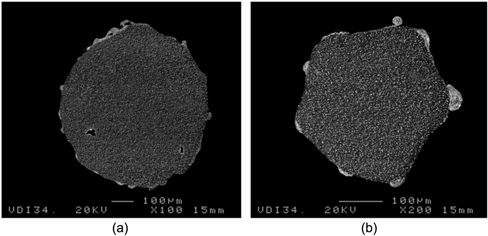
SEM images of micro-tools transversal sections: (a) diameter 0.8 mm and pulse off-time 12.5 µs (magnification ×100) and (b) diameter 0.35 mm and pulse off-time 7.25 µs (magnification ×200). Results for stage R1.
The photographs also reveal another interesting effect: the geometrical error is clearly higher in the case of the low-diameter part. Therefore, by controlling discharge energy and micro-pin diameter, tight tolerances and minimum heat-affected layer can be obtained, as shown in Figure 6(a). In this case, heat evacuation capacity becomes less critical when lower energy regimes are used (discharge current is 0.5 A for R3 and R4) and as a result, the white layer thickness achieved is similar to that expected in conventional EDM in all range of the DoE. Figure 6 shows the transversal section obtained in R4 in the case of a micro-pin of 300 µm where the geometric cylindrical error is low, smaller than 6 µm (Figure 6(a)) and the corresponding white layer, non-uniform and of thickness below 3 µm (Figure 6(b)).
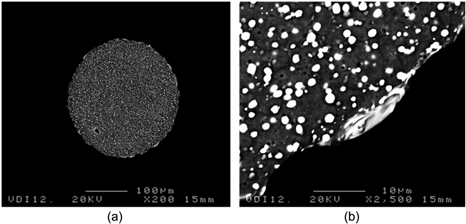
SEM images of micro-tools transversal section of diameter 0.3 mm: (a) general view, geometrical error smaller than 6 µm (×200) and (b) details of the interrupted recast layer, with maximum thickness being 3 µm (×2500).
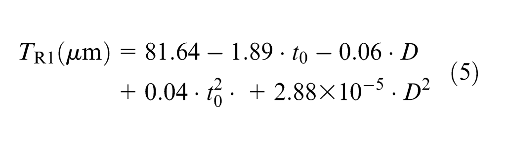
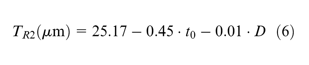
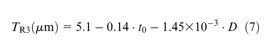
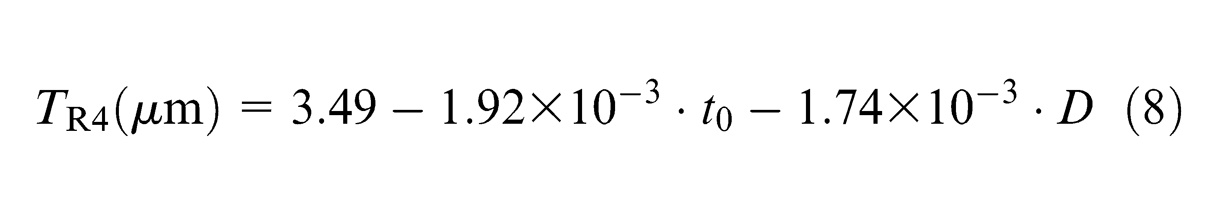
Equations (5)–(8) express white layer thickness for each stage (TR1, TR2, TR3, TR4) as a function of pulse off-time and nominal diameter. These equations show how the lowest white layer thicknesses were obtained with high values of pulse off-time and nominal diameter.
The presented analytical models for surface finish and white layer thickness prediction have been validated against experimental results in the four different EDM regimens studied. Comparison between experimental and predicted results in four different cases has been carried out. Test definition (within the range limits set by the DoE) and results obtained from application of the test are shown in Table 5.
Values obtained in the test for each stage.
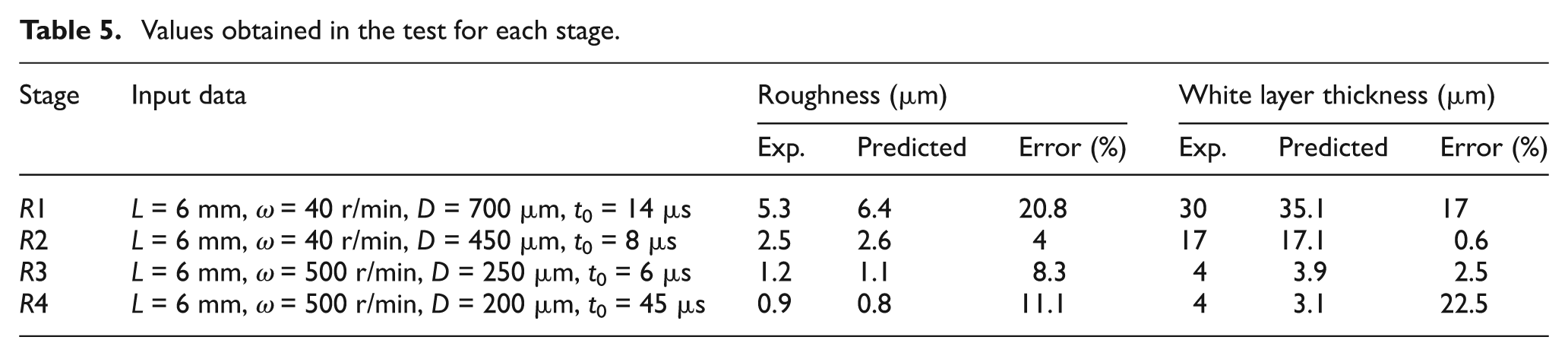
Table 5 collects the data obtained both from the empirical model and from experimental tests for validation. In all the cases, the relative error is below 20%. Taking into account. the uncertainty in the measurements of both values, it can be concluded that the empirical model shows a high degree of agreement with experimental tests. The proposed models can be thus applied to the design of multistage strategies leading to the reduction of surface roughness and the minimization of the thickness of the heat-affected zone in the ISEDM process.
Conclusion
Manufacturing of micro-pins with high–aspect ratio and low diameter involves usually applying expensive machinery and highly skilled operators. The ISEDM process has been proposed as an economical technology that can be implemented at low cost in industrial workshops. Since high–aspect ratio micro-pins are commonly used as base material for micro-tool manufacturing, special attention must be paid to surface modifications produced by the manufacturing process. In this article, the issue of surface integrity and roughness produced by the ISEDM process has been studied using an experimental approach. From the work carried out, the following conclusions can be drawn:
A multistage strategy has been proposed for the manufacturing of micro-pins using the ISEDM process. This strategy involves using EDM regimens characterized by progressively reducing discharge energy. Geometrical errors range from 35 µm in the case of the roughing regime down to 5 µm in the case of the fine-finishing regime. Aspect ratios as high as 90:1 have been obtained at the final stage of the strategy.
Experimental equations based on the technique of DoE have been proposed in order to predict surface finish and thickness of white layer generated by the different stages of the proposed ISEDM strategy. Geometry of the micro-pin (diameter and length), part rotational speed, and pulse off-time have been used as input variables for the experimental model.
For a similar energy content, higher values of both surface finish and thickness of white layer have been observed in the ISEDMed parts when compared with typical values yielded by the EDM process. This effect is clearer in high-energy regimens, and it is attributed to the fact that for the same energy content per discharge, the heat flow is considerably higher in the case of the ISEDM process due to the very reduced discharge surface of the micro-pin.
DoE equations show that pulse off-time and part diameter are the most influencing variables of the model. In the case of the fine-finishing regime, the minimum value of surface finish achieved using the ISEDM process is 0.6 µm, and the minimum thickness of white layer is 3 µm.
The thickness of white layer has also shown a clear correlation with geometrical inaccuracy of the micro-pins. If a high-energy regimen is applied on a micro-pin of small diameter, roundness errors as high as 7.3 µm and thickness of white layer of 27 µm have been observed.
The equations for surface finish and white layer prediction have been validated against experimental results in all the EDM regimes studied. In all the cases, the relative error is below 20%. Taking into account the uncertainty of the measurements (in the range of microns), it can be concluded that the empirical model shows a high degree of agreement with experimental tests.
Footnotes
Declaration of conflicting interests
The authors declare that there is no conflict of interest.
Funding
The authors gratefully acknowledge the funding support they received from the Spanish Ministry of Science and Innovation (MICINN) through the Research Project “Integration of numerical and experimental techniques for the increase of the added-value of precision ground components” (DPI2010-21652-C02-00). Thanks are also due to ONA Electroerosion S.A. for their support to the research.