
Abstract
Currently, the automobile industry is focusing all its attention to creating high-strength, ultra low-weight car bodies. Many techniques can be used to decrease the thickness of a steel plate in a car body but increase the strength. Among these, the hot stamping process makes use of boron steel to produce ultra high-strength components. On the contrary, this process has a low elongation that causes a decrease in collision absorptiveness. Therefore, this study examined the material and weldability of components with high collision absorptiveness using boron steel plates welded at different thicknesses, where the thinner steel sheet can absorb the collision, whereas the thicker steel sheet can endure it. This study was conducted using boron steel coated with either Al–Si or Zn. The results showed that satisfactory tensile strength and elongation could be obtained when both sides of the coating layer were removed by the laser. The hardness in the welded area of Zn-coated boron steel was greater than 450 Hv, even when the specimen was welded without laser ablation of the coating layer, but the coating layer peeled off when heated for 5 min at 950 °C.
Introduction
Because automobiles directly affect the safety of human beings, a major focus has been on developing car bodies with high stiffness. A car body needs to be highly stiff and lightweight because the carbon dioxide exhaust decreases with decreasing car body weight. As global environmental problems have become a major concern, the automobile industry has become increasingly interested in regulating greenhouse gas exhaust and producing cars that are lighter in weight to achieve greater gas mileage. In addition, cars need to have high collision absorptiveness for the safety of passengers during collisions. Achieving all three is quite a difficult task.
Active research aimed at solving such problems is currently focused on the hot stamping process.1–5 Research on martensite formation according to temperature, 6 effects of the forming parameters in a hot process 7 and effects of spring back and residuals on the product 8 have been reported. Although hot stamped products have high stiffness, they are used restrictively in components requiring collision absorption because of their low elongation. Hence, the tailor-welded blank (TWB) technique is used for boron steel in the hot stamping of bonding two steel plates with different thicknesses, where the thicker steel plate can act as a support frame while the thinner steel plate can absorb the collision. Many studies have examined the general bonding of different types of steel. Anand et al. 9 evaluated the mechanical properties of interstitial free (IF) steel with different thicknesses after welding and Padmanabhan et al. 10 evaluated the formability of a bonded material of aluminum and steel. Kinsey et al. 11 conducted a comparative study through formability experimentation and interpretation of a car body door using TWB. 11
On the contrary, there has been insufficient research on TWB boron steel.12–15 Boron steel suffers reduced mechanical properties in the welded region due to the inflow of the Al–Si-coating layer during welding. Therefore, boron steel can only be welded after removing the coating layer. This study evaluated the mechanical properties of welded boron steel. The welding procedure was carried out after ablating the Al–Si-coating layer. Ablation was carried out under a range of conditions. The Erichsen test was used to simulate the hot stamping process. The processing parameters, such as tool temperature and dome height, were varied to achieve the optimal conditions that can lead to the appropriate mechanical properties.
Removal of Al–Si-coating layer and welding of boron steel
Characteristics of boron steel (22MnB5)
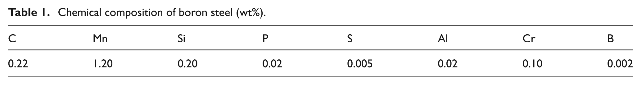
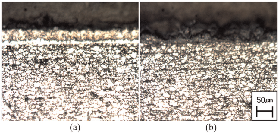
For boron steel, B, Mn, and Cr have been added to achieve excellent hardenability (Table 1). Table 2 lists the mechanical properties before and after the hot stamping of boron steel. Figure 1 shows the microstructures of a boron steel sheet before and after hot stamping. Although pearlite structures were present in the ferrite base before hot stamping, they transformed to martensite after hot stamping.
Chemical composition of boron steel (wt%).
Mechanical properties of boron steel.
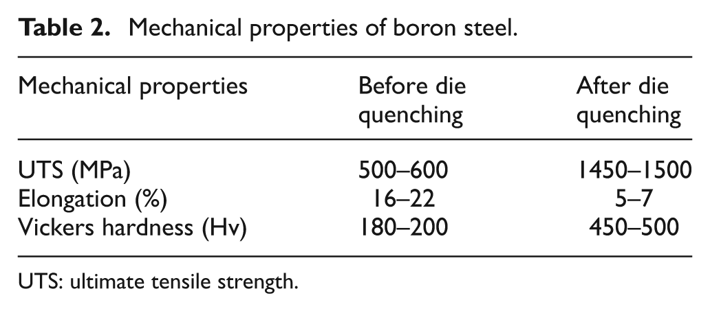
UTS: ultimate tensile strength.
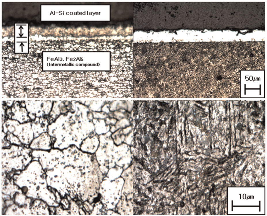
Microstructures before and after die quenching.
Boron steel is plated with a 25–45-µm thick Al–Si-coating layer on both sides of a steel plate to prevent oxidation. Higher hardness is achieved through the presence of intermetallic compounds, such as FeAl3 and Fe2Al5 with a thickness of 5–7 µm between the coating layer and base metal layer. In addition, the melting point of the coating layer is 600 °C–700 °C, but it is 1100 °C for the intermetallic compound layer. Boron steel encounters reduced mechanical properties due to inflow of the Al–Si-coating layer during butt welding.
Ablation of sheets
During ablation by attaching the head that controls the distance between the laser beam and steel sheet, its slow speed can result in incomplete removal of the coating layer and the formation of a molten intermetallic material. Furthermore, when the welding speed increases, the problems of insufficient removal of the coating layer can also occur. Therefore, laser ablation of the Al–Si-coating layer with a 25∼45µm thickness was made possible by attaching a scanner that concentrated light with a lens instead of a head.
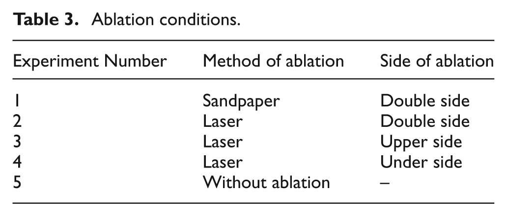
Figure 2 shows a photograph of the top of steel sheet after removing the coating layer through laser ablation, 3 mm from the side (Figure 2(b)). For Experiment Number 1, the coating layers were removed from both sides with sandpaper, but not completely. For Experiment Number 2, the coating layers on both sides were removed with a laser. For Experiment Numbers 3 and 4, the coating layer was removed from the upper and bottom sides with a laser, respectively. Experiment Number 5 was a non-ablation sample. Figure 3 shows the microstructures in the thickness direction after the specimen had been polished and etched before and after laser ablation. Figure 3(b) shows the surface after removing the coating layer.
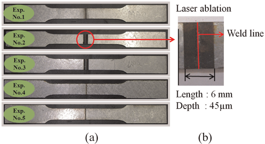
Example specimen of laser ablation and welding: (a) specimen of tensile test and (b) enlarged photo of ablation region.
Before and after laser ablation of the Al–Si-coating layer of boron steel: (a) before laser ablation and (b) after laser ablation.
Table 3 lists the variables for ablation before welding. In Experiment Number 1, the coating layers on both sides of the boron steel sheet were removed manually with sandpaper. In Experiment Number 2, both sides of the coating layer were removed, whereas in Experiment Number 3, only the top coating layer was removed after which it was welded. In Experiment Number 4, only the bottom coating layer was removed, followed by welding. Experiment Number 5 shows the condition in which no coating layers were removed and welded immediately. If there were no differences in the mechanical properties between the samples with the coating layer removed from only one side and samples with coating layer removed from both sides, the prior condition was considered to be suitable due to the potential cost-savings in the process.
Ablation conditions.
Laser welding
A 1.6 mm boron steel (22MnB5) sheet was butt welded after laser ablation. The optimal welding condition must show a narrow weld line and complete back beads due to full penetration after welding. If the speed is too slow, the area of the fusion zone and back bead would become wider due to the high heat input. On the contrary, if the output is high and the speed is too fast, there would be no back bead because of the low heat input, which would cause a decrease in the mechanical properties.
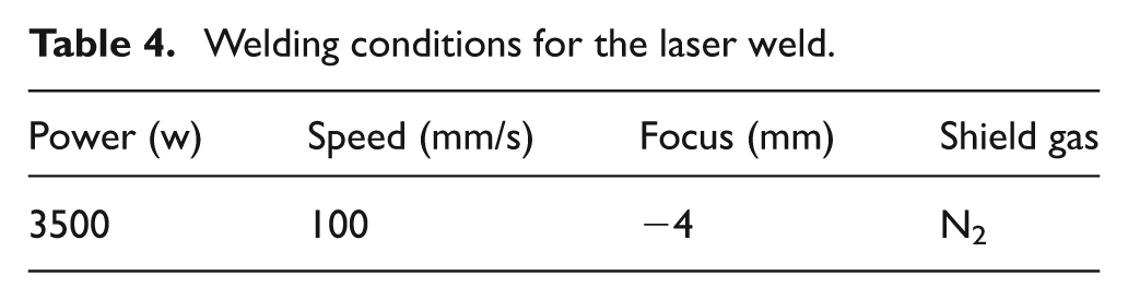
Figure 4 shows a cross-sectional view of the welding zone according to the ablation conditions. A bond area that showed weaker mechanical properties after welding was produced in the heat-affected zone (HAZ) between the base metal and welded area, which became a cause of brittleness. On the contrary, the size of the HAZ area decreased when the welding conditions became optimal. Table 4 lists the welding conditions. Figure 5 shows the laser equipment and tensile test specimen. The tensile test was performed in MTS with a tension speed of 2 mm/min, and the specimen size was standardized to an ASTM E 8 subsized specimen. To reduce the two misalignments of the steel sheet after welding, the burr after shearing was removed, fixed on the tool, and laser welded.
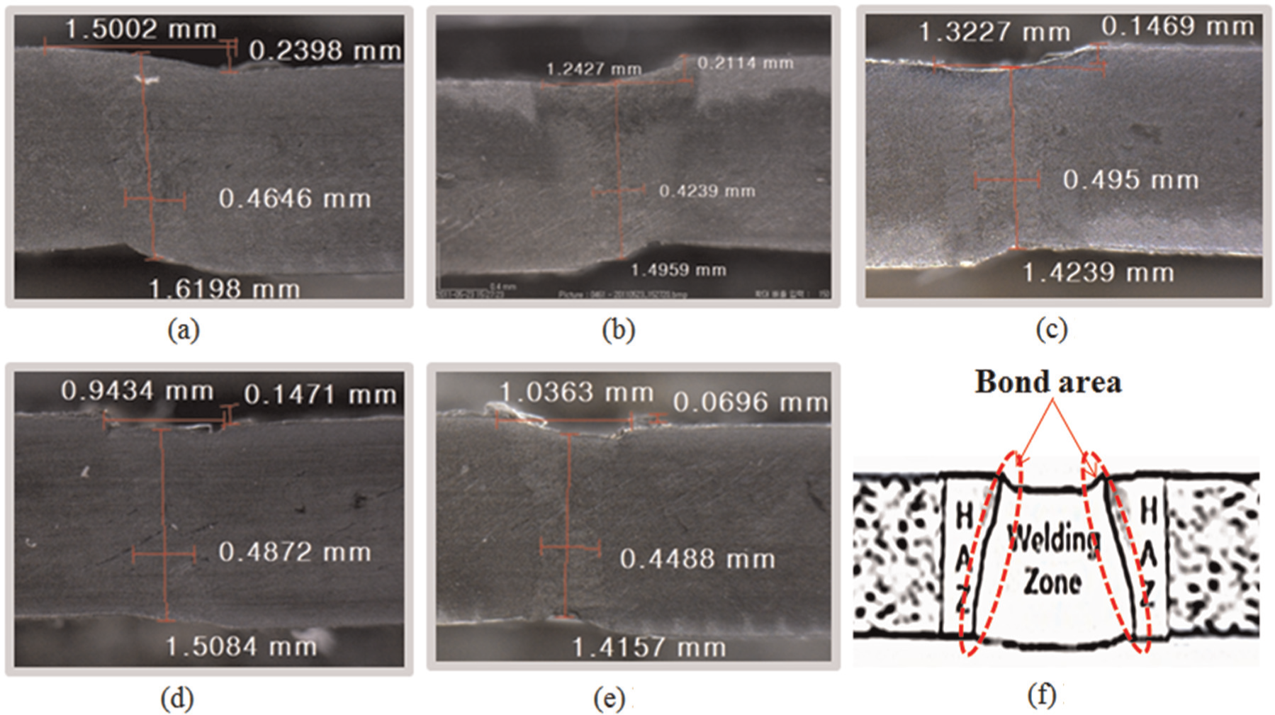
Cross-section view of the welding zone according to the ablation conditions: (a) Experiment Number 1, (b) Experiment Number 2, (c) Experiment Number 3, (d) Experiment Number 4, (e) Experiment Number 5, and (f) bond area.
Welding conditions for the laser weld.
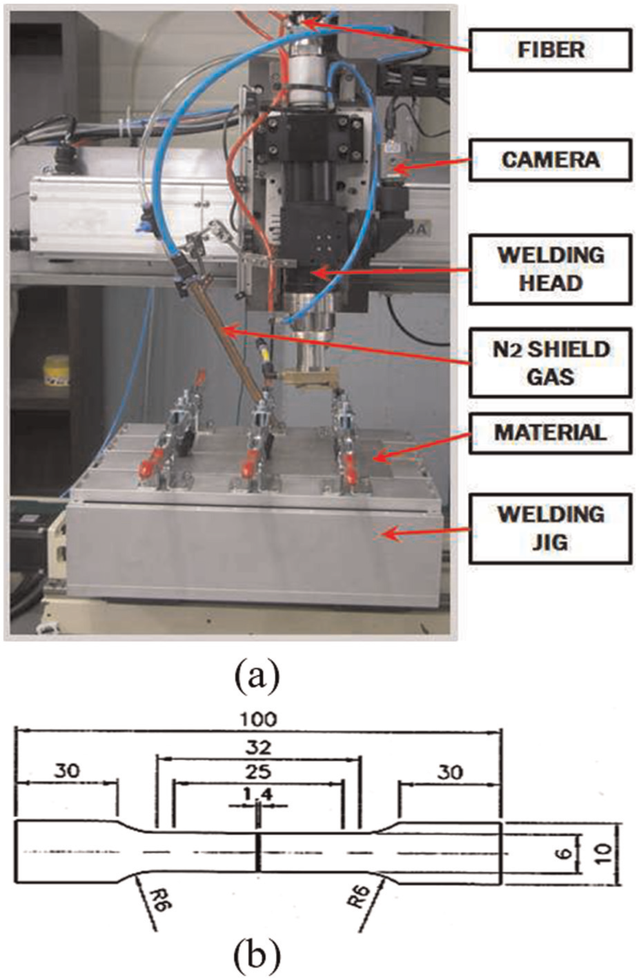
Laser equipment and dimension of the tensile specimen: (a) laser equipment and (b) dimension of tensile specimen.
Evaluation of the mechanical properties
Tensile test
Boron steel, which had been welded after ablation, was machined according to the ASTM E 8M (subsize specimen) for six specimens, where the tensile test was conducted for three specimens prior to quenching and three specimens after quenching. Figure 6 shows the median value after ignoring the highest and lowest values. Figure 6(a) and (b) shows the tensile value before and after quenching, respectively. The tensile properties of the base metal (Experiment Number 6) were added for comparison.
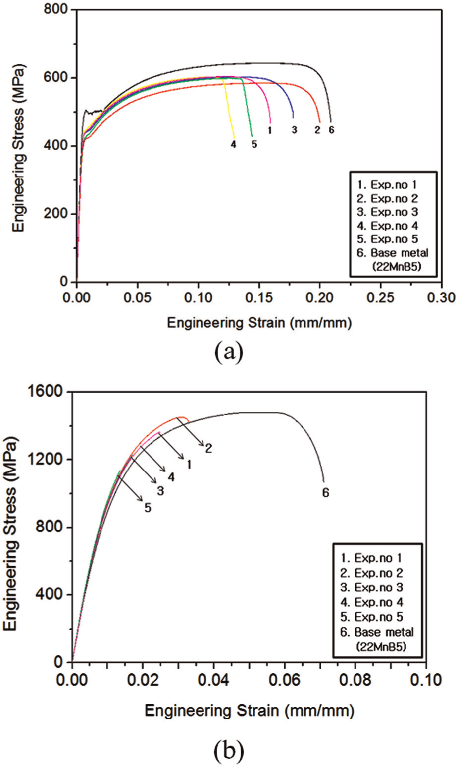
Tensile strength of the specimen after die quenching: (a) before die quenching and (b) after die quenching.
Experiment Number 2, in which the specimen underwent laser ablation on both sides, showed the highest elongation of the ablated specimens; the tensile strength and elongation were 585 MPa and 20%, respectively. The Experiment Number 3 condition with laser ablation applied only to the top of the specimen produced a tensile strength and elongation of 603 MPa and 18%, respectively. The specimen from Experiment Number 1, which had the coating layer removed manually with sandpaper, had a tensile strength and elongation of 604 MPa and 16%, respectively. The tensile strength of the specimens from Experiment Number 4, which had only the bottom side laser ablated, and Experiment Number 5, in which no laser ablation had been applied, were 603 and 599 MPa, respectively; the corresponding elongation was 14% and 16%.
In this study, boron steel was coated with an Al–Si-coating layer. For Experiment Number 1, the coating layers on both sides were removed with sandpaper, but not completely. For Experiment Numbers 3 and 4, the coating layer was removed from only one side by a laser. Experiment Number 5 was the non-ablated sample. If the coating layer is not removed completely, compounds, such as FeAl3 and Fe2Al5, can form from the remaining coating layer during welding. Figure 7 shows the energy dispersive spectroscopy (EDS) results of the specimens according to the ablation method. The negative value means that Al and Si were not found. As shown in Figure 7, Al and Si were found in the welding zone except for Experiment Number 2 (both side laser-ablated specimen). EDS confirmed that when the coating layer was not removed completely (Experiment Numbers 3–5), Al and Si melted and intermetallic compounds formed during the welding process. The FeAl3 and Fe2Al5 compounds were brittle and the ductility in the welding zone decreased. The formation of these intermetallic compounds under different ablation conditions can explain the differences in the elongation values.
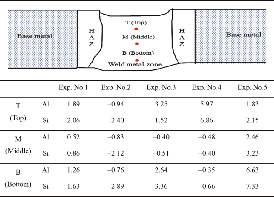
Al and Si wt% result of EDS analysis according to the ablation method.
For the conditions after quenching in the order of descending elongation, the specimens from Experiment Number 2 showed a tensile strength and elongation of 1451 MPa and 3%, respectively. Although this is a low elongation value compared to the base metal, the tensile strength satisfied the 1450 MPa level, which is the minimum requirement for use as a hot stamping component in the automobile industry. All other conditions of the specimens had very low tensile strength and elongation.
Moreover, the fracture locations show that fractures occurred at the bond of the HAZ. Although both the weld zone (WZ) and base metal turn into a martensite structure, the bond area (Figure 4(f)) of the HAZ is a local area with poor hardness and strength between the base metal and fusion zone during welding.
A comparison of the tensile strength before and after quenching showed that the condition of Experiment Number 2 was better than that of Experiment Number 5, which had been welded without removing the coating layer and had poorer mechanical properties, confirming the need for removing both sides of the coating layers.
Measurement of the hardness and microstructure
Before measuring the hardness, a ∼2 cm specimen was cut and mounted using a polycoat and hardener after being polished to make the surface even, and the Vickers hardness test was used to measure the hardness. The load was set to 1000 g and the measurements were taken at 0.25 mm (250 µm) intervals. Representatively, Experiment Numbers 2 and 5 for the hardness values before and after quenching were used for comparison.
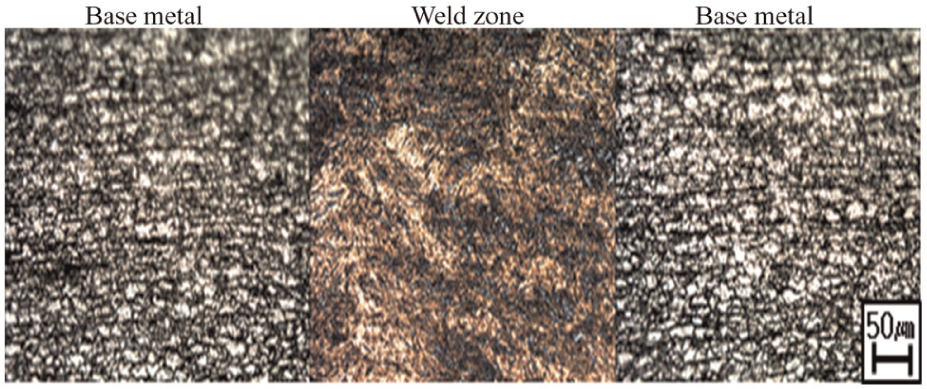
Figure 8 shows the microstructure before die quenching of Experiment Numbers 1–5. A ferrite microstructure was observed in the base material. A martensitic microstructure was observed in the WZ. During laser welding, nitrogen gas causes rapid cooling, which can result in the formation of a martensitic microstructure. As shown in Figure 9, all specimens showed similar tendencies before quenching. A hardness of 450–550 Hv, which is the Vickers hardness of martensite, was obtained in the WZ, whereas the measurement for the base metal was 180–200 Hv.
Microstructures before die quenching of Experiment Numbers 1–5.
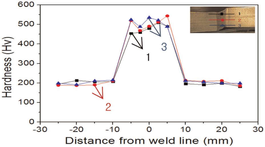
Distribution of the Vickers hardness before die quenching of Experiment Numbers 1–5.
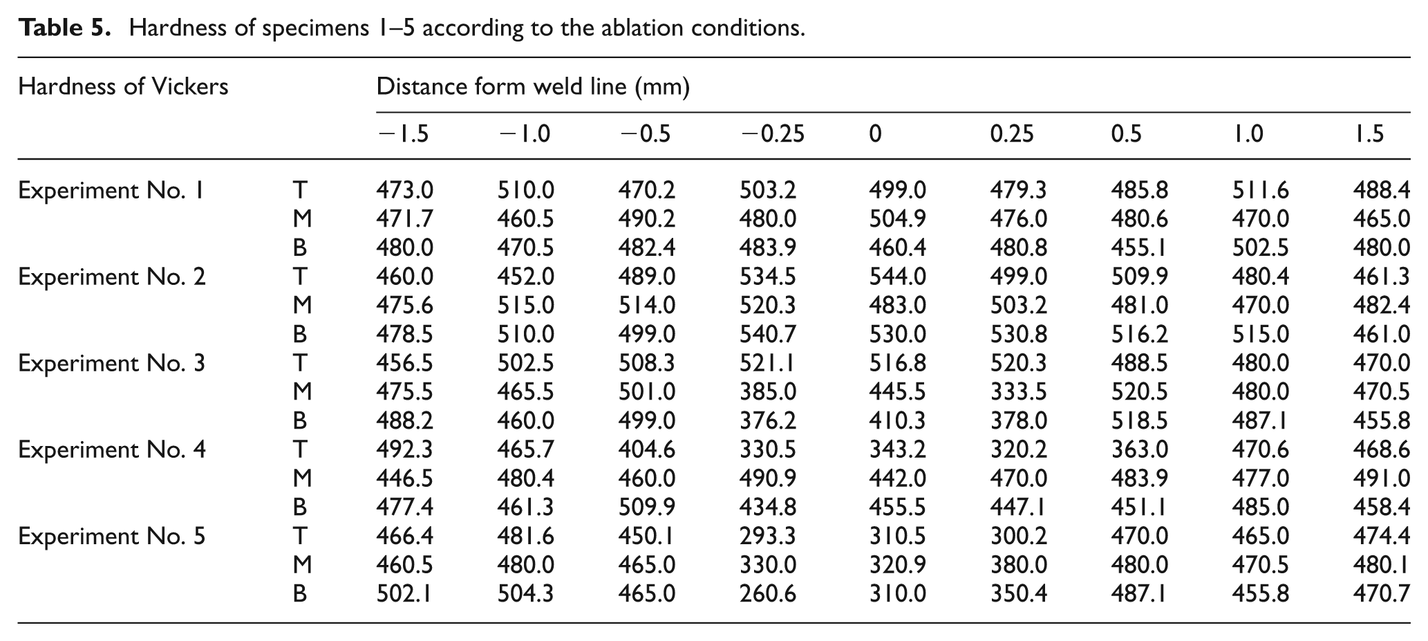
However, a different distribution was observed in the WZ of the specimen after quenching, as shown in Figure 10. The specimen for Experiment Number 2 had both sides laser ablated and achieved an even distribution but the hardness was slightly higher in the WZ than the base metal area. Moreover, the hardness in the WZ decreased to 250–300 Hv for Experiment Number 5 (Figure 10(b)). Table 5 lists the hardness of Experiment Numbers 1–5. Figure 11 shows the microstructure of after die quenching of Experiment Numbers 1–5. Although microstructural photos in Figure 11(a) and (b) show a full transformation to martensite, Figure 11(c)–(e) show both the ferrite and martensite co-existing. A comparison of the tensile strength and hardness showed that boron steel needs to undergo laser ablation for both sides prior to welding.
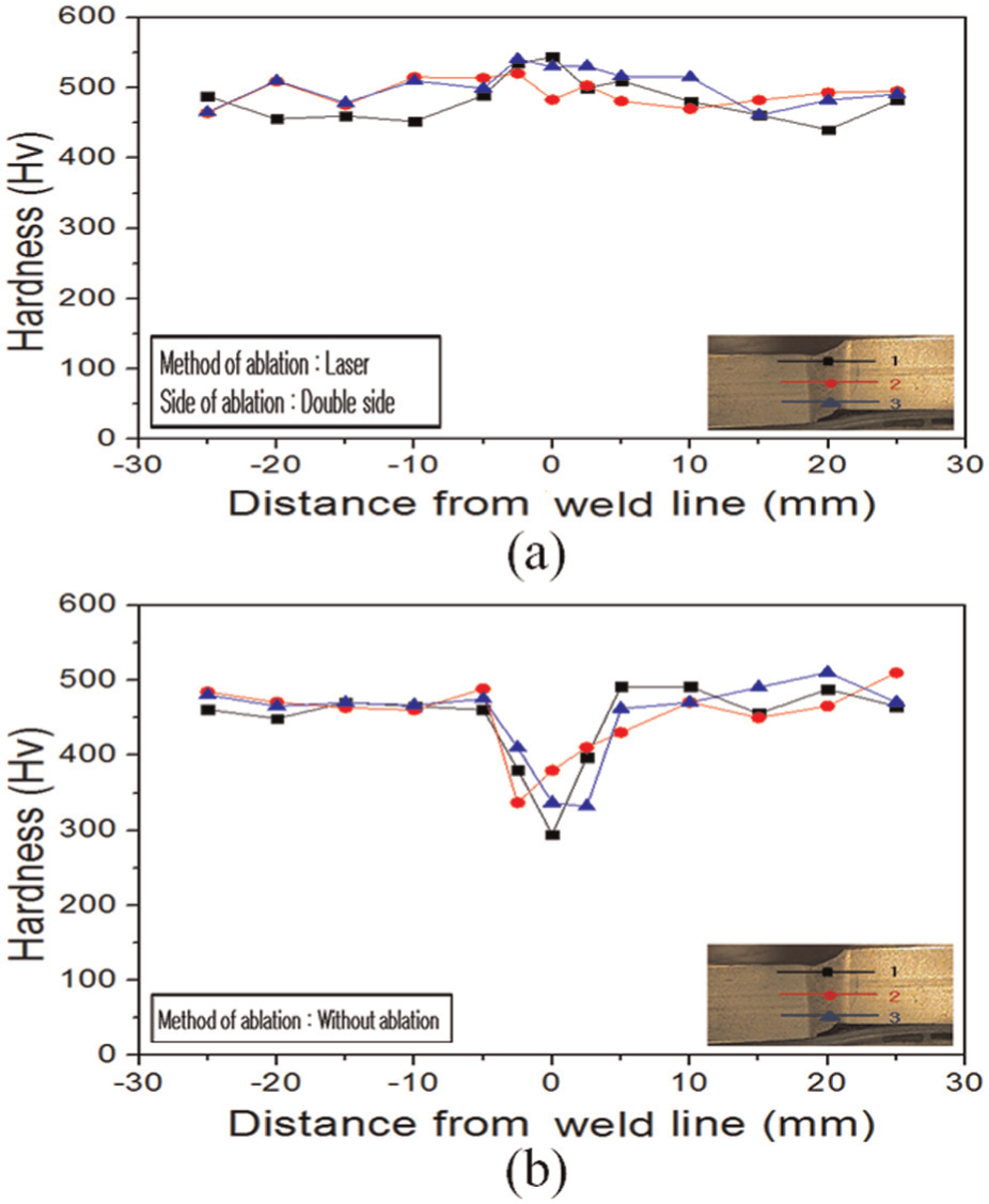
Distribution of Vickers hardness after die quenching of Experiment Numbers 2 and 5: (a) after die quenching of Experiment Number 2 and (b) after die quenching of Experiment Number 5.
Hardness of specimens 1–5 according to the ablation conditions.
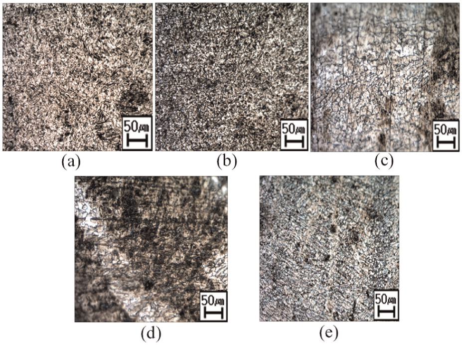
Microstructure of after die quenching of Experiment Number 1–5: (a) Experiment Number 1, (b) Experiment Number 2, (c) Experiment Number 3, (d) Experiment Number 4, and (e) Experiment Number 5.
Evaluation of the welding area properties according to the heat input in laser-welded blank
Measurement of the hardness in the welded area
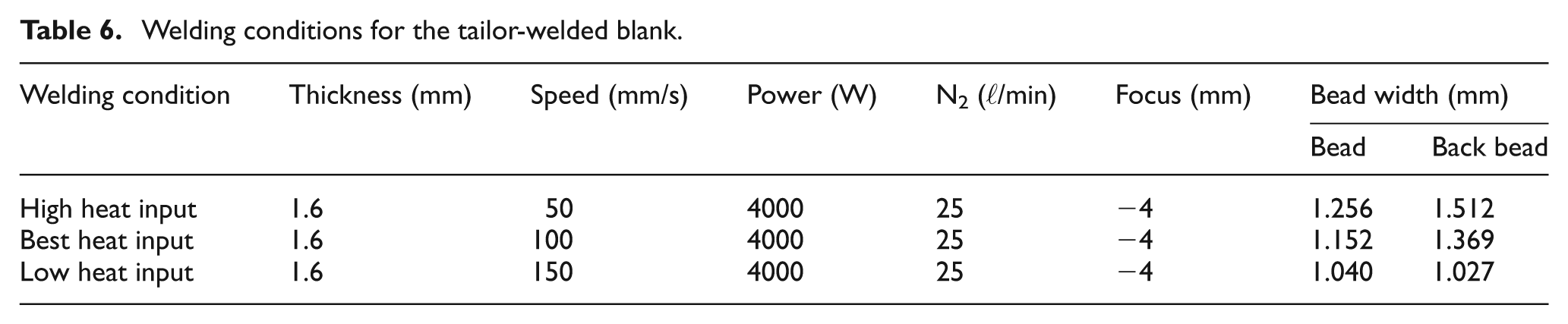
The experiments conducted above showed that the specimens with both sides laser ablated had the best mechanical properties. Therefore, the tests were conducted to obtain the optimal welding conditions to create the optimal laser-welded blank (LWB) boron steel under this condition. In Figure 12, the hardness of the welded area was measured according to the welding heat input. Table 6 lists the welding conditions of the specimen. The variables for heat input were selected to be variables of the welding speed. Under each condition, the lengths of the beads were measured. The size of the beads differed according to the heat input. Figure 12(a) shows the hardness distribution of every specimen before quenching. The width of the welded area increased with increasing heat input. In addition, in Figure 12(b), which shows the results after quenching, a high heat input had a conspicuously larger HAZ, which decreased temporarily, compared to the other conditions. This suggests that as it had been over-welded, and the welded area and HAZ increased in size. Through the temporary decrease in hardness, the location and strength of the fracture can be estimated when evaluating the tensile strength.
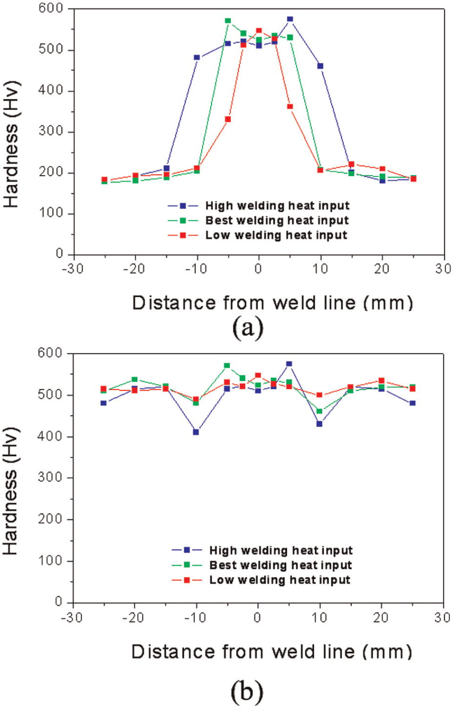
Vickers hardness of the welding surface before and after die quenching according to the welding conditions: (a) before die quenching and (b) after die quenching.
Welding conditions for the tailor-welded blank.
The tensile strength and elongation were measured to determine which condition had the most appropriate strength under the hot stamping conditions after measuring the hardness of the welded boron steel specimens.
Tensile test
Figure 13 shows the tensile strength and elongation before and after quenching according to the welding conditions. In the case of the specimens with a low heat input, the tensile strength and elongation were 1350 MPa and 3%, respectively, which did not reach the tensile strength and elongation results after quenching the boron steel base metal. In the case of a high heat input, the measured values were 1420 MPa and 3%, respectively; under the optimal conditions, tensile strength and elongation was 1470 MPa and 4.5%, respectively. Therefore, these values were selected as the best condition that satisfies the required tensile strength and minimum elongation (5%) of base metal.
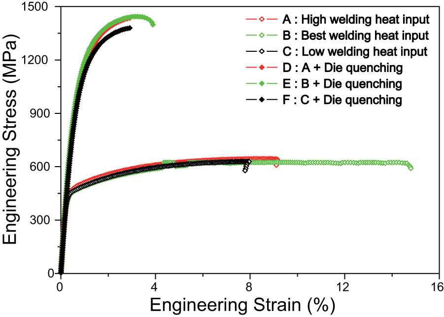
Stress–strain curve according to the welding conditions.
All tensile strengths before quenching were 600 MPa, which is similar to that of the base metal, whereas for elongation, the low heat input and high heat input had measurements of 8%–9%, which is half the value of the base metal. On the contrary, the elongation of the best heat input condition was almost 16%, which satisfies the minimum value of elongation for the base metal. In other words, the WZ and HAZ affect the mechanical strength.
The formability was evaluated by measuring the form depth and punch force through the room temperature and hot deep drawing tests by fabricating specimen under the optimized laser ablation and welding conditions, which had been confirmed through experiments depending on the laser ablation variables and hardness and tensile tests.
Evaluation of formability through deep drawing experiment
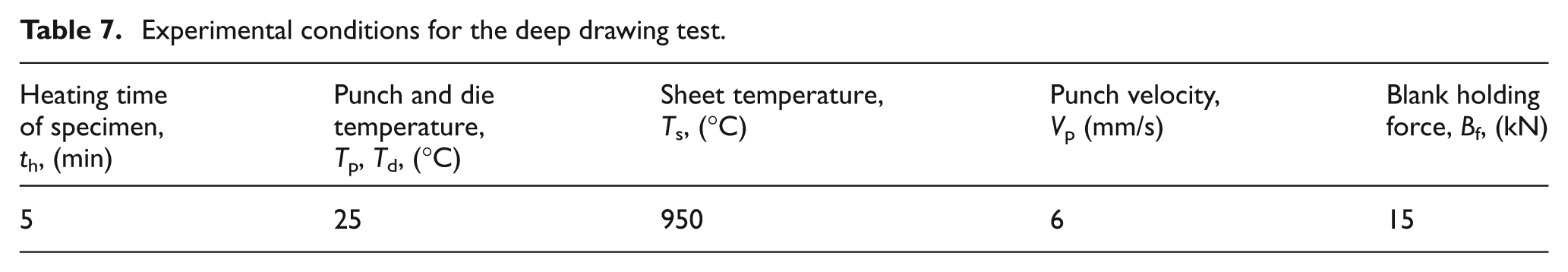
The formability was evaluated by deep drawing experiments under room temperature and hot conditions by fabricating the specimens under the ideal laser ablation and welding conditions. Tables 7 and 8 list the test conditions and conditions for the test apparatus.
Experimental conditions for the deep drawing test.
Dimensions of the tools for the deep drawing test (mm).
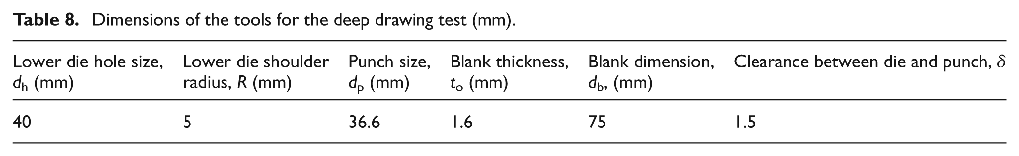
Figure 14 shows the test results. Figure 14(a) presents the results of room temperature forming according to the heat input. The punch force and form depth increased with increasing heat input from low to high. Figure 14(b) shows the results for hot deep drawing experiment that simulated the hot stamping process. When looking at the form depth, fracture occurred at 5 mm for a low heat input, whereas it was 10 mm for a high heat input. Fracture occurred at 11 mm for the ideal heat input.
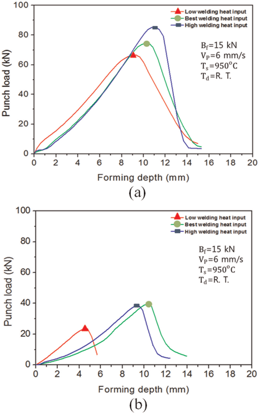
Correlation between the punch load and forming depth according to cold and hot deep drawing: (a) cold deep drawing and (b) hot deep drawing.
In other words, as estimated in the hardness and tensile tests, the values selected under the ideal conditions gave the best results for the formability. A high heat input has disadvantages in having a wide HAZ, whereas a low heat input results in decreased mechanical strength due to the incomplete formation of back beads. In addition, cold forming showed better formability than cold and hot forming. However, the punch force was reduced by more than 50%.
Evaluation of the mechanical properties and coated later during the hot forming of LWB boron steel coated with Zn
Hardness distribution
As shown in the experiments, Al–Si-coated boron steel plates show lower hardness in the welded area, causing poor mechanical properties after being welded followed by a hot stamping process. Therefore, the coating layer must be removed by adding a laser ablation process. On the other hand, for boron steel plates with a Zn coating, the hardness of both the welded area and base metal became greater than 450 Hv when the coating layer had not been removed and the hot stamping process was applied after welding. In other words, Zn-coated boron steel plates can produce a LWB even without laser ablation.
As shown in Figure 10(a), the hardness of the welded area in boron steel with an Al–Si-coating layer laser ablated before and after quenching was greater than 500 Hv. On the contrary, the hardness before and after quenching of the Zn-coated boron steel plate that had been welded without laser ablation had a low tendency of approximately 450 Hv (Figure 15(a) and (b)). Furthermore, a simple comparison of the specimens after quenching showed that the welded area for the Zn-coated boron steel plate had a lower hardness than that of the base metal.
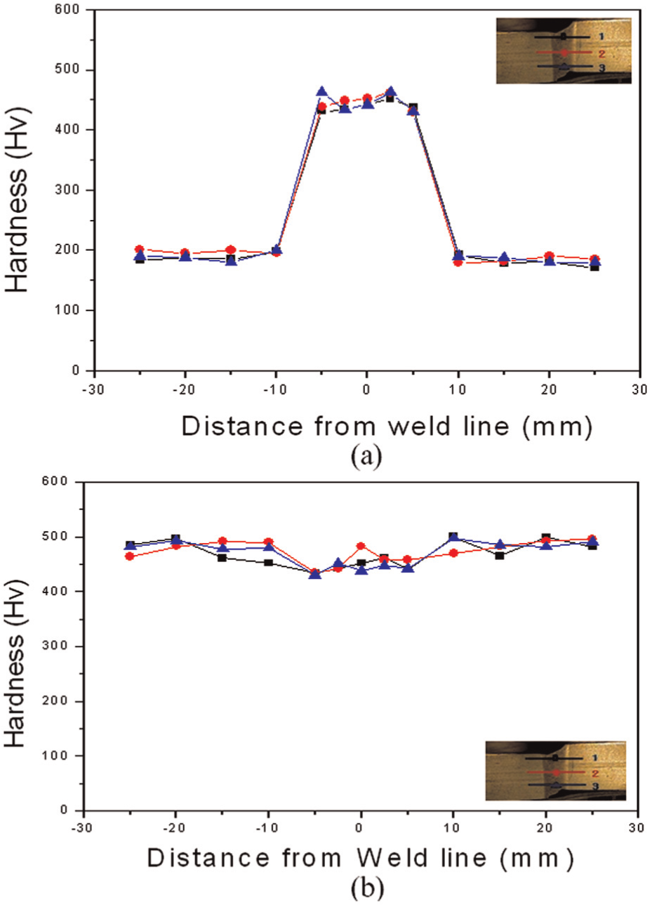
Distribution of the Vickers hardness according to the coating layer: (a) before die quenching of LWB boron steel with Zn-coating layer and (b) after die quenching of LWB boron steel with Zn-coating layer.
Evaluation of micro-cracks according to the heating time
Figure 16(a)–(d) shows the condition of the specimens and micro-cracks of the coating layer when die quenching was carried out after heating at 950 °C with heating times of 2, 5, 10, and 20 min, respectively, for Al–Si-coated and Zn-coated boron steel. Figure 16 shows that Zn-coated boron steel exhibited surface peeling off in areas in contact with the bottom during heating for heating times exceeding 5 min. On the contrary, the Al–Si-coated boron steel plate only showed differences in color and did not show any surface peeling off. This is because at the Zn–Fe state, melting occurs at 950 °C, so the coating layer of the side in contact can peel off. This is why additional tests within the appropriate temperature ranges will be needed in the future.
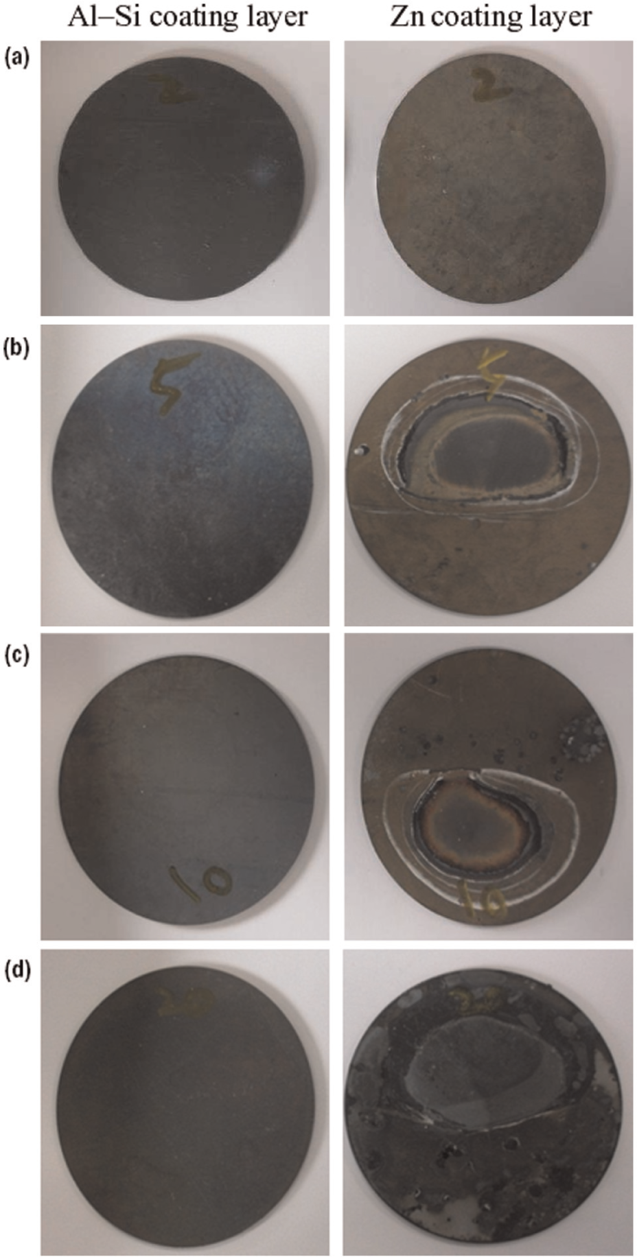
Blank states according to the heating time: (a) 2 min, (b) 5 min, (c) 10 min, and (d) 20 min.
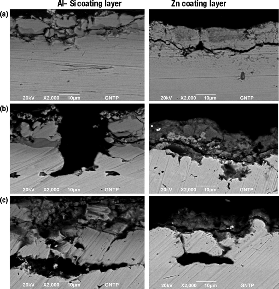
In Figure 17, each specimen was cut, and the coating layer and base metal in the cross-section were examined by scanning electron microscopy (SEM). Micro-cracks were observed in the coating layer of Al–Si-coated boron steel after 10 min. After 20 min, the cracks in the coating layer were larger.
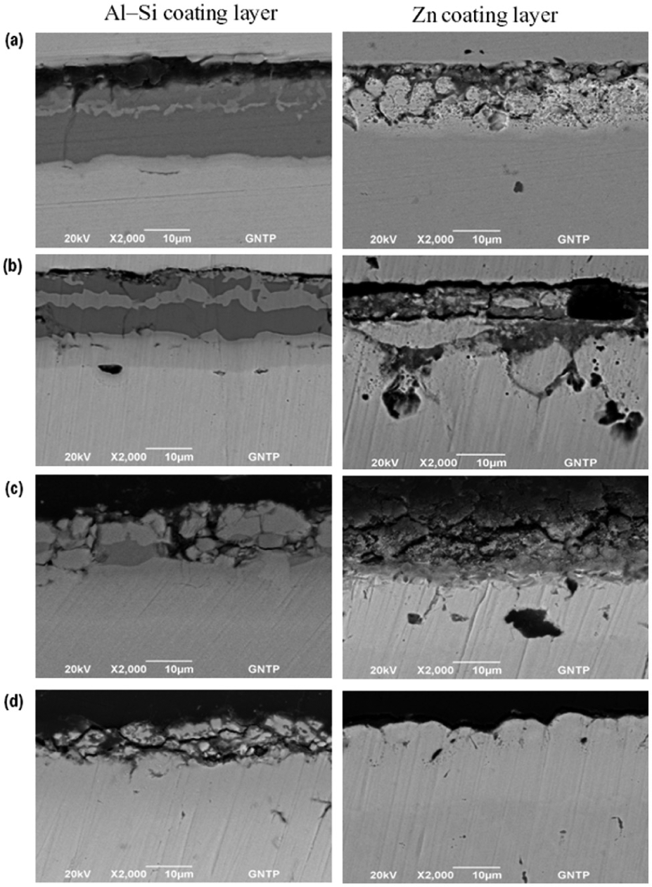
SEM images of the blank according to the heating time: (a) 2 min, (b) 5 min, (c) 10 min, and (d) 20 min.
In addition, micro-cracks were observed in Zn-coated boron steel after a heating for 2 min, after which the coating layers fell off at 5 and 10 min. Almost no coating layer remained after 20 min. Therefore, there would be problems with the products if the heating time exceeds 10 min for Al–Si-coating boron steel plates. Moreover, 2–5 min is suitable for Zn boron steel.
Evaluation of the formability and coating layer according to the punch velocity during hot forming
A formability evaluation was conducted through hot deep drawing using Al–Si-coated boron steel and Zn boron steel base metal, and LWB Al–Si-coated boron steel and Zn boron steel by setting the appropriate heating time to 5 min, as shown in Experiment 5.1. Low and high punch velocities were used as the experimental variables, and the applied pressure of the tool die holder was fixed to 15 kN. The temperature of the die and punch was set at room temperature, whereas the test specimen was heated for 5 min at 950 °C in an electric furnace, after which drawing and quenching occurred simultaneously.
Figure 18 shows the results of the test. The results showed no significant difference in the form depth according to the punch velocity at high speeds of 60 mm/s but both the Al–Si-coated boron base metal and LWB had better formability than the Zn-coated boron steel. Moreover, all the specimens had better formability for LWB than the base metal after hot forming.
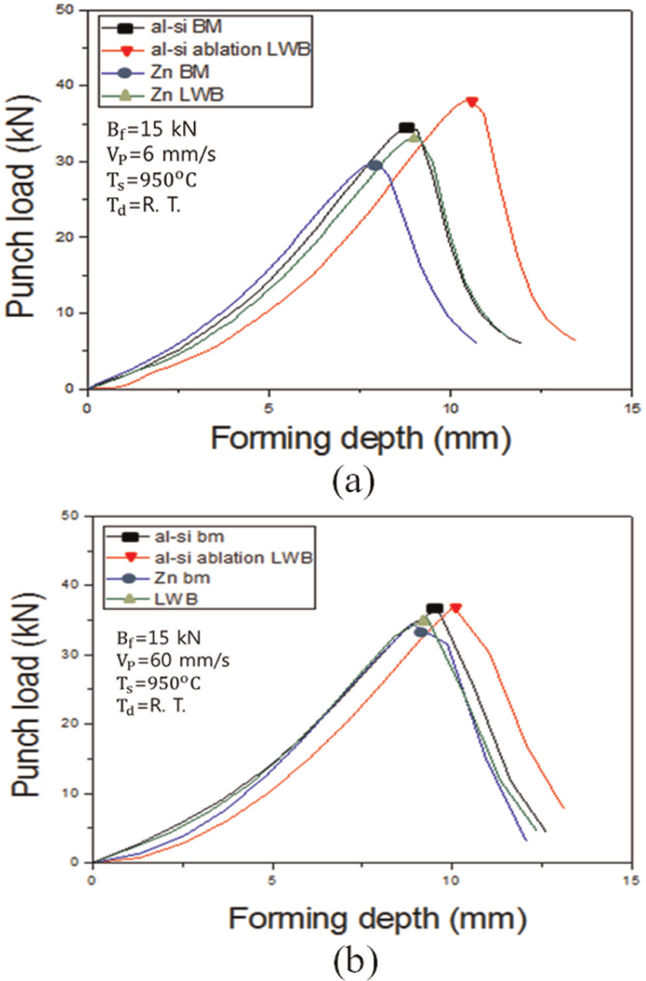
Hot deep drawing test according to the punch velocity: (a) punch velocity (6 mm/s) and (b) punch velocity (60 mm/s).
A comparison of Experiments 5.1 and 5.2 showed that compared to the Al–Si-coated boron steel, Zn-coated boron steel has poorer hardness of the welded area, specimen condition according to the heating time, appearance of micro-cracks in the coating layer and formability.
Figure 19 shows the conditions of the specimen for each experiment. The surface conditions for Zn-coated boron steel were obviously poorer than that of the Al–Si-coated boron steel. Figures 20–22 show SEM images of a cross-section for the flat side, R area, and fracture for each of the formed specimens according to the punch velocity. Figure 19 shows the measurement locations. Figure 21 shows SEM images of each specimen when the punch velocity was 6 mm/s. For all specimens, the number of cracks in the coating layer increased from the flat area to the fractured area. A comparison according to the coating layers revealed considerable peeling off of the coating layer of Zn-coated boron steel due to the thermal effects during heating and friction with the punch during forming compared to Al–Si-coated boron steel.
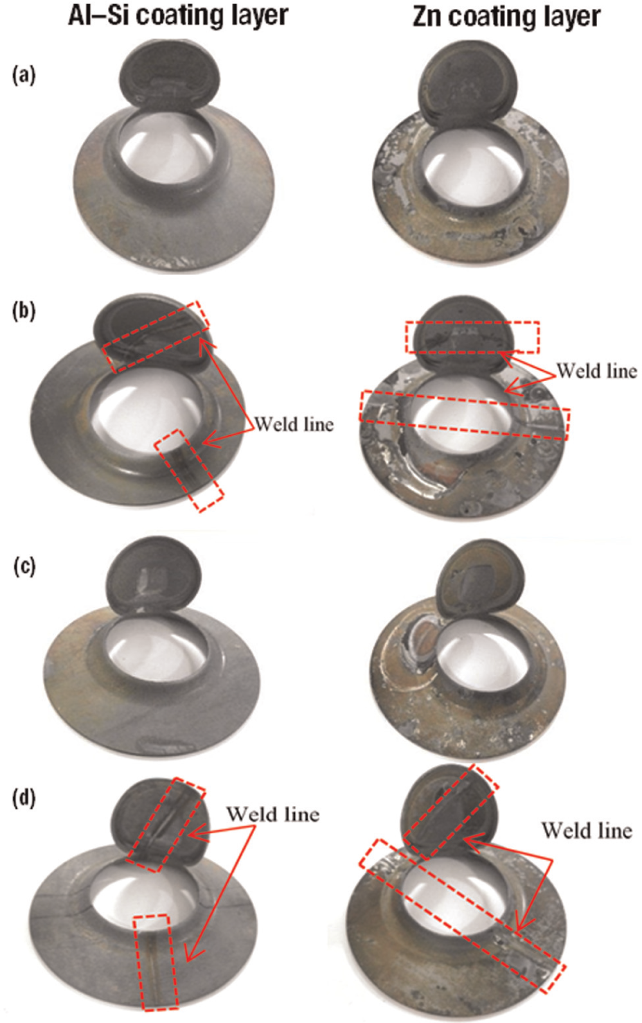
Blank of the hot deep drawing test according to the punch velocity. (a) BM (6 mm/s), (b) LWB (6 mm/s), (c) BM (60 mm/s), and (d) LWB (60 mm/s).
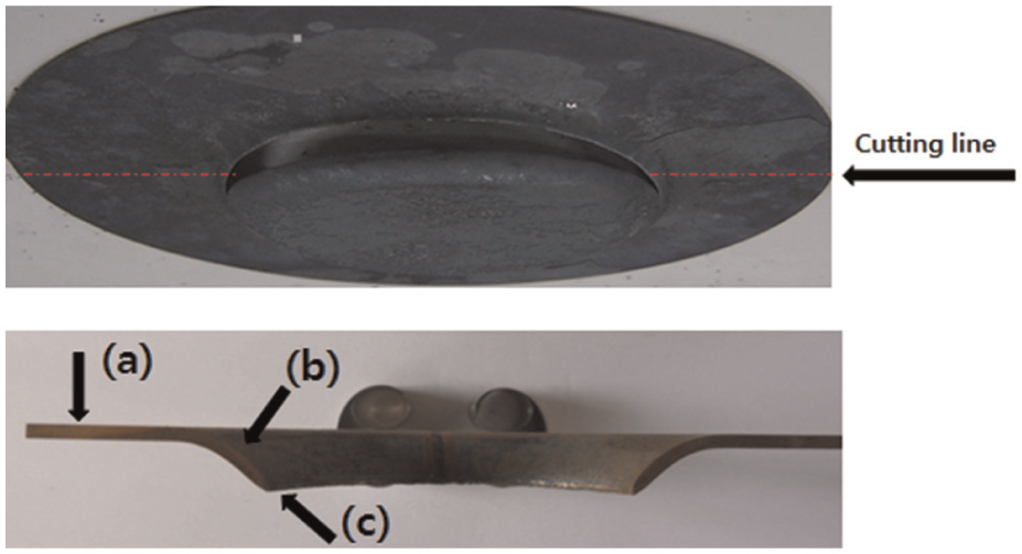
Blank position of the hot deep drawing test for SEM imaging: (a) flat surface, (b) curved surface, and (c) fracture.
SEM images of the blank according to the hot deep drawing test (Vp = 6 mm/s): (a) flat surface, (b) curved surface, and (c) fracture.
Figure 22 shows SEM images of the specimen when the punch velocity is 60 mm/s. The coating layer of Zn-coated boron steel showed cracks, even in the flat region due to thermal effects and much of the coating layer had been removed in the fractured region. Although the coating layer plays the role of lubrication during forming and the prevention of oxidized layer formation, a comparison of the formability graph in Figure 17 showed that the poor formability of the Zn-coating layer might be relevant to the effects of the coating layer.
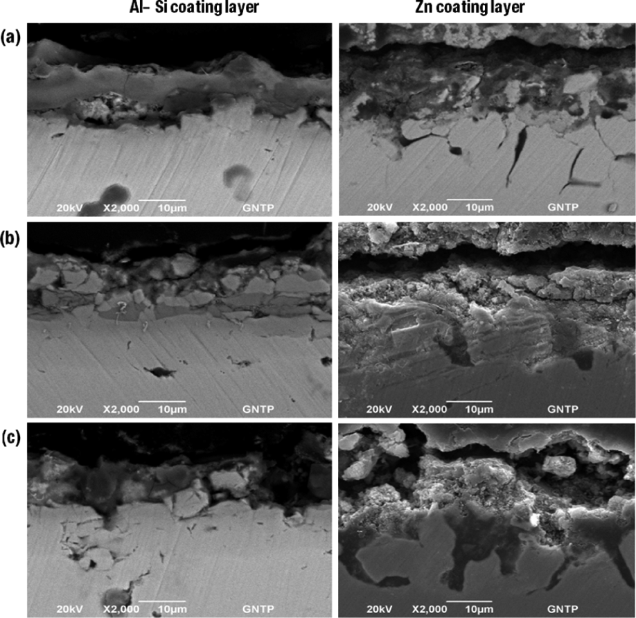
SEM images of the blank according to the hot deep drawing test (Vp = 60 mm/s): (a) flat surface, (b) curved surface, and (c) fracture.
Because the hot forming variables act together with the heating process in hot stamping, the use of Al–Si-coated boron steel plate is more suitable than Zn-coated boron steel. Nevertheless, additional experiments will be needed to evaluate the formability after heating the specimen over the temperature ranges that do not cause peeling off of the Zn coating.
Conclusion
This study examined the mechanical properties and formability of LWB to increase the collision absorptiveness by welding boron steel plates with different thicknesses to improve the disadvantages of hot stamping boron steel with poor collision absorptiveness due to the low elongation. On the contrary, during welding, the mechanical strength and hardness decreased in the welded areas due to the effects of the Al–Si-coating layer. Therefore, the mechanical properties were evaluated by dividing the specimens that had been welded under the five conditions of laser ablation for the coating layer into before and after die quenching, and the conditions of the formability and appropriate tool temperature were studied through the tool temperature variables of the hot Erichsen test. These results can be summarized as follows:
For the tensile specimen before die quenching, the condition that satisfies the tensile strength of 500–600 MPa and elongation of 18%–25% of boron steel (22MnB5) was Experiment Number 2, which had both sides laser ablated. All other specimens under the other conditions produced values that cannot be used as hot stamping components due to chemical compounds that were brittle and exhibited lower ductility. Al and Si were found in the WZ except for Experiment Number 2. Laser ablation for removing both sides of the coating layers was confirmed.
Although the Vickers hardness produced similar results before die quenching, after die quenching, the condition with both sides laser ablated produced hardness values of 450–550 Hv, whereas the specimens that were welded immediately had hardness values of 250–350 Hv.
For Zn-coated boron steel, the hardness in the welded area did not fall below 450 Hv, even when welded without laser ablation of the coating layer.
Zn-coated boron steel showed peeling-off of the coating layer when heated for 5 min at 950 °C due to contact with the bottom surface inside the heating furnace. Therefore, more research on the appropriate heating and temperature conditions will be needed.
Footnotes
Declaration of conflicting interests
The authors declare that there is no conflict of interest.
Funding
This study was supported by the human resources development of the Korea Institute of Energy Technology Evaluation and Planning (KETEP) grant funded by the Korea government, Ministry of Knowledge Economy (No. 20104010100540) and National Research Foundation of Korea (NRF) grant funded by the Korea government (MSIP) through GCRC-SOP (No. 2011-0030013).