
Abstract
This article presents a comprehensive study of material removal distribution in the polishing processes using kinematical simulation and experimental validation. The equations of material removal rate and dimensionless distribution of material removal volume are developed based on the randomly distributed abrasive grains and the kinematical–geometrical parameters of the polisher. These equations are used to generate the motion paths of abrasive grains to describe their cutting trajectories and the dimensionless distribution of material removal volume in three parameters (the crank length, rotational speed of the crank and rotational speed of the carrier). Then, the corresponding experiments are carried out to validate the numerical results. Measuring the material removal thickness of the polished hard disk substrates, the results are approximately consistent with the numerical trends. According to the demand of the polished surface, choosing reasonable geometrical and kinematical parameters can improve the machining efficiency and accuracy.
Introduction
With the development of computer science and technology, the data system of the hard magnetic disk is getting to need high density and response. In this system, the magnetic head is placed on the substrate surface, and there is a dynamic lubricating clearance, formed by thin gaseous condition, to prevent the collision between the magnetic head and the disk when starting and stopping. The minimum flying height of this clearance is less than 5 nm. Therefore, the surface performance of the hard magnetic disk has a high request for the machining process,1,2 especially in polishing, which has direct influence on flatness, waviness, surface roughness and texture orientation.1,3,4 The material removal rate (MRR) in polishing can be expressed by Preston’s equation. 4 Based on this equation, it is known that the MRR and its distribution on the substrate surface of magnetic disk mainly depend on the cutting velocity of abrasive grain while loading the uniform contact pressure. That is, both polishing velocity and direction affect the topology performance of the substrate surface. Thus, the kinematical analysis on polishing process is always an interesting topic for many researchers.3,5–12 In addition, using a finite element method, the magnetic field is evaluated to model the nano-finishing operation, which can help to better understand the magnetic field–assisted nano-finishing process. 13 However, up to now, most researchers have engaged in the kinematical trajectory curves and the average relative velocity distribution of polishing machine, and all these works are only discussed in the geometry point. Actually, in polishing, the material removal is accomplished by lots of randomly distributed abrasive grains, all of which are also regarded as the connective medium between the polisher and the substrate. If assuming the single abrasive grain as a feature point, it would be more appropriate for the investigation into the movement trajectory, cutting vestige and the material removal distribution on the substrate surface.
In this article, the movement trajectory of the abrasive grain is deeply discussed based on the kinematical model of the polisher, and the distribution model of the material removal volume was also numerically and experimentally investigated in terms of the material removal model for one abrasive grain and the random characteristics of the assumed abrasive points.
Basic kinematical equation of the polishing process for the hard magnetic disk substrate
Figure 1 shows an automatic crank–rocker polisher with the main working parts: the polishing platen, the substrate and the carrier. As indicated in Figure 2, the corresponding kinematical principle is given when polishing the hard magnetic disk substrate. The structural parameters of this polisher are listed in Table 1. In the polishing processes, the hard magnetic disk substrates are placed in the holes of the carrier, and this carrier drives these substrates to circumrotate. The movement of the polishing plate is driven through the crank–rocker mechanism, and in this polisher, the crank length E is shorter than the rocker length b. To establish the kinematical equation of the polisher with the substrates, as displayed in Figure 2, the absolute coordinate system XOY is supposed to be fixed on the base platen. Then, one relative coordinate system X1O1Y1 is created on the moving carrier, and the other one X2O2Y2 is set on the polishing platen. Consequently, the kinematical equation of one abrasive grain point on the polishing platen is introduced in detail as follows.
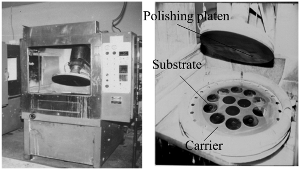
Polisher for polishing hard magnetic data disk.
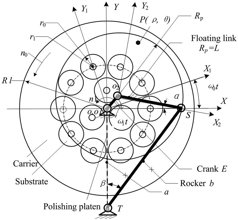
Kinematical model of the polisher.
Movement parameters of polisher.

In Figure 2, one abrasive grain on the polishing platen is assumed to be represented by the point p(ρ, θ), and its coordinate in X2O2Y2 can be expressed as
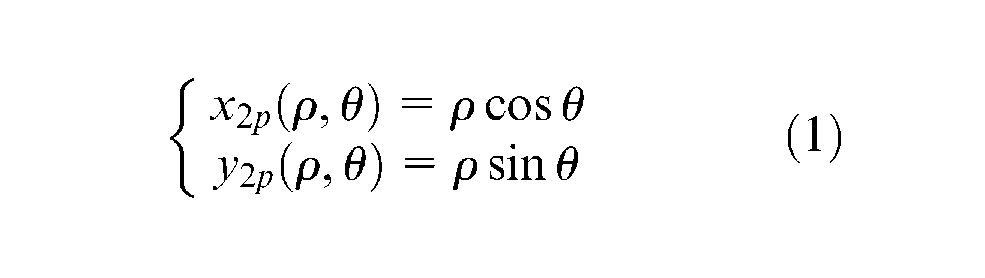
where ρ and
Using the crank–rocker mechanism and the principle of coordinate transformation, the point p(ρ, θ) is first transformed into the absolute coordinate system XOY and then transformed into the coordinate system X1O1Y1. The final movement trajectory of the point p(ρ, θ) in X1O1Y1 at time t can be given as
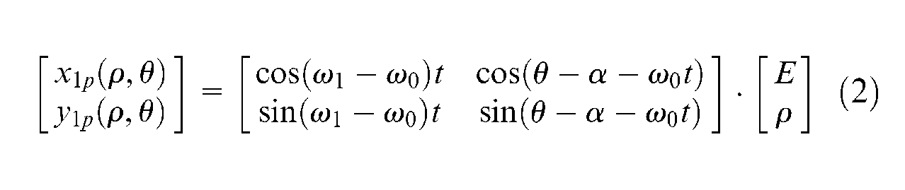
where ω0 = πn0/30 and ω1 = πn1/30 are the carrier rotational frequency and the crank rotational frequency, respectively. α is the angle between the floating link and the x-coordinate axis.
In order to obtain the relative velocity equation of the point p(ρ, θ), the derivative of equation (2) is provided as
In the above equations, ρ∈ [0, Rp] is the radius of the random abrasive grain point p(ρ, θ), and θ∈ [0, 2π] is the initial angle of the random abrasive grain point p(ρ, θ). α is yielded as
where
Note that the other geometry parameters of these above equations can be found in Figure 2 and Table 1.
Cutting trajectory equation and distribution model of the material removal volume
In the polishing processes of the hard magnetic substrates, the polishing slurry, composed of Al2O3 and chemical reagent, is regarded as a kind of medium between the polishing pad and the substrate surface. The abrasive grains in the polishing slurry, which imbed in polishing pad surface, are considered as special abrasive grain points, and these grains can make the two bodies interact with each other to generate the desired substrate surface. The whole process of removing material is finished by a great number of randomly distributed grains. Given that the spacing of two neighboring grains conforms to uniform distribution, and the protrusion height of these grains obeys Gauss distribution. Considering the grains as lots of independent points, the polishing processes can be simulated to machining the substrate using the statistic method. Actually, Monte Carlo method 14 had fully used the statistical feature in the random experiments, and they supposed the pseudorandom number technology of computer combining with the experiments to facilitate modeling the polishing. Simulation works are carried out under the environment of MATLAB 15 software system. For simulating the polishing processes of the substrates, the establishment of the corresponding equations for the cutting trajectory and the distribution model of the material removal volume on the substrate surface are given in the following.
Equations of cutting trajectory of abrasives
In polishing, the cutting trajectories of the abrasive grains have a significant influence on the texture orientation of workpiece surface, the polishing efficiency and the wear type of polishing pad.3,9,16 However, the polishing practices and theory researches have shown that the polishing effect can be improved, while the cutting trajectories randomly overlap rather than only repeat. That also depends on the curvature radius of the cutting trajectory but not the singular point. Meanwhile, the veins of the substrate surface produced by polishing dominate the gap of the hydrodynamic pressure clearance between the magnetic disk and the magnetic head in the magnetic disk storage system.1,2 Equation (2) can express the cutting trajectory of one abrasive grain in polishing. Therefore, the cutting trajectories can be simulated by taking random abrasive point p(ρ, θ) in interval ρ∈ [0, Rp], θ∈ [0, 2π] in equation (2). Through this simulation, the final texture of the substrate surface can also be predicted by overlapping several abrasive grit trajectories.
Model of the dimensionless distribution of the material removal volume
There are some models, such as experimental model, friction wear model and analytical model,3
–13,16–21 to describe the MRR in polishing with a soft pad. Based on these models, it can be known that the MRR
where HW is the hardness of the polished workpiece. Vp(ρ, θ, t) is the relative velocity between one abrasive grain and workpiece.
Since the hard magnetic disk substrates are fixed in the holes of the carrier to be machined, all the abrasive grains located on this carrier hold the same radius and axial symmetrical feature in a polishing period T. In order to obtain the model of the material removal volume distribution on polishing substrate surface, the carrier radial region [0, R1] is first separated into N intervals
where
From equation (6), the dimensionless distribution of the material removal volume (DDMRV)
where tijk is the running time, which means the jth abrasive grit has passed through the ith interval
Since the magnetic disk substrates are imbedded in the holes of the carrier during the polishing process, the relative material removed distribution ZRV(i) on the carrier surface can reflect the material removal volume distribution on the substrate surface.
Simulation and analysis on the polishing process of the substrate
Cutting trajectories of abrasive grains
Lots of different points, representing abrasive grains, are randomly arranged to obtain the simulated effects on the cutting trajectory that resulted by the movement parameters, such as the crank length E, the crank rotational speed n1 = 30ω1/π and the carrier rotational speed n0 = 30ω0/π. The jth abrasive grain is indicated by pj(ρj, θj) in the polar coordinate, and its location is placed on the surface of the polishing pad based on the uniform distribution in [0, 2πmgρ], where mg is the distribution density of the grains. Note that the numerical calculation is processed at the uniformity pressure. Calculating the coordinates of these proposed grains, the trajectory of one single abrasive point and the superposition effect of several abrasive grains can be observed.
It can be found in Figure 3 that each curve presents the movement path of one abrasive grain in the simulated parameters. Figure 3(a) illustrates the cutting trajectory for three geometrical parameters in the carrier speed of 8.5 r/min and the crack speed of 120 r/min. As the length of the crank increases, the distribution of path curves becomes uniform in the estimated area. At the crank length of 40 mm and the crank speed of 120 r/min, another three motion paths are plotted for the carrier speed of 3, 8.5 and 15 r/min. Different from Figure 3(a), these curves are generated in the same area. However, their distribution density is increased with the decrease of the carrier speed. Similarly, as shown in Figure 3(c), high crank speed can improve the superposition effect of the motion trajectory while the length of the crank is 40 mm and the carrier speed is 8.5 r/min. For one single abrasive grain, big crank length, low carrier speed and high crank speed can improve the polishing effect.
Cutting trajectory of one single abrasive grain: (a) E = 40, 80 and120 mm; (b) n0 = 3, 8.5 and 15 r/min; and (c) n1 = 30, 60 and 120 r/min.
The cutting trajectories of multiple abrasive grains are simulated in Figure 4 for two sets of parameters, and these trajectories overlap each other on the carrier surface over irregular direction. Just as simulated in this figure, the material removal in polishing processes is accomplished by the repeated cutting effect of many abrasive grains. In consideration of the even wear of the polishing pad, it is required that the curvature of the curve path should be big as much as possible to make the superposition appear in a larger polishing area. To reach the better polishing effect on the magnetic disk substrate, it is suggested to increase the crank length and the rotational speed of the crank and reduce the rotational speed of the carrier to some extent.
Cutting trajectories of multiple abrasive grains (left: E = 40 mm, n0 = 8.5 r/min, n1 = 120 r/min; right: E = 60 mm, n0 = 5 r/min, n1 = 82 r/min).
DDMRV
To achieve the uniform planarization over the substrate surface, the transient MRR or the average material rate in a polishing period is expected to be constant. The DDMRV for the carrier is calculated in equations (3) and (7) to discuss the effect of the polishing parameters on the material removal volume. While the polished magnetic disk substrates are embedded in the holes of the carrier, the distribution states of the material removal volume can also be obtained. As shown in Figure 5(a), it can be found that the calculated DDMRVs on the carrier surface present nonlinear undulation for five crank lengths. Some curves increase at first and then decrease with the increase of the carrier’s radius. On the contrary, others present the opposite tendency.
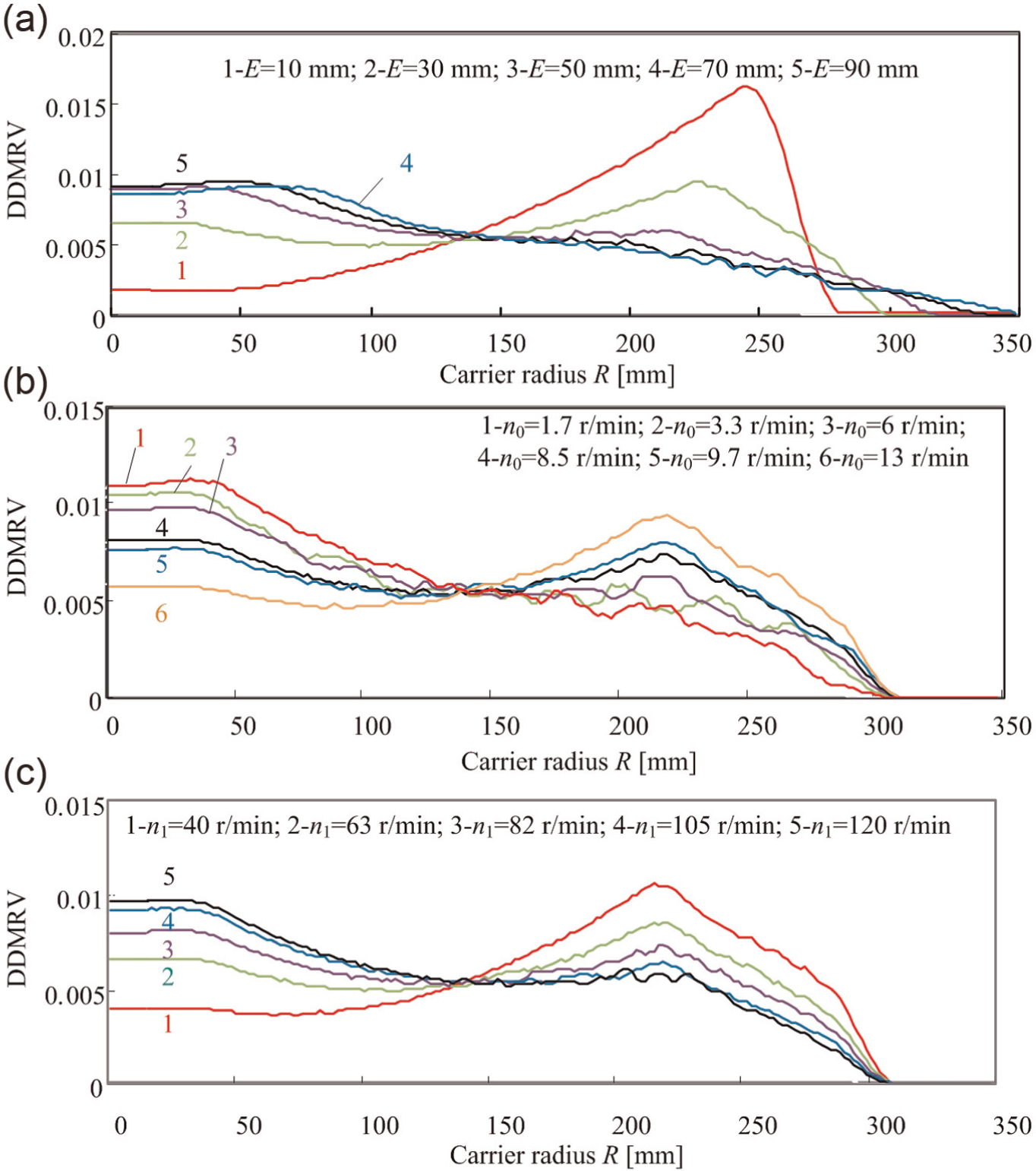
Effects of polishing parameters on the DDMRV: (a) n0 = 8.5 r/min, n1 = 82 r/min; (b) E = 40 mm, n1 = 82 r/min and (c) E = 40 mm, n0 = 8.5 r/min.
In Figure 5(a), there is a uniform region in the carrier radius to make the DDMRV keep approximate constant for each simulated crank length, and this region will transfer with the increase of the carrier’s radius. A similar uniform region can also be found in Figure 5(b) to balance the material removal volume. However, the region of the DDMRV gets smaller when the rotational speed of the carrier goes up to 13 r/min. The results affected by the rotational speed of the crank are plotted for five sets of parameters. The DDMRV becomes bigger as the rotational speed of the crank increases from 40 to 120 r/min at the beginning, and this region will transfer with the carrier’s radius. In polishing processes, it is possible to improve the uniformity of the DDMRV on the carrier’s surface while adopting proper kinematical and geometrical parameters of the polisher.
Experimental results and analysis
The polishing experiments were carried out on the polisher, as shown in Figure 1, and 13 pieces of 3.5-in-hard magnetic disk substrate were placed in the carrier’s holes for each polishing period of 3.5 min. Among that, 10 pieces were placed in the area of the carrier radius R = 172.5 mm, and others were in the area of the carrier radius R = 62.5 mm. The polishing slurry is the mixture of chemical reagent and Al2O3 abrasive, and the Al2O3 holds 5 wt% concentration and 200 nm average diameter. The pH value of the slurry is between 4.5 and 5, and the supply flow flux is 250 mL/min. In order to prevent the relative movement between the substrate and the carrier in polishing, the substrates were fixed in the inside surface of the carrier holes. Same thickness of the carrier and the substrates can balance the loaded pressure across the whole surface of the substrate. The forced cylinder pressure for the polishing disk is 80 kPa. The centerline of the carrier with the substrate was labeled to be the measuring direction. Using the γ-ray thickness gauge of Fischi Ins 303-683-0781 with the resolution of 0.025 µm, the thickness of the NiP layer was measured prior to being polished, and this value was recorded as a reference thickness. Then, the same operation was conducted to calculate the removed thickness of the substrate after the polishing processes.
The micro-texture on the substrate surface is illustrated in Figure 6(a) and (b), which show that the cutting vestiges are generated by lots of abrasive grains’ crossover and overlap. It can be found that some cutting vestiges are truncated by other cutting vestiges and obstructed by the plasticity bulges. This surface texture is produced by the cumulative effect of several grains in different times and directions, and it is consistent with the simulated cutting trajectories of grains.
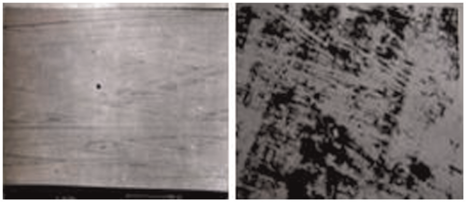
Surface micro-texture of polished substrate.
The measured material removal thickness of the substrate surface is listed in Figure 7 for kinematical and geometrical parameters in the polishing process. The presented points in this figure are the average values of six polishing experiments for each set of parameters. The measured values for material removal thickness in the inner and outside diameters of the substrate are discarded to reduce the possible borderline effect resulted by the uneven distribution of the polishing contact pressure. It can be seen in Figure 7 that the actual material removal thickness gets bigger as the tested parameters become larger, such as the crank length, the rotational speed of the crank and the rotational speed of the carrier. The change trends of the material removal thickness with the carrier radius are approximately consistent with the simulated results. The experimental results indicate that the simulate method is helpful and feasible to optimize the kinematical and geometrical parameters in the polishing processes.
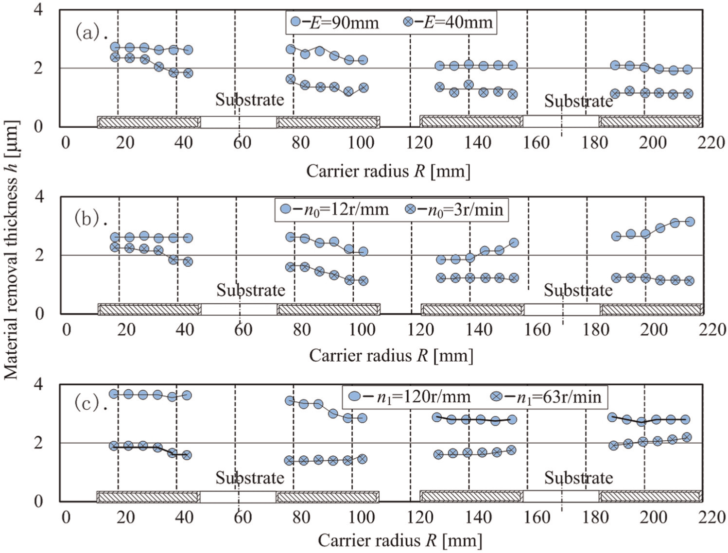
Effects of polishing parameters on the material removal thickness of the substrates (top: n1 = 82 r/min, n0 = 8.5 r/min; middle: E = 40 mm, n1 = 82 r/min; bottom: E = 40 mm, n0 = 8.5 r/min).
Conclusion
The established equations for the cutting trajectory in this article can describe the movement of the abrasive grains in polishing processes. The simulated trajectories by the equations are basically consistent with the veins displayed on the polished surface. Using the model of the DDMRV can calculate the material removal volume to analyze the effect of the kinematical and geometrical parameters of the polishing machine. An agreement was achieved between the simulated and experimental results. It is found that increasing the crank length, the rotational speed of the crank and decreasing the rotational speed of the carrier can improve the distribution uniformity of the material removal volume.
Footnotes
Declaration of conflicting interests
The authors declare that there is no conflict of interest.
Funding
This study was supported by the Chinese National Natural Science Foundation (Grant No. 50875179).