
Abstract
The factors that affect the life of continuous steel casting rollers were investigated. Rollers that were removed from a manufacturing line because they had failed were renovated by submerged arc welding and subjected to working conditions until they again failed. The welding parameters (welding current, welding voltage, welding speed, current polarity, preheating temperature, interpass, postheating, and cooling conditions of clad) and chemical reactions and compositions had important effects on roller lifetime. Chromium has a dominant influence on the abrasion resistance of hard martensitic structures of the roller. Cr produces several types of precipitates (M3C, M23C6, M7C3, and M3C2). Alloying elements Mo and V in welding wire form fine carbides Mo2C and VC in weld layers. In low-carbon welding wires, precipitation hardening by N2 is used, by formation of chromium nitrides CrN and Cr2N. This article analyzes the process of failure of the functional surfaces of the repaired roller, in order to identify the origin and propagation of the cracks and share of corrosive environment on the tribo-degradation processes.
Introduction
Continuous casting is an important step in steel processing. It is performed by running a sheet of nearly molten steel through a series of cylindrical casting rollers that press and cool the steel into a slab that can be further manipulated down a manufacturing line. It is important to care for the rollers in this assembly to ensure reliable operation and quality steel output. Continuous casting rollers are composed of heat-resistant low alloyed steel that resists deformation (creep). Unfortunately, the common types of steel for these rollers, C-Cr-Mo type 41CrMo4 (EN 10083-1-91) and C-Cr-Mo-V type 1.7733 24CrMoV55 (EN 10083-1-91), still break down under the high stress of casting. During steel production, rollers are subjected to high-temperature corrosion and wear from thermal fatigue when moving and cooling slabs from 1280 °C to 850 °C. These combined stresses cause rapid wear to the surfaces of new rollers. The influence and intensity of wear vary by the roller’s position in the line—whether it is at the top, curved middle, or bottom section of the device.
From a tribological point of view, rollers are loaded by adhesive–abrasive wear. Adhesive wear occurs at the point of contact between the roller and the steel slab. Micro-welds occur that reduce plastic deformation, and low-cycle fatigue finally causes the material layers to separate. Abrasives such as residual casting powder and corrosive products can groove the roller surfaces. The extreme operating environment of the casting rollers causes free hydrogen ions to react with high-fluorine slag. The corrosion forms pits on the surfaces that serve as the origins for fatigue-induced cracks. Corrosion is also promoted under high-temperature stress by chlorine in the cooling water in the fatigue cracks.1,2
The start of corrosion processes is also supported by chemical reactions with residues of casting, coating, and insulation powders that act on the surface of the roller as abrasives. The utilization of casting powders based on CaO, CaF2, SiO2, MgO, and Al2O3 in the steelmaking process is necessary because of their impact on the slab surface and steel grade quality. Continuous casting rollers operate in an extremely hard environment that causes a reaction of free hydrogen ions with high-fluorine content slag coming from powders containing fluorspar (CaF2). On the surface of the roller, corrosion pits are created as preferred centers of fatigue corrosion and fatigue cracks.
Depending on the hardness of the environment, the material’s resistance declines 2- to 25-fold. The amount of stress depends on the thermal gradient and thermal expansion of steel in the surface layers of the rollers.
Certain practical criteria determine when a roller is removed from operation.3–5 If a magistral crack goes deeper than 1 mm, which is beyond the weld overlay, or a corrosive-fatigue crack goes deeper than 4 mm, the roller has failed and must be removed.6,7 The maximum overall wear should be 12 mm of the roller diameter or 2 mm of the journal diameter before renovation. After renovation, the worn rollers can be reinstalled into the continuous line.
Currently, there are two arc welding technologies used for the roller renovation: submerged arc welding (SAW) and flux-cored arc welding (FCAW). In this article, we focused on SAW, a process which heats metal wire with a buried arc between a bare electrode and the work. The arc and molten metal are “submerged” in a blanket of granular fusible flux during the process.
The choice of welding metals has an important effect on the quality of the repaired rollers. In metals with lower carbon (0.03%–0.07%) and chromium contents (13%–17%) which have a martensitic–ferritic structure containing up to 10% of ferrite, missing carbon is replaced by nitrogen in the chromium cladding layers. The hardness of these layers, therefore, increases through the formation of CrN and Cr2N in the structure. Nitrides in the cladding block dislocations, grain growth, and formation of Cr23C6 at grain boundaries, thereby reducing the welded repairs’ resistance to thermal fatigue, creep, and aging. Furthermore, the nitrides reduce the Ms (martensite start) temperature, which causes fine-grained martensite to form in the cladding and heat-affected zone during solidification. Normally, a third-generation cladding material, UP5-GF-45-C DIN 8555, is used that can form Cr2N with a consequent reduction of the Ms temperature to around 200 °C. 6
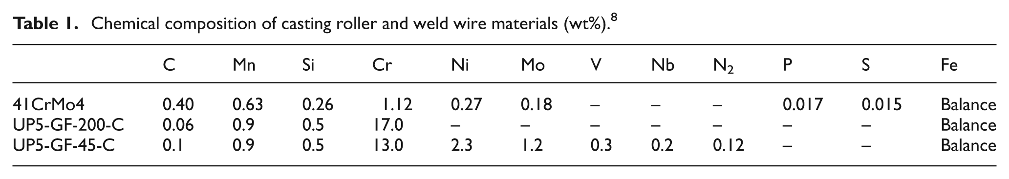
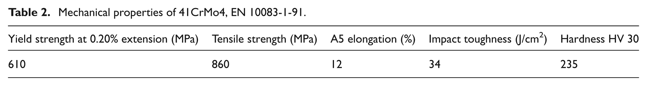
Herein, we present an analysis of the properties of SAW renovated ∅240 mm rollers and discuss the reasons for their failures. Their surfaces and cracks were analyzed after removal from operation. These rollers operated in a curvilinear section of a continuous casting line and were composed of 41CrMo4 steel (EN 10083-1-91). The steel’s chemical composition and mechanical properties are given in Tables 1 and 2.
Chemical composition of casting roller and weld wire materials (wt%). 8
Mechanical properties of 41CrMo4, EN 10083-1-91.
Analysis of continuous steel casting roller failure
The rollers’ surfaces change shape by separation of the particles due to friction, leading to separation of layers and surface cracks (Figure 1). Friction causes the rolled material (steel slabs) to slip resulting in further friction that roughens the roller surfaces and they wear out. 9 According to Boyes theory, friction is not linearly dependent on the hardness of the base surface but on the final hardness after hardening during wear. The relationship between hardness and abrasion resistance is defined by Wusatowsky’s equation below
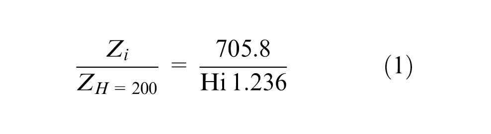
where Zi is the wear of work layer Hi, in Brinell units, and Z is the wear at work layer 200 HB.
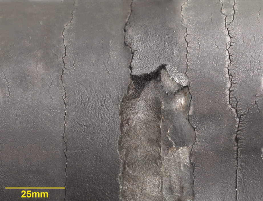
Photograph showing the nature of surface failures on caster rollers renovated by arc welding technology.
According to the Hertz theory, the greatest stress resulting from pressure on the rollers is not at the surface but at a depth of 0.8 × b, where b is the width of the roller contact. The stress caused by friction, greatest at the surface, must be added to this stress. Frictional stress gradually decreases toward the roller center. By superposition, the maximum stress level is at the surface of the rollers. To the stress produced by the friction, one must add the stress induced on the roller surface by bending. 9
During operation, rollers are subjected to cyclic stress, causing changes to the structure of the metal layers and properties of the functional surfaces. Heterogeneity (inclusions) in the cladding negatively affects the lifetime of the rollers. In new rollers, the base material is very pure and they keep working under the stressful loads for a long time. Rollers that have been renovated by arc welding have much more heterogeneity in their surface layers. The electro-slag welding technology presented in this article led to silicate inclusions that were identified as the starting points for working-surface failures.
The roller’s work surfaces are subjected to cyclic stress in a corrosive environment.1,9 This environment significantly reduces the material’s resistance to fatigue. Additionally, high temperatures (800 °C–1200 °C) cause thermal fatigue. This multiaxis stress creates cracks. The depth of the cracks increases gradually in a pattern called mosaic mapping (Figure 2). Due to the friction, the metal peels near the cracks. The central cooling system of the roller is presented in Figure 3. The aim of the research was to determine the extent of roller damage with an emphasis on the creation and spread of the magistral cracks (mapping), whether it is a crack extending into the base material or into the melted area or into the weld metal of the first layer or interlayer. In addition to studying the shape and crack propagation, the presence of corrosive products in the vicinity of the cracks was also determined. The research was also aimed at the evaluation of the impact of heterogeneity of the weld layers on crack initiation, the presence of carbide inclusions at the locations of the layer failure, and their influence on crack initiation. This was monitored by energy-dispersive X-ray (EDX) analysis, but this was not confirmed since it was fine-grained fine-dispersed carbides.
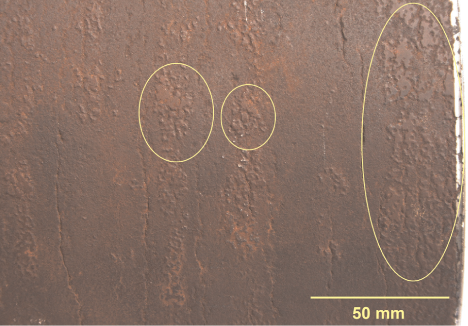
Detail of roller surface with corrosion products and micro-welds on surface (scale).
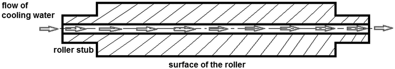
Diagram of a continuous casting roller with cooling device.
Materials and methods
Roller renovation
Worn rollers that had cracks and unacceptable wear-induced deformation upon inspection were removed from operation and designated for repair.10,11 The surfaces of the worn rollers were inspected visually and ultrasonically to decide whether they could be repaired. Based on the nature of the defects, each roller’s eligibility for renovation was assessed.12,13
Rollers deemed suitable for renovation, were degreased and preheated in an electrical oven to 280 °C. The surfaces of the preheated rollers were welded in three layers by SAW. Welding was done in the horizontal position, according to STN EN ISO 6947 on the Ferromont welding device (Figure 4). The Ferromont welder rotated the rollers during welding. Weld wire was fed by a welding head, which oscillated along the length of the cylinders. Weld wire passed through a layer of flux in the jig. Three layers were welded onto each roller as described below. During welding, the rollers’ temperature was maintained by flame heating. After welding, the cylinders were allowed to anneal for several hours to reduce stress and then slowly cooled by isothermal wrap. The heat treatment was followed by turning, boring, and grinding the roller surfaces to the required dimensions. Finally, the rollers were inspected by ultrasound and stored.
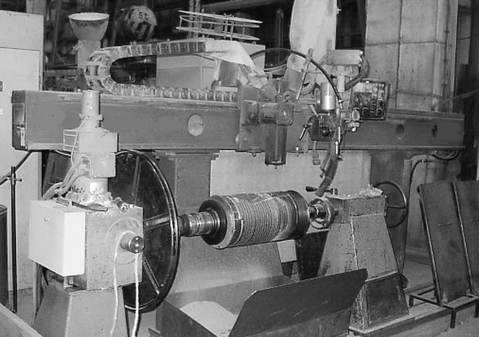
The experimental apparatus for cladding the continuous casting rollers and rolling mill rollers.
Welding materials
The analysis was performed on the claddings made with welding wires currently used in the renovation of rolls. Welding parameters, thermal welding mode (preheating, interpass, and postheating) and subsequent heat treatment were chosen in accordance with the recommendation of the manufacturer of welding wires and a valid Welding Procedure Qualification Record (WPQR) for the renovation of the rolls.
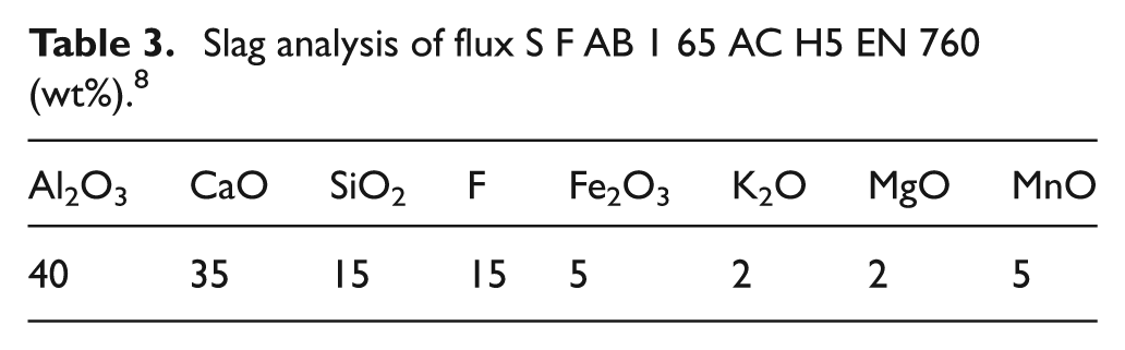
The hardness of the welding metal stated by the manufacturer was 190 HV 30. The inner layer consisted of weld wire (UP5-GF-200-C DIN 8555) with alumina-basic flux (S F AB 1 65 AC H5 EN 760). Their chemical compositions are given in Tables 1 and 3. Before arc welding, the flux was dried at 300 °C for 1 h. The flux had a basicity index of 1.3 and grain size ranging from 0.2 to 2.0 with a density of 1.2 kg/dm 3 . The polarity was DC+, and the diffusible hydrogen content (HDM) was below 5 mL/100 g. On top of the inner layer, two cover layers were welded with wire (UP5-GF-45-C DIN 8555) and alumina-basic flux (S F AB 1 65 AC H5 EN 760) (Figure 5). Their chemical compositions are shown in Tables 1 and 3. The hardness of the welding metal specified by the manufacturer was 450 HV 30.
Slag analysis of flux S F AB 1 65 AC H5 EN 760 (wt%). 8
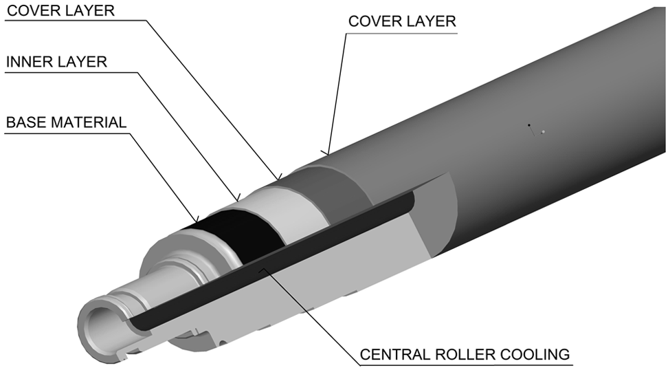
Scheme of layers deposited on roller.
Welding conditions
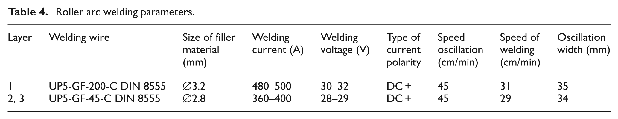
The technical parameters of the welding are listed in Table 4. Before welding a roller, it was preheated to 260 °C–270 °C. The interpass temperature during welding was 200 °C–380 °C. The welded roller was heat-treated by annealing to relieve stress at 520 °C (±10 °C) for 4–5 h. This was followed by cooling at the rate of 40 °C/h to 210 °C in isothermal wrap. From 210 °C, the roller was cooled in air. The twist of the interpass (weld seam) was 10–12 mm. The wire offset was 30–40 mm (Figure 6). The required quality level was STN EN 25 817 “B.” The quality of the weld overlay was assessed by visual examination according to STN EN 970, a capillary test according to EN 1289, and ultrasound according to STN EN 1712.
Roller arc welding parameters.
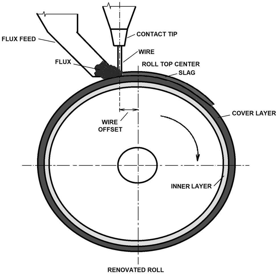
Scheme of welding wire position. (Adapted from McKay, 2000). 14
Metal analysis
Metallographic analysis of cracks was made on a worn roller (Figure 2) according to STN EN 1321. The analysis of individual welded-on layers was carried out on cross sections of the examined samples. Structure evaluation and documentation were performed with a ZEISS NEOPHOT II light microscope and Hitachi S-450 scanning electron microscope. Chemical analysis of welded layers and their phase transitions was carried out by energy-dispersive spectrometry (JEOL JSM-35 CF) and a LECO analyzer.
Given the content of Cr in the examined materials, an etchant was used to visualize the microstructure of materials. The etchant had the following composition: 0.3 mL methanol, 0.3 mL HNO3, 0.3 mL HCl, 0.2 mL picric acid, and 0.1 mL glycerol. Samples were exposed to the etchant for 15 s. The average hardness measured of base material was 234 HV 10, heat-affected zone was 293 HV 10, and top layer of cladding was 432 HV 10.
Before renovation, it was important to take into account all characteristics of the renovated material, which could have negatively impacted the quality of the final weld. Failure to consider certain parameters or measuring the wrong qualities could lead to economic losses. Therefore, before renovation, it was necessary to define the susceptibility of materials to under-weld, annealing, and lamellar cracks. It was also necessary to take into account the effects of heat on the isothermal transformation diagram and continuous cooling transformation diagrams.
Results and discussion
The microstructure of the damaged roller weld is documented in Figure 7. On the scratch pattern, it is possible to observe the multilayer dendritic structure of the weld metal, which was crossed by the intergranular crack. The crack is ended by the horizontal branching in the area of the coarsened grain in the under-weld heat-affected zone.
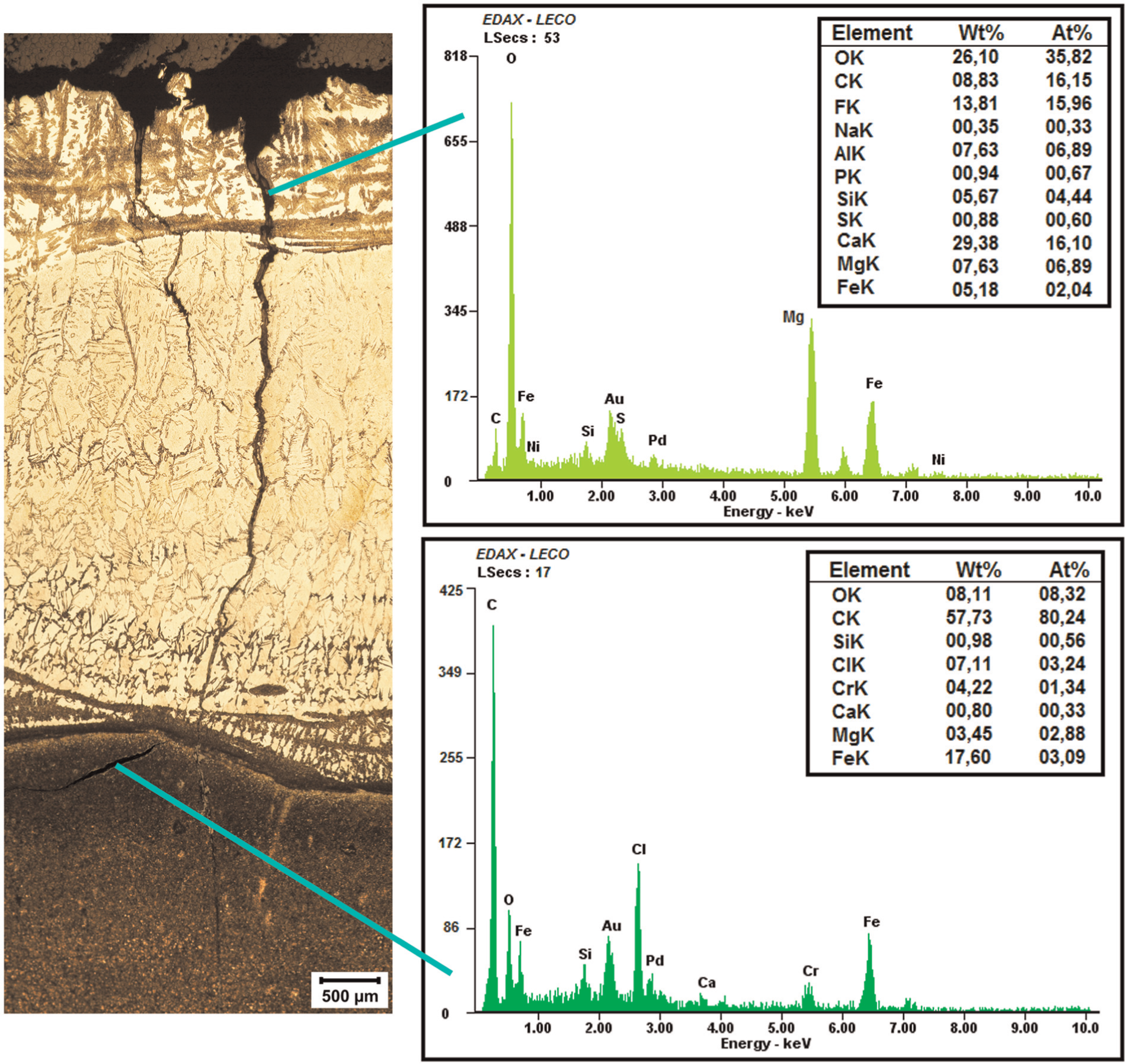
The microstructure of the weld metal with magistral crack with chemical EDX analysis.
The roller surface was segmented in strips representing each wire oscillation as the weld was laid down. EDX analysis confirmed that the individual segments had oxide layers. Metallographic cuts from the surface to the heat-affected zone on the dendritic grain boundaries pointed to cracks formed by the chain method. These intercrystalline cracks spread horizontally, parallel to the roller surface, between the heat-affected zone and the base material. Most likely, they were formed by stress at high temperatures. The impact of stress was also reflected in the substructure, that is, the sub-grain network in between the polyhedric columnar coarse grains. EDX analysis confirmed the presence of polycomponent oxides, fluorides, and metal elements in the cracks passing through the weld zones. Their compositions were consistent with the weld material and aluminum-basic flux S F AB 1 65 AC H5 EN 760. An EDX analysis of the individual layers also showed that the welding metal had the proper chemical composition under the ion theory of SAW.
The weld layers failed due to several factors, the dominant of which was thermal fatigue, as evidenced by the complex damage to the roller. The thermal loading of the roller surface was affected by the cooling system and the time the roller was in contact with a hardening metal slab. Sulfidic interstices can contribute to degradation, but this was not the case in our examinations.
For the new 41CrMo4 continuous casting rollers, the thermal cycle initiates degradation. 15 This roller material has a fine-grained martensitic structure to resist heat (Figure 8). The functional part of the roller is heat-treated to the depth of 4–6 mm by surface quenching, which adds carbidic particles that increase resistance to abrasion. The surface undergoes several changes that lead to equipment failure. In the first stage, if the contact surface of the roller and slab reaches a temperature of about 200 °C, Fe2,4C transition carbides precipitate, changing tetragonality. These semicoherent carbides form in hexagonal grids with minimal energy demands. Effectively, carbon atoms are redistributed in solid solution. As temperature rises through 200 °C–300 °C, nuclei of secondary martensite are formed. Heating to 250 °C–400 °C induces the recrystallization of the solid solution to form stable cementitic carbides. As more carbides precipitate, the carbon concentration in the martensite decreases. The strengthening effect of the carrier particles cannot compensate for the decrease in hardness, thus stiffness decreases. Internal stress and defect density decrease. Heating above 450 °C causes iron atoms to diffuse, and the martensite transforms into ferrite and carbides; the material then softens. Under the influence of chromium, the layout of some alloying additions between ferrite and cementite changes. If the solubility limit of the elements with high affinities for carbon (Ti, Zr, V, Ta, Mo, W, and Cr) is exceeded, new noncementitic carbides with different lattices form in the cementite.
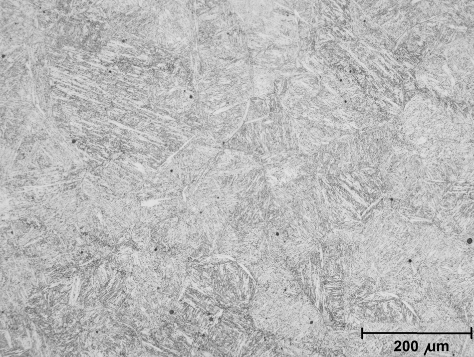
The microstructure of 41CrMo4, EN 10083-1-91.
When considering that these metallurgical factors influence the base materials of rollers with martensitic structure, it can be concluded that weld layers should have a high content of carbide-forming elements to better withstand the thermal cycles. In these layers, the decreases in hardness and strength are slight.
The carbon content of the weld metal should not exceed 0.15% to prevent the formation of Cr23C6 at the grain boundaries. Such a phenomenon would cause the reduction of Cr in the matrix and would increase the susceptibility of the martensite structure to cracking. To stabilize the structure, the metal should contain Nb or V and also N2 in the range of 0.10%–0.20% to increase resistance to creep and thermal fatigue. The nitrogen leads to the formation of CrN and Cr2N, which increase hardness at low C contents.6,16 Nitrides block dislocations, grain growth, and formation of Cr23C6.
In addition to the wear of rollers’ working surfaces, their journals wear out, but the requirements for choosing the repair materials are different. The journals should be tough and resistant to breakage and resistant to the action of the coolant. Thanks to the nitrogen content in the weld wire due to dispersed nitrides in the cladding layer, the life of the rollers was extended by 17% compared with rollers renewed by wires of the previous generation without nitrogen. 6
Conclusion
During rapid heating and cooling of the surface layers, the metal expands producing compressive stress on the cooler subsurface layers. When the stress reaches the yield point, the surface layer tries to strip off and deform. The tendency to form cracks due to the alternative stresses increases with more rapid heating and cooling.
Based on the theoretical wear analysis, the materials for the renovation of the working surfaces of the continuous steel casting roller should have the following characteristics.
They should be manufactured of a solid, tough, homogeneous layer.
The cladding layer should have good plastic properties to reduce the effect of concentrated stresses.
The weld should ensure high corrosion resistance, which passivates Cr in weld metal with a Cr content over 12 wt%.
The weld layer should have low thermal expansion and high thermal conductivity.
The weld layer should be resistant to abrasive and adhesive wear.
Based on the experiments, it can be stated that cracks were spread from a functional surface and spread vertically to a depth of 4–6 mm, up to the melted area of the base material through the hard cladding layer (martensitic). At the same time, on the interface base material—interlayer, thus in the area of the most heterogeneity of materials—horizontal crack propagation occurs due to combined stress, the local pressure of the slab, causing the bend of the roller. The intersection of the horizontal and vertical cracks caused separation of large segments of the weld clads and the destruction of the roller.
EDX analysis proved the presence of corrosion products in vertical cracks caused by cooling water contaminated with casting, covering, and insulating powders containing fluorspar (CaF2), which is in operation where it is sprayed onto the roller surface by jets. This indicates a high content of Ca and F as the oxide compounds. The horizontal cracks do not contain these elements.
Some of these requirements may be contradictory, but it behooves the engineer to satisfy as many requirements as possible. For abrasion resistance and hardness of the renovated surface layers, it is necessary to ensure that the tough, more plastic matrix of the base metal contains hard fine-grained Cr carbides.
Currently, research focuses on innovative applications of materials with specific chemical compositions to particular sections of continuous casting lines. Economics also plays an important role in renovation with the aim of minimizing the number of operations and conserving materials—flux, gas, and so on. New trends in the development of materials for FCAW methods are making them an attractive method for roller repair.
Footnotes
Declaration of conflicting interests
The authors declare that there is no conflict of interest.
Funding
This work was supported by scientific grant agency of the Ministry of Education of the Slovak Republic [VEGA No. 1/0600/13].