
Abstract
Setup planning and fixture design are two main tasks for the integration of design and manufacturing process. Setup planning identifies which features must be machined in each setup and determines locating datum for each setup, whereas fixture planning determines precise locating and rigid clamping of workpieces according to a part design and process requirements. So, a close interaction exists between setup planning and fixture design. This research deals with the problems of setup and fixture planning for the machining of prismatic parts. In the first step, a new heuristic method is presented to plan the setups with accurate respect to datum faces in design and manufacturing. Two concepts, namely, “inferiority face” and “control face,” have been used for this purpose. In the next step, a mathematical model is used to define the primary, secondary and tertiary fixture planes with respect to locators’ position. This model determines relationship between misplacement of locators and dimensional and geometrical specifications of workpiece. The main purpose of developing the model is to determine the effect of locator height error on hole position tolerance. The capability of this model is verified by simulation in “motion study” module in SolidWorks software. This approach is very useful in the hole-making process. The system is developed in Visual Basic on a SolidWorks platform. The effectiveness of the system is verified by an industrial component.
Introduction
Setup planning and fixture design, which are constrained-based problem, are the main tasks in process planning. The tasks of setup planning usually consist of (1) grouping features or operations and datum into setups, (2) sequencing the setups and (3) sequencing the operations within each setup. 1 Fixture planning determines precise locating and rigid clamping of workpieces according to a part design and process requirements. Moreover, the layout of locating and clamping points is specified in this step. 2 Setup planning and fixture design have so close relation, and limitations of fixture should apply on every setup. A brief review on setup planning and fixture design is presented as follows:
Setup planning
Setup planning routine is influenced by the tolerance relation between features, feature precedence relations and tool approach direction (TAD). Graph theory, intelligence algorithm-based and heuristic reasoning are the most common techniques used to support setup planning. Huang et al. 3 proposed a graph theoretical approach to solve the problem of setup planning based on tolerance analysis. The graph search was used to identify the optimal setup plan for rotational parts. Zhang and Lin 4 used a hybrid graph approach and matrix theory. In their research, tolerance analysis was a main factor for setup planning decision making. A systematic methodology was developed based on directed graph theory and matrix theory. Yao et al. 5 developed a systematic approach for automated setup planning with the utilization of flexible manufacturing resources. In their approach, a datum machining graph (DMG) was used for defining the part information and a feature tolerance graph (FTG) for setup information. Setup planning was defined as transforming FTG to DMG based on tolerance and manufacturing resource capability analysis. Sun et al. 1 proposed a new directed graph approach for setup planning to describe precedence constraints explicitly and used a setup precedence graph (SPG) to describe precedence constraints between setups. During the generation of the SPG, the minimal number of tolerance violations was guaranteed preferentially by the vertex cluster algorithm for serial vertices, and the minimal number of setups was achieved using variants of the breadth-first search. The main problem of the graph-based approaches is that the precedence constraints are not considered properly during setup formation.
Some researchers used intelligent algorithm to plan the setup for machining. The common algorithms such as genetic algorithm (GA), simulated annealing (SA), particle swarm optimization and ant colony have been implemented in the literatures. Kafashi 6 presented a GA-based optimization algorithm for integrating setup planning and operation sequencing problem. The outputs of his work were an optimized setup plan, an optimized sequence of the operations and an optimized selection of the machine, cutting tool and TAD for each operation. Kafashi et al. 7 used a modified particle swarm optimization (PSO) algorithm for optimizing the setup plan. The proposed approach analyzed the constraints such as TAD, the tolerance relation and feature precedence relations for determining an optimum plan. Krishna and Rao 8 developed an ant colony algorithm to optimize the operation sequence. They used a traveling salesman problem (TSP) to model the operation planning problem. In an intelligent algorithm, the method to handle precedence constraints is the penalty strategy, which is not effective in performance 1 and does not reflect the influence of precedence constraints on setup plans explicitly.
Experiential knowledge, in the form of heuristic reasoning, has also been used to assist setup planning. For example, Peng et al. 9 utilized a simple rule-based system to determine setup and fixture layout. He recognized locating planes by the fuzzy comprehensive judgment method. This information was as input to case-based reasoning (CBR) module to guide user to reach good fixture configuration design based on previous experiences. Gologlu 10 presented an automatic setup planning module with respect to fixturing constraints for 2.5D machining of near net-shaped prismatic parts. Taking machine capabilities and fixturing strategies into account, the setup planning module automatically generated multiple machining setup. Stampfer 11 tried to determine setup planes for workpiece machining with respect to all tolerances and available fixtures. He divided dimensional and geometrical tolerances into loose and strict types. His algorithm decreased tolerance constraints if the tolerances could not be satisfied with respect to available fixtures.
Fixture planning
Asada and By 12 analyzed the problem of automatically locating fixture elements using robot manipulators. They developed a kinematic model that can be used to analyze the fixture layout, deterministic locating, accessibility and detachability, bilateral restraining and total restraint. Rong et al. 13 derived a mathematical definition to describe position, profile and orientation tolerances, and then influences of locating error were considered in 3-2-1, pin-hole and V-block locating approaches. Their work was based on homogenous locating and orientation matrix. Cheraghi et al. 14 presented a mathematical approach to study the effect of datum target point variation on part acceptance. Simulation is adopted to identify the major sources of hole position error due to errors in datum targets. It was found that the datum target variation has a profound effect on the measured location of holes referencing those datums. Then, simulation results were verified by software CATIA. Qin et al. 15 developed a synthetic analysis to investigate the workpiece position error in fixture locating schemes. A general formulation of fixture modeling was proposed to establish the relationship between the workpiece position error and its source errors. Wan et al. 16 announced that errors of machine tool, fixture and datum influence on the machining accuracy of the workpiece. The objective of their article was to provide a framework for abstracting an error model that integrates three types of errors, that is, machine tool, fixture and datum errors, into a unified one. Differential motion theory was used to build the evaluation model of three types of errors.
In a brief review of the articles in setup planning and fixture design, several limitations can be mentioned that have not been considered in the literatures. These cases are as follows:
In setup planning routine, a leak of attention to feature’s topology and relations between feature positioning in manufacturing and datum planes in drawing can be seen in the literatures. A correct dimensional control and inspection just will be achieved when the workpiece locates on a plane that has been shown by blueprint dimension. In this situation, final tolerance just depends on machining process tolerance and does not need any tolerance analysis.
In fixture design, more researches were mainly restricted to locators’ error and its effect on the accuracy of workpiece. The allowable value of the locators’ error for satisfying the hole position tolerance is not simultaneously involved in the model.
This article deals with the problems of setup and fixture planning for the machining of prismatic parts. In the first step, a new heuristic method is presented to plan the setups with accurate respect to datum faces in design and manufacturing. Two concepts, namely, “inferiority face” and “control face,” have been used for setup planning. In the next step, a mathematical model is used to define the primary, secondary and tertiary fixture planes with respect to locators’ position. This model determines the relationship between misplacement of locators and dimensional and geometrical specifications of workpiece. The main purpose of developing the model is to determine the effect of locator height error on hole position tolerance. This approach is very useful in the hole-making process. The capability of this model is verified by simulation in “motion study” module in SolidWorks software. The results show that the model is precise in hole-making process and can be used for industrial purposes. The remainder of this article is organized as follows: Section “Setup planning” explains the setup planning. Section “Fixture planning” describes fixture design and develops a mathematical model for hole’s position error. Section “Conclusion” concludes this article.
Setup planning
Setup planning is the major key to transform design concepts into manufacturing domain, which is mainly experience-based activity in the modern manufacturing industry. Setup planning is a complicated nonlinear task constrained by some factors such as tolerance relation, TAD and feature precedence relations. The TAD of a feature is an unobstructed path that a tool can take to access a feature.6,7 There are six TAD cases
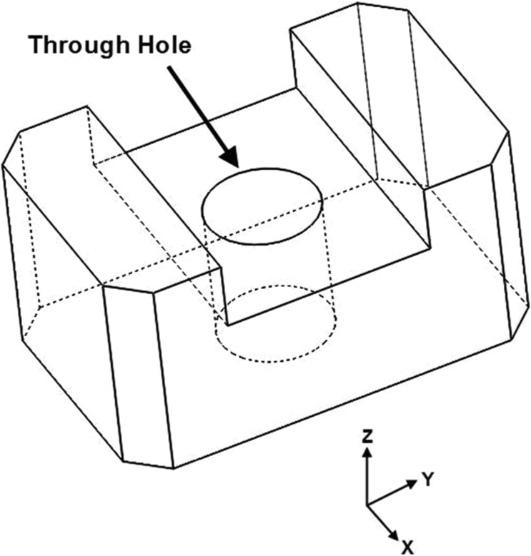
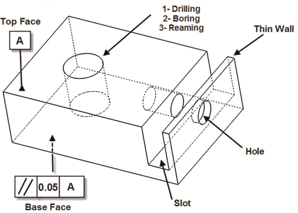
A feature precedence relationship determines the machining precedence of a machining feature by some constraints. The constraints such as tolerance requirement, the order of machining operations and good manufacturing practice determine the precedence among the machining features. For example, with respect to tolerance requirement, the top face is machined prior to the base face, as shown in Figure 2(a). Boring and reaming operation after drilling are necessary for machining of an accurate hole feature, as shown in Figure 2(b). Also as it is shown in Figure 2(c), good practice should include drilling the hole and then machining the slot to avoid deformation of the thin wall.
Dimensional and geometrical tolerances between features in precision manufacturing are mainly influenced on setup planning and fixture design. A correct dimensional control and inspection will be achieved when the workpiece locates on a drawing plane during machining. Otherwise, a tolerance stack up may be occurred. For preventing tolerance stack up, two concepts including “control faces” and “inferiority faces” are introduced in this article. The type of tolerance (dimensional or geometrical) and good manufacturing practice are effective in defining the control or inferiority faces. The definition of these two concepts is as follows:
Control face. Control face is a face that has considered as a datum. The precedence relation between features determines the control face. During geometrical tolerance relation, the reference face is a control face. However, in dimensional tolerance relation, considering this tolerance is between two external faces (case 1) or among an external and an internal face (case 2), and the definition of control face is different. In case 1, each of the one could be as a control face, for example, in Figure 3, the face
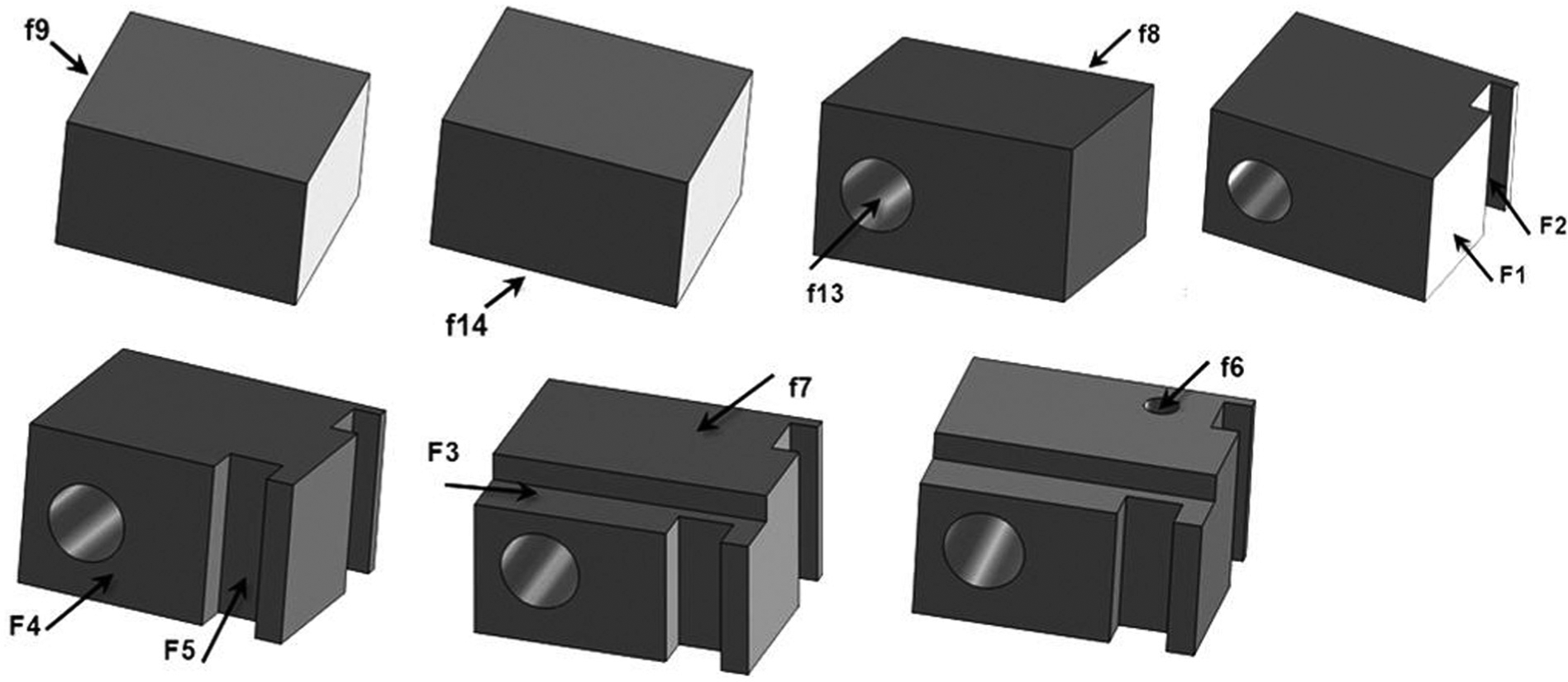
Inferiority face. A face that has to machine after another face with respect to economical and technological constraints is an inferiority face. According to the perpendicularity tolerance shown in Figure 3, the reference plane A has priority to the reference plane C. Therefore, the plane C is an inferiority face in this relation and has to be machined after the plane A.
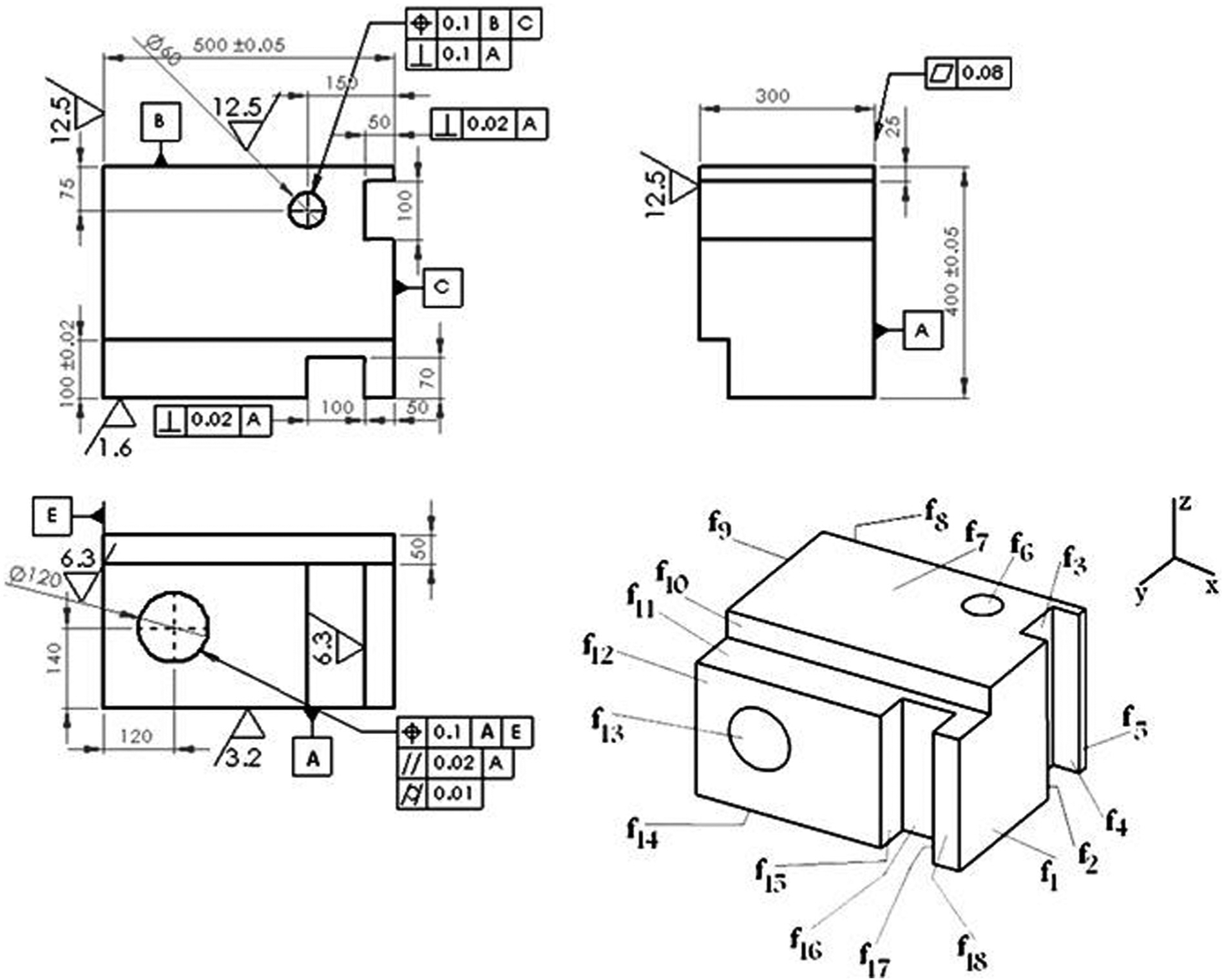
Drawings of a prismatic part. 17
After demonstrating preliminary concepts, the steps of heuristic algorithm will be explained in the next section.
Heuristic algorithm of setup planning
For executing this algorithm, three assumptions have to be considered as follows:
The workpiece machining process runs on a three-axis vertical milling machine.
All the operations of a feature are finished in one setup.
All the features of the part have to be machined.
Comprehensively, the steps of the algorithm are as follows:
Determine the inferiority and control faces for every feature.
Recognize multi-face features.
Sort the faces by attention to their corresponding inferiority faces. This sort is descending, and each face that has more inferiority faces is placed in higher rank. If the number of inferiority faces is equal, give priority to the face that its corresponding TAD sets have more features.
Select the level with highest priority for machining in the first step. If this face belongs to two or more TAD set, then neglect that.
Determine other features that are in the same TAD set with the selected face in the previous step.
In this step, several items have to be checked as follows:
Do all the selected features in previous step have a control face for machining?
Do they have the ability of replacement with their corresponding control faces?
Can we machine the features and their corresponding control faces in the same setup?
In an interface environment, the user should answer these questions. According to the user answer, two situations may occur, as follows:
If not, take the next priority in step 3.
If yes, the next step.
Are the control faces of the faces that have been considered for machining parallel with each other?
Like the previous step, two situations may occur, as follows:
If not, the next step.
If yes, then two tips should be applied.
The control faces of the face that has higher priority in the table in the same TAD are supposed as preliminary locating.
If the control faces of the next priority are not parallel with the control faces of the first priority, then this face should be machined in the present setup.
With respect to TAD, the first locating face will be selected. The first locating face is perpendicular to tool direction. In addition, the secondary reference plane is perpendicular to the first locating face, and the tertiary face is perpendicular to the first locating face and secondary reference face for locating method 3-2-1. If feature specifications do not offer any control faces for the secondary and tertiary datum faces, the larger face that is perpendicular to the first locating face will be selected as the secondary datum face, and the smaller face will be as tertiary datum face. Between two parallel faces for either secondary datum or tertiary datum face, the face has been machined so far has further priority. The flowchart of this algorithm has been shown in Figure 4.
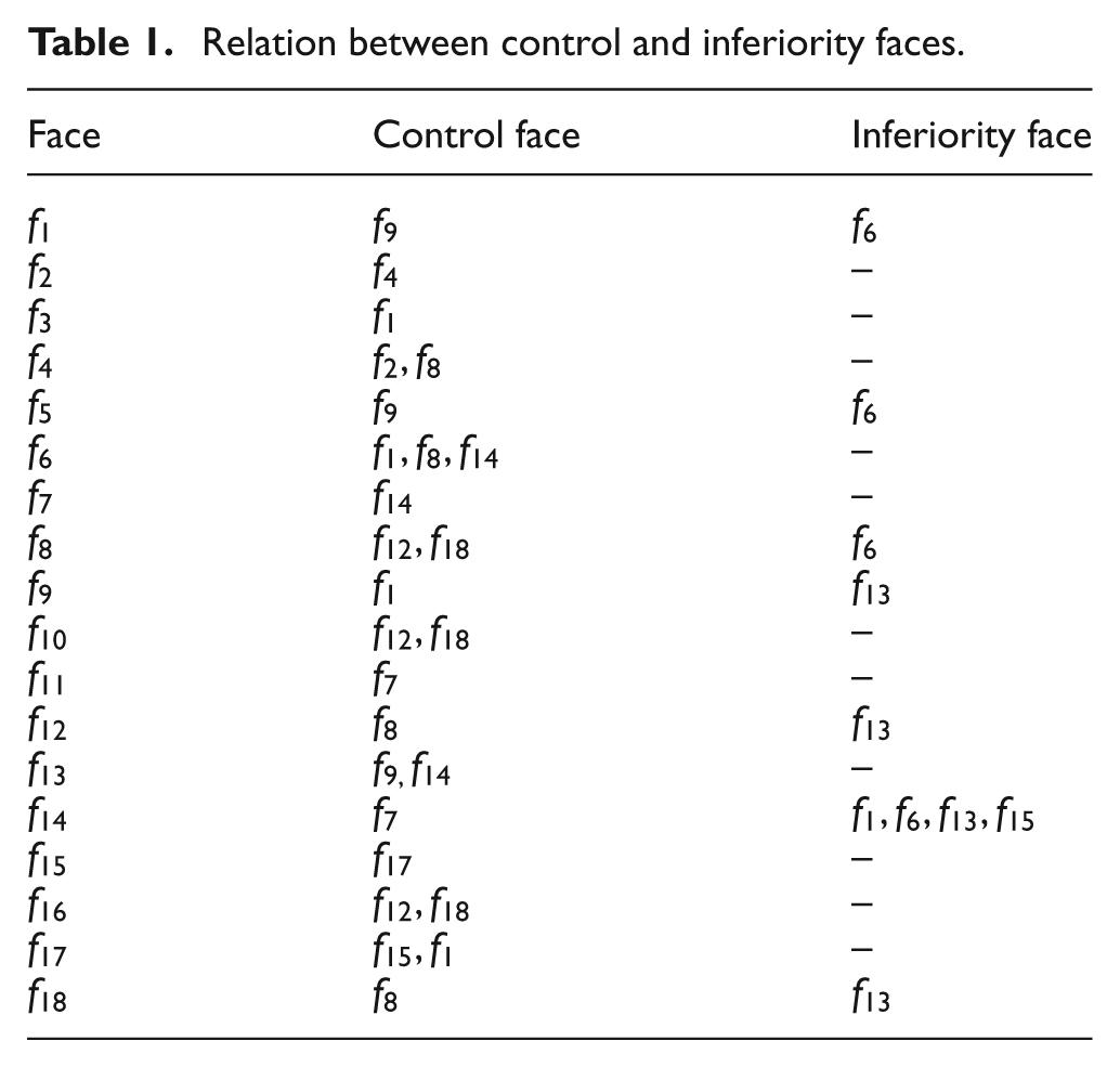
Relation between control and inferiority faces.
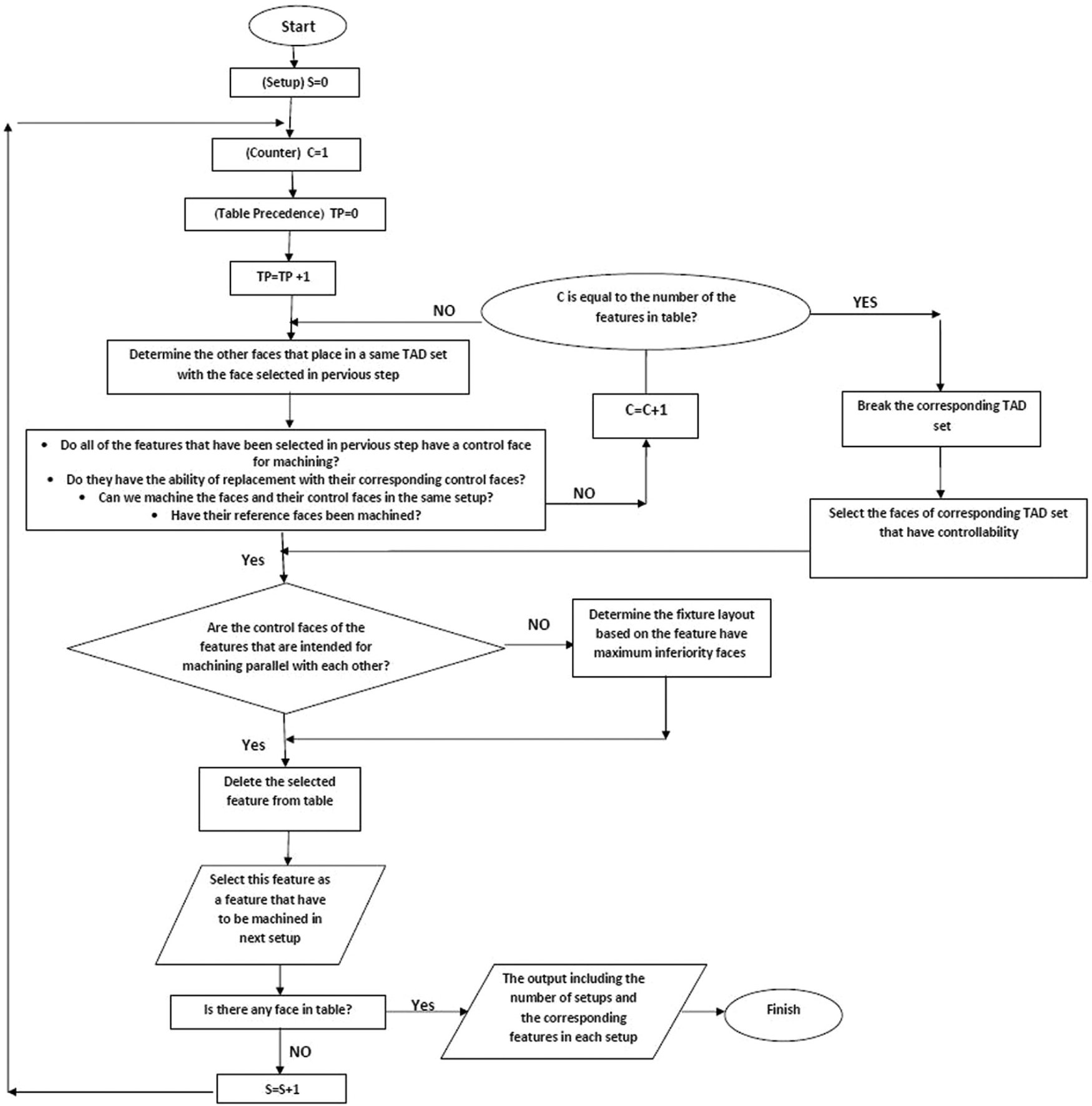
Flowchart of setup determination.
Illustrative example
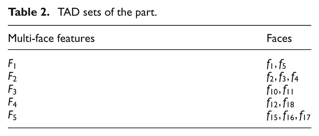
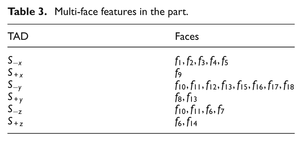
The prismatic part, as shown in Figure 3, is used to illustrate the setup planning algorithm. Table 1 illustrates the relation between control and inferiority faces. TAD sets for all the features of the part and five multi-face features in the part are shown in Tables 2 and 3, respectively.
TAD sets of the part.
Multi-face features in the part.
It should be noted that input to setup planning system is the part description. The information such as the control and inferiority faces (Table 1) and TAD sets (Table 2) are extracted from a user-interactive computer-aided design (CAD) system. A demo of system has been shown in Figure 5.
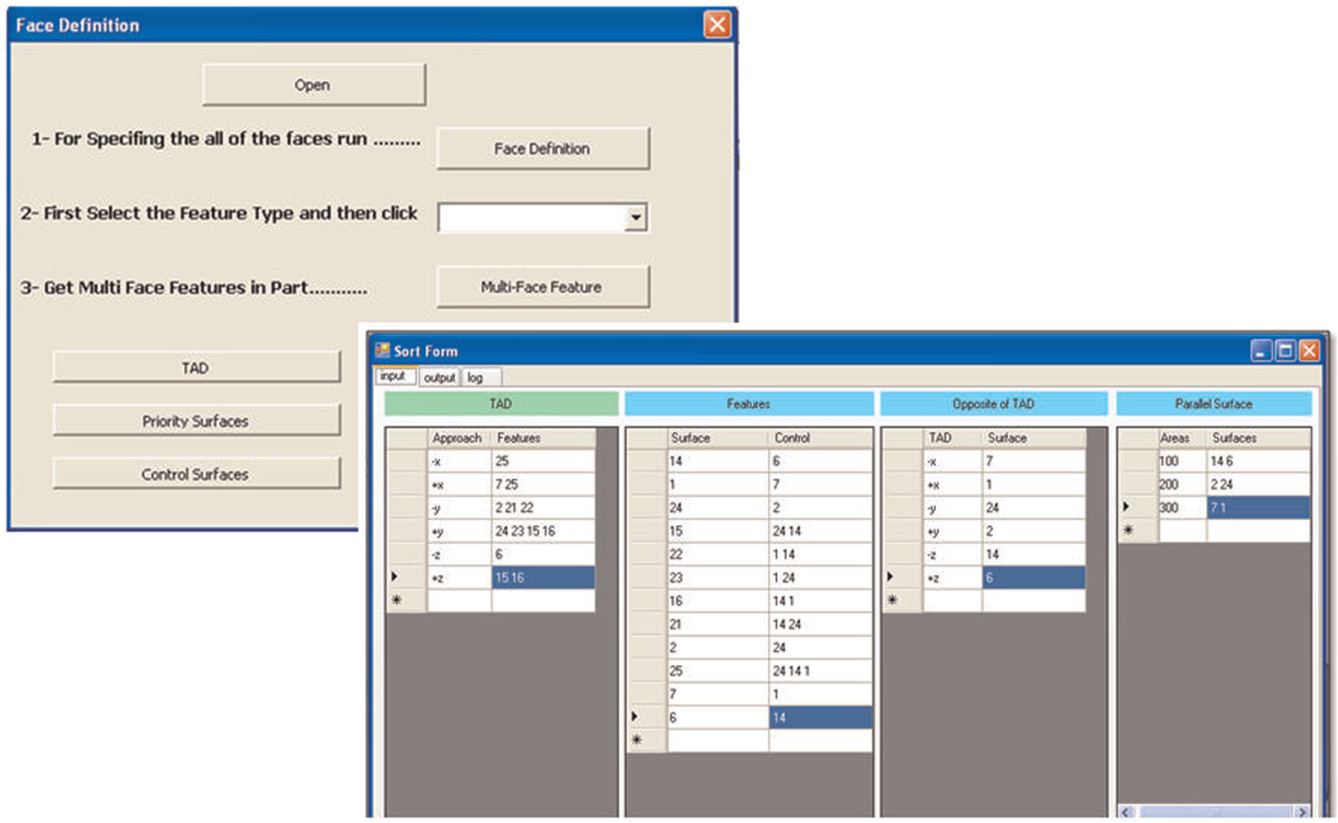
A demo of the system.
In the first step, the faces with maximum inferiority faces will be recognized. In fact, the first priority criterion in this algorithm is the faces that have the most inferior faces. With respect to Table 4, the
Prioritized the faces according to inferior faces.
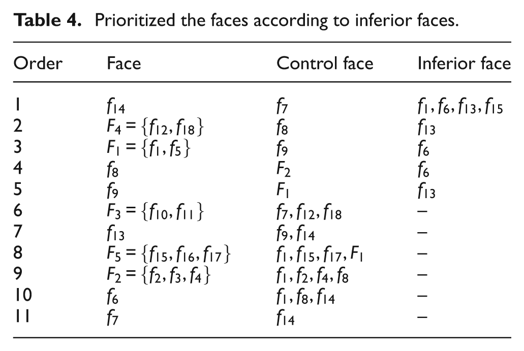
After omitting
Again, the first priority is
In the fifth setup, any of the features in remaining TAD groups could not machine; therefore, the algorithm broke the TAD set (
Faces that have not been machined until fifth setup are shown in Table 5 with respect to their control and inferiority faces. All of them belong to the same TAD set, and their control faces were machined or will machined on the same setup. Control faces for
Prioritized the faces according to inferior faces after fifth setup.
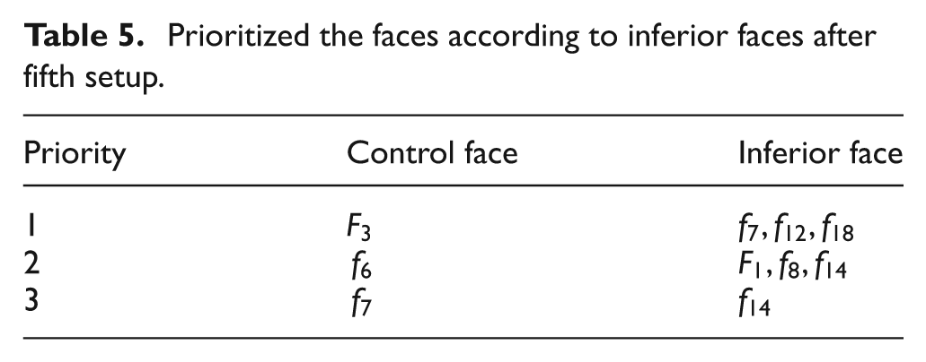
The first priority in the
Whole setup planning strategy and fixture design for the illustrated part.
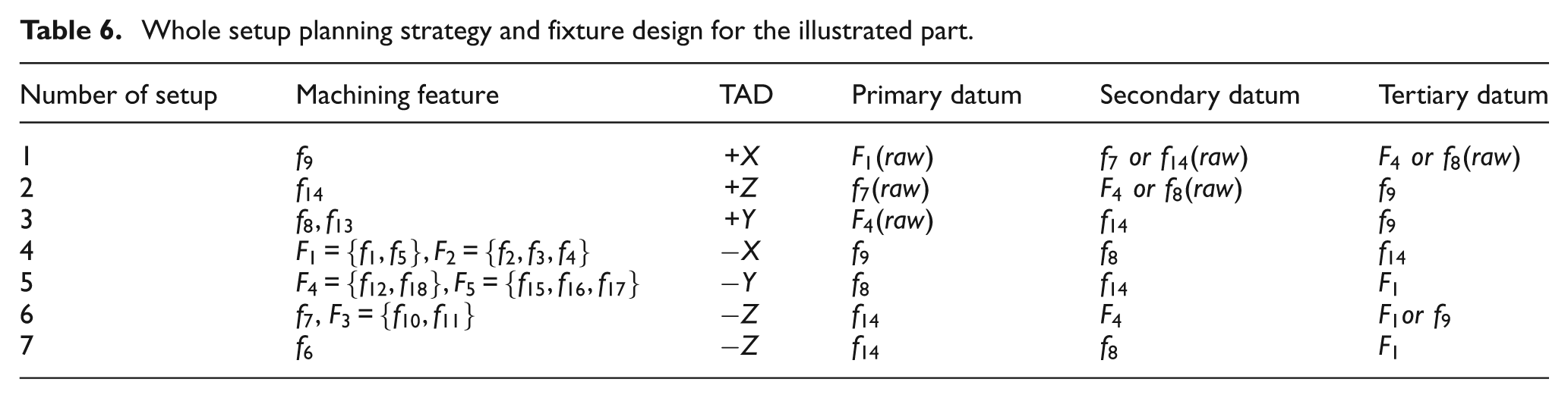
Machining steps.
Fixture planning
After developing the heuristic algorithm for setup planning, this article focuses on a mathematical model to investigate the height error of the locators in each setup. By attention to a need in the hole-making process, this model has been established. The main purpose of this model is to determine the effect of locator height error on hole position tolerance. Moreover, this model can be used for satisfying the other tolerance with some corrections.
Position tolerance
A position tolerance controls the position of a feature relative to one or more datums. For a hole, a position tolerance will control the position of the hole axis relative to specified datums, tilt of the axis of the hole and form deviations such as convexity or concavity of the axis. Figure 7 shows how the axis of a hole is controlled.
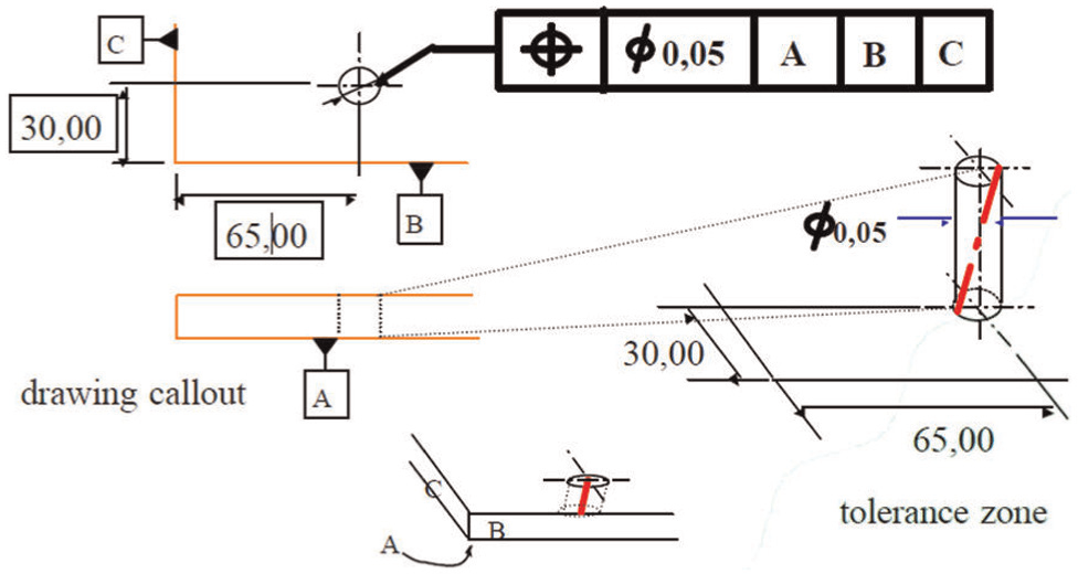
Illustration of a position tolerance.
Mathematical model
Fixture restricts the degrees of freedom (DOF) of the workpiece in space. Each workpiece in space has 6 DOFs. The DOFs can be restrained using six locators; each one restrains one DOF of the workpiece. A general 3-2-1 fixture layout shown in Figure 8 is a common method.
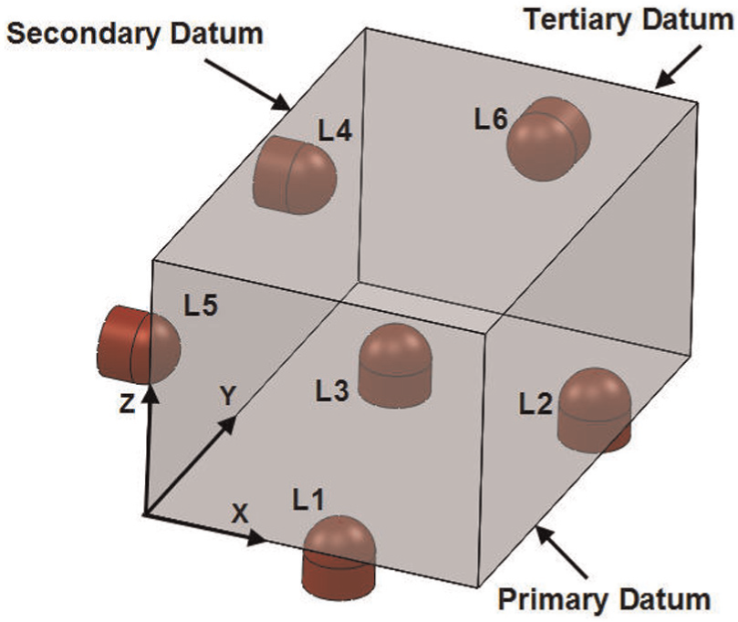
Configuration of datum planes and locators. 10
Any variation or error in locators’ layout will show itself as variation or error in the measurement of the distance between the feature and the datum. The hole position error is defined as the difference between the nominal hole position and the actual hole position. To get the actual hole position, the equation of the datum planes needs to be derived first in terms of the locators’ position. The primary datum plane is defined by three locators. Figure 9 shows the primary datum plane.
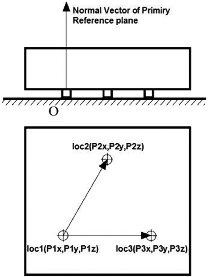
Primary datum plane.
The equation for calculating the primary datum plane is shown in equation (1)
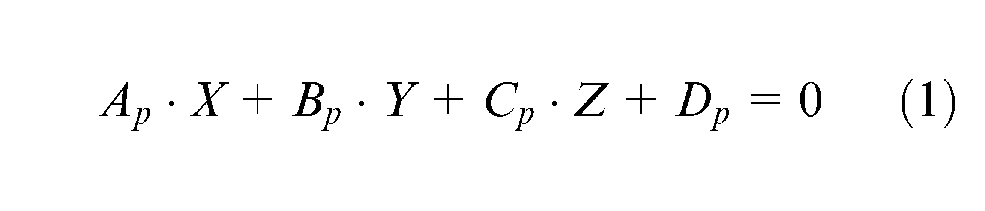
where
In these equations,

where
The tertiary datum plane is constructed with the position of sixth locator and two normal vectors on the primary and secondary datum planes. The required formula for obtaining the tertiary plane is shown in equation (3).
where
It is mentioned that the position error of the hole is the difference between the nominal hole position and the actual hole position. For example, in the part shown in Figure 10, the parameters of
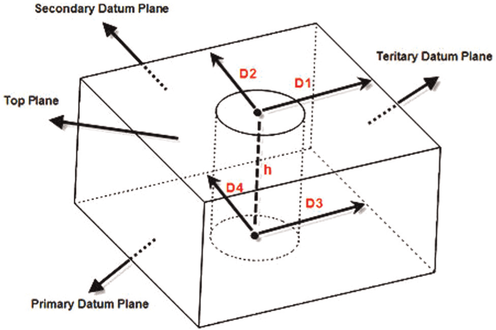
Position error at the top and bottom surfaces.
The actual position of the hole at bottom plane (primary datum) can be expressed by the following equations
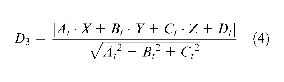
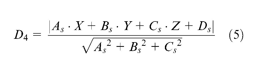
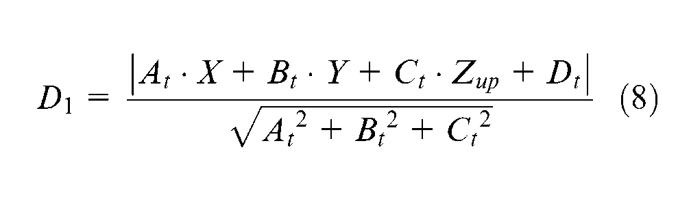
As shown in Figure 10, the distances of the actual position of the hole at top plane respect to the tertiary and secondary datum planes are
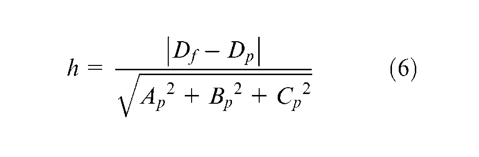
In the above equation, the Z coordinate of top plane is titled as

After obtaining the actual position of the hole at the top and bottom planes, the difference between the nominal and actual values (
If the
The above equations are very useful for studying the effect of locator height error on hole position tolerance. The equations are used to recognize whether a hole feature can be machined with the given locators’ errors successfully or not. These equations for each hole feature are solved by Maple software. The output of the model compares with the results of the simulation for validation test. For simulation, the “motion study” module in SolidWorks software is used. Although this module is a tool for investigating the motion and dynamics, it is also a powerful module for calculating the displacement of workpiece caused by fixture locator height error.
Case study
The seventh setup of the part shown in Figure 3 is used for evaluating the capability of this mathematical model. In this setup, a hole-making process is done in (−Z) direction, including one hole with a diameter of 60 mm. The value of locators’ position and their corresponding height error are presented in Table 7.
Position and height errors of locators.
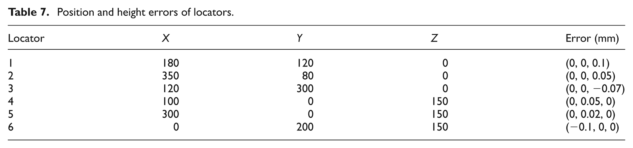
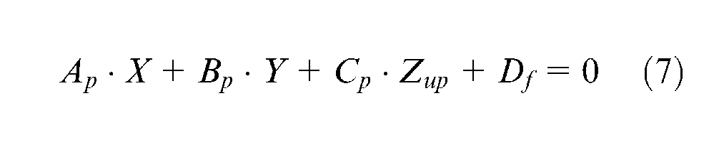
The drilling tool should go on point (105, 75) and drilling cycle run in −Z direction. In this situation, the tool path vector intersects the primary datum plan and top surface, while these planes are parallel in theory. The primary datum plane can be obtained by substituting the locator position value in equation (1) as follows
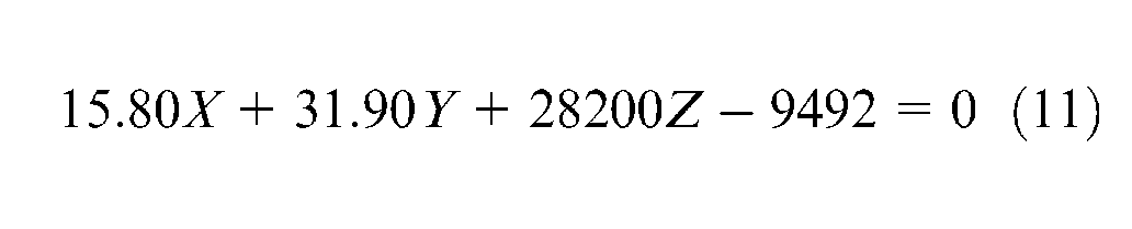
Let X = 150 and Y = 75, the Z value will be equal to 0.1677. This value is the height of intersection in bottom surface. Similarly, the equation of the top surface will be taken using equation (7). The height of intersection of tool path and top surface (
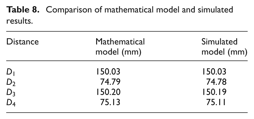
With respect to Figure 10, the position tolerance can be satisfied while the amounts of
Comparison of mathematical model and simulated results.
Conclusion
This research deals with the problems of setup and fixture planning for machining of prismatic parts. In the first section, a new heuristic method is presented to plan the setups with accurate respect to datum faces in design and manufacturing. For preventing tolerance stack up, we tried to use the datum face as a reference plane in setup planning. Two concepts, namely, “inferiority face” and “control face,” have been used for this purpose. In the next section, a new mathematical approach is presented to determine relationship among misplacement of the locators and dimensional specifications of the workpiece by linear algebra concepts. In this model, the planes of workpiece actual coordinate system (ACS) are mathematically modeled in the workpiece theoretical coordinate system (TCS). This model is useful for recognizing the relation between locator error space and workpiece error space. The main purpose of developing the model is to determine the effect of locator height error on hole position tolerance. This approach is very useful in the hole-making process. The capability of this model is verified by simulation in “motion study” module in SolidWorks software. The system is developed in Visual Basic on a SolidWorks platform. The effectiveness of this model is studied by an industrial component. Furthermore, using this method, the cost and time-consuming fixture design reduce considerably. In ongoing research, the effect of position error will be developed in the current model. The present mathematical model is used to study the effect of locator position by implementing an optimization method based on the GA approach.
Footnotes
Declaration of conflicting interests
The authors declare that there is no conflict of interest.
Funding
This research received no specific grant from any funding agency in the public, commercial or not-for-profit sectors.