
Abstract
Microgrooving on crystalline germanium (Ge) <100> surface using 1064 nm wavelength ultrafast laser pulses under ambient condition is investigated. The interaction of laser and target material and the influence of processing parameters such as laser power, pulse repetition rate and scan speed on the groove dimensions and surface roughness are studied. For the laser radiation fluence range used (0.4–0.8 J/cm2), material removal is primarily controlled by optical penetration depth. The depth and width of grooves increase with laser power. In multipulse irradiation, heat accumulation due to residual thermal energy from successive laser pulses results in a greater material removal. Furthermore, groove depth and width decrease as the pulse repetition rate increases from 0.5 to 2 MHz, due to the decrease in pulse energy with an increase in repetition rate causing ablation threshold fluence to move towards the central portion of the Gaussian pulse. Surface roughness has not shown significant changes for the parameters used in this study. A micro-Raman analysis of groove surfaces reveals a change in the crystallinity of the Ge due to laser irradiation.
Introduction
Ultrafast (or ultrashort pulsed) lasers have attracted a lot of interest for the fabrication of precise microstructures with good accuracy and reproducibility. It has distinct advantages over the conventional machining techniques in processing materials ranging from metals to semiconductors, ceramics and polymers directly without any further processing. This technology has enormous flexibility by presenting various parameters to control the dimensions, surface roughness and crystallinity of machined structures. The parameters include laser radiation fluence, pulse repetition rate, pulse width and scan speed. Among the types of microstructures that can be manufactured using laser micromachining technique, microgroove is an important structure for various microdevice applications. The short interaction time and high peak power lead ultrafast laser interaction process with lesser heat diffusion and, consequently, smaller heat-affected zone (HAZ). 1 In metals, the absorption of energy from laser pulses is characterized by inverse bremsstrahlung, whereas in semiconductors and dielectrics, free electrons are generated by avalanche and multiphoton ionization. 2 Recently, the micromachining of semiconductor materials such as silicon (Si), Ge and gallium arsenide (GaAs) using ultrafast laser pulses has attracted growing attention owing to the possible applications in microelectronics and microelectromechanical systems (MEMS).3,4 For the efficient use of this technology to generate the required microstructures in such applications, it is essential to understand the dependence of process parameters.
Some important studies have been conducted in the fabrication of micro/nanostructures on Si using high-repetition rate ultrafast lasers with single and multiple passes.5–8 However, investigations pertaining to micromachining aspects of crystalline Ge using ultrafast laser pulses are limited. Nevertheless, some studies have devoted to investigating laser interaction mechanisms with crystalline/amorphous Ge thin films and bulk. The transient behaviour of plasma produced in Ge surface irradiated with picosecond pulses (5–10 ps) of 1064 nm wavelength was reported.9,10 The irradiation generates electron densities in the order of 2 × 10 20 cm−3. It is evidenced from the studies that the structure of conduction band, phonons and plasmons plays a vital role in the temporal evolution of plasma. In addition, ultrafast X-ray diffraction technique was used to show energy transport and heating mechanisms during laser processing of crystalline Ge <111>. 11 The Ge samples were processed using 800 nm wavelength femtosecond laser pulses of fluence of 0.05 and 0.1 J/cm2, with the number of pulses ranging from 50 to 500. The results have revealed that the dependence of melting and ablation thresholds on laser pulse width is essentially determined by nonlinear optical absorption, high-density carrier diffusion and delayed Auger heating. Moreover, phase transformation during irradiation depends on non-equilibrium heat diffusion during thermalization.
Studies have been reported on nanostructuring of crystalline Ge using 810 nm wavelength, 210 fs laser pulses with radiation fluence ranging from 0.7 to 51 J/cm2.12,13 The processed area contains microstructures on which nano-sized particles are attached. Micro-Raman analysis of processed area reveals peak shifts of bands accompanied by asymmetric broadening due to phonon confinement and correlated to particle size. With regard to material removal, two types of semi-logarithmic relationships between single pulse ablation depth and laser radiation fluence were discussed.12,13 For radiation fluence of <8 J/cm2, ablation is determined by optical penetration depth, while for greater fluences the region is characterized by electronic heating depth. Nano-spiked microstructures were generated on crystalline Ge surface processed using the same process parameters in a sulphur hexafluoride (SF6) environment. 14 It has been found that higher radiation fluence with less number of pulses favours the formation of nano-spikes. As the fluence increased, conical microstructures transformed into tall straight-walled pillar-like structures and the nano-spikes disappeared. Furthermore, the surface orientation of Ge crystal exhibits a higher tendency for conical structure formation in vacuum (less than 100 mTorr) under multipulse irradiation. 15 Processing of amorphous Ge thin films generates various crystallization regimes in the form of nanospheres. 3 On the other hand, the processing of crystalline Ge led to the generation of polycrystallites.16,17 The fabrication of high-frequency periodic surface structures in Si and Ge surfaces by nano joule femtosecond laser pulses at high repetition rates in air was reported. 18 Various mechanisms have been discussed including the interference of diffracted waves from the surface with incident beam. 19 Hence, ultrafast laser micromachining is an efficient technique for the fabrication of nano/microstructures, but further studies are essential to understand the process so as to control the micromachining process and the machined structures.
In this study, microgrooving on crystalline Ge using ultrafast laser pulses under ambient condition is presented. The interaction of laser and target material and the influence of laser power, pulse repetition rate and scan speed on the groove depth and width, phase transformation and machined surface roughness will be evaluated. The laser–material interaction mechanisms responsible for the changes in Ge microstructures as a function of process parameters will also be discussed. The micro-Raman spectroscopy technique is used to analyse the properties of the machined surfaces.
Experimental work
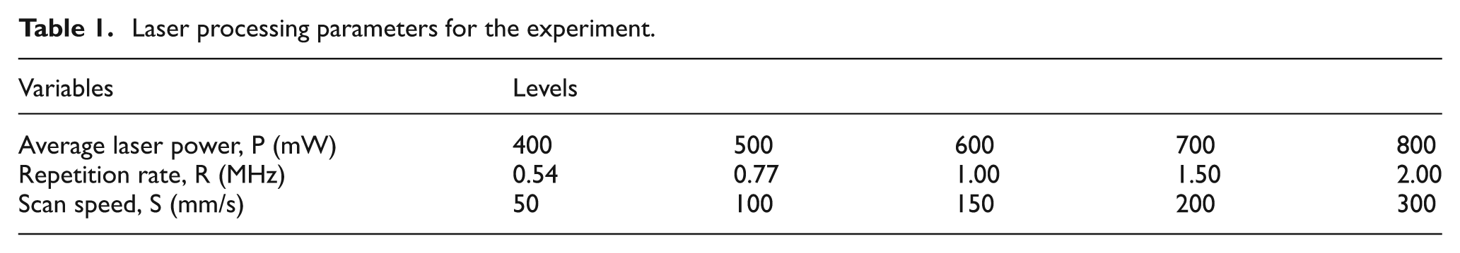
A femtosecond fibre laser system with a wavelength of 1064 nm and an average power of 3.2 W capable of delivering pulses at the duration between 200 fs and 2.8 ps was used in this study. The pulse repetition rate could be varied between 0.5 and 2 MHz. In this system, the average laser power varies with laser pulse duration at a constant repetition rate. In order to vary output power at a constant pulse width, an attenuator unit comprising a λ/2 plate and a polarizer was used. The laser beam was linearly polarized and beam diameter from the system was 1.4 mm. A beam expander was used to increase beam diameter from 1.4 to 11.2 mm. A lens of focal length 100 mm was used to precisely focus the beam on the work surface. The energy distribution of laser beam was nearly Gaussian, and estimated spot diameter was 15.7 µm. A Newport X–Y translation stage was used to move the sample at the scan speed varying from 50 to 300 mm/s. The process parameters used for machining Ge are shown in Table 1. The pulse widths correspond to pulse repetition rates of 0.5, 0.77, 1, 1.54 and 2 MHz are 200, 500, 1600, 2000 and 2800 fs, respectively. The three process parameters considered in this experiment were average laser power, pulse repetition rate and translation or scan speed of sample. Each of these parameters was selected at five levels for a full factorial design of experiment. A schematic of the grooving procedure is illustrated in Figure 1(a). The energy per pulse for different average powers and pulse repetition rates used in the present experiment is shown in Figure 1(b). The pulse energy decreases significantly at higher repetition rates. For instance, a pulse at the energy of 1.6 µJ at 0.5 MHz pulse repetition rate reduces to 0.3 µJ at 2 MHz at the laser power of 800 mW. The maximum pulse energy was available for 0.5 MHz only.
Laser processing parameters for the experiment.
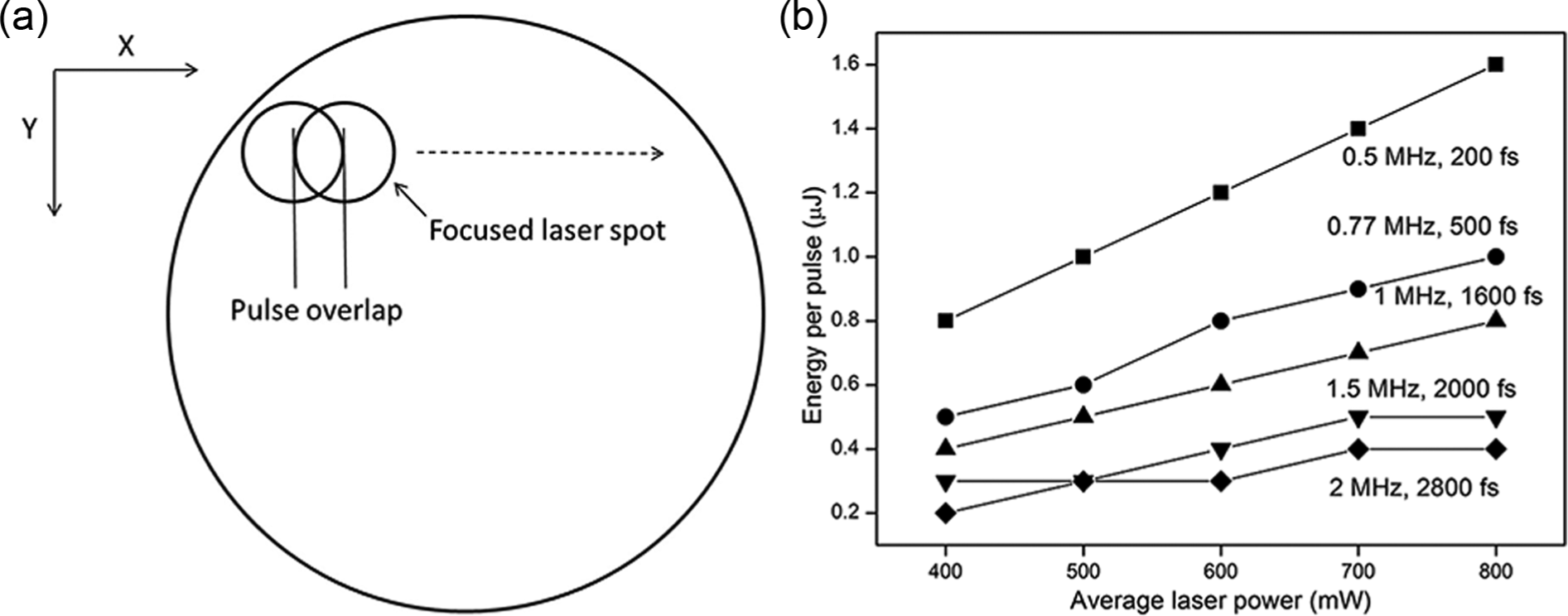
(a) Schematic representation of laser grooving of Ge and (b) laser pulse energy as a function of the average laser power for different repetition rates.
The samples used were crystalline Ge at <100> orientation with the thickness of 487 µm and 25 mm in diameter. The surface polished to the nanometre scale was used for laser irradiation. To study the influence of process parameters, grooves were machined on sample surface by single pass. The grooves were analysed using a KEYENCE colour three-dimensional (3D) laser scanning microscope (Model VK-X200). The groove depth, width and surface roughness were measured at five different locations along each groove and the average was taken. Raman spectroscopy analysis of the samples was carried out at room temperature with 514.5 nm line of an Ar-ion laser excitation (Renishaw inVia Raman Microscope). The laser beam was focussed on the sample surface with a spot size of 0.5 µm.
Results and discussion
Ultrafast laser–material interaction
Studies have shown that crystalline Si, Ge and GaAs exhibit non-thermal melting upon irradiation with ultrafast laser pulses, while thermal melting occurs at laser pulses of longer timescales.3,11 The width of ultrafast laser pulses distinguishes its interaction process with materials from other long laser pulses in aspects like absorption, energy transfer to lattice, heating, vaporization and plasma formation. 20 The energy absorption from laser pulses is determined by the energy of photons and band structure of Ge. The wavelength of laser radiation used in this study was 1064 nm and the corresponding photon energy was 1.17 eV, which was greater than the band gap energy of Ge (0.67 eV). Upon irradiation of the sample, photons are absorbed primarily by valance band electrons, thus generating a dense population of electrons and holes in conduction and valance bands, respectively. In addition, higher laser intensities could generate larger electron densities through single photon or multiple photons and the electron–electron impact ionization processes. The absorbed energy in the electronic system is subsequently transferred to lattice. In the case of ultrafast laser pulses, energy deposition with electrons is faster than the electron–phonon interaction process, which is of the order of few tens of picoseconds. The timescales of lattice heating in the course of laser irradiation are essential for the understanding of Ge ablation. Furthermore, the processes that control lattice heating dynamics are Auger heating, 21 two-photon absorption 22 and high-density carrier diffusion. 23 According to these studies, the high density of electron–hole pairs can result in lattice instability (disordering of atoms) within a timescale of ≤100 fs. During this period, the lattice remains nearly ‘cold’, a process that is called ‘cold’ or ‘nonthermal’ melting. Once energy from electrons is transferred to the lattice by electron–phonon interaction, non-thermal melting ends and a hot liquid develops. When laser is removed, the rate of energy deposition to lattice drops sharply and thermal properties of material decide the cooling rate that lasts up to several hundred nanoseconds. Therefore, the modelling of ultrafast laser–material interaction is possible only if electron and lattice temperatures are taken into account. During multipulse laser irradiation, although a major portion of incident energy is spent through processes like bond breaking and multiphoton ionization, a fraction of it is used for heating, which remains in the irradiated region and diffuses into the material bulk. Consequently, heat accumulates in and around the focal volume and results in a substantial increase of temperature. At higher pulse repetition rates, the time between laser pulses is less than heat diffusion time and, hence, results in a larger heat accumulation. Recent studies reveal an overall enhancement of residual thermal coupling of samples irradiated with multipulse femtosecond lasers under ambient condition. 24 Furthermore, increasing surface temperature of Ge reduces the band gap substantially and results in an enhancement of the absorption coefficient. Thus, a significant reduction in the deposition depth of laser pulse energy takes place, which contributes to nonlinear heating as well as the heat transport process.
Since material removal rate is related to energy absorption from laser pulses by the target material, the knowledge of parameters responsible for the timescale of material heating is essential for material ablation. In terms of microgroove fabrication, the timescales of the processes are determined by the number of laser pulses, which in turn is controlled by the scan speed of the laser. Accordingly, scan speed can be expressed in terms of the effective number of pulses delivered to the sample. In other words, the surface is exposed to multiple laser pulses while being continuously translated with various scan speeds. In order to fabricate grooves with little debris, smooth surface and less HAZ, the number of pulses and their overlap for a specified scan speed are important. For grooves machined with a single pass, the effective number of pulses received by the sample surface can be estimated from

where N is the effective number of pulses within a laser spot, ωo is the radius of laser spot, f is the pulse repetition rate and V is the scan speed. The effective number of pulses as a function of scan speed for different pulse repetition rates is depicted in Figure 2(a). For a given repetition rate, the effective number of pulses decreases with an increase in scan speed. On the other hand, it increases with repetition rate at a constant scan speed. The pulse-to-pulse overlap on the sample surface is defined by equation 1 − (1/N) and is approximately equal to 0.98 for the repetition rates and scan speeds used in the present experiment. This means that laser pulses at the irradiated spot are almost fully overlapped for the given scan speed. During micromachining with laser pulses of high repetition rate (>100 kHz), pulse separation time is less than the heat diffusion time, resulting in an accumulation of heat in the focal volume. If the pulse energy is sufficient, material at the focus will melt and as more laser pulses are absorbed, melted volume will increase. When laser is removed, melt rapidly cools into a structure with altered material properties. Besides, morphological changes of groove surfaces are dominated by cumulative heating, melting and cooling dynamics of material. Since laser beam is scanned over sample surface, the size of melted volume can be controlled by the effective number of laser pulses applied. A combination of high pulse repetition rate and fast heat accumulation offers high material removal rates with benefits of very low HAZ due to the decreased thermal cycling.
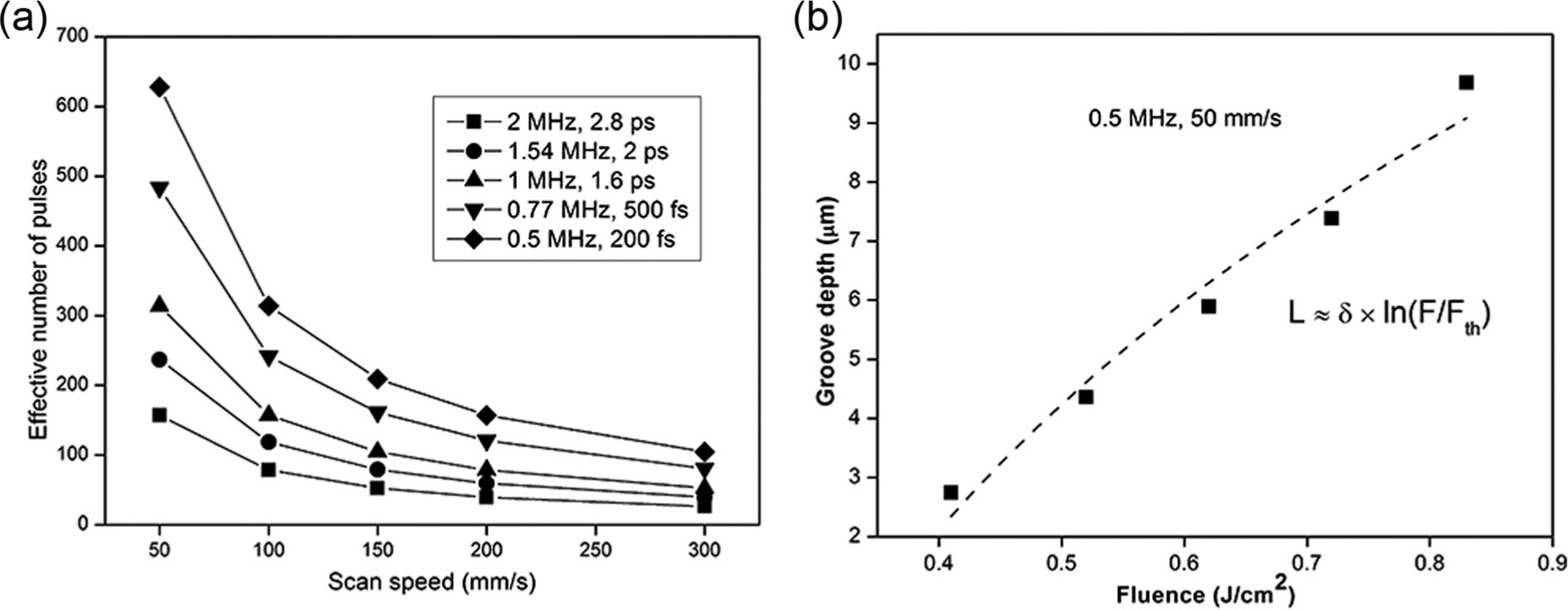
(a) Effective number of laser pulses as a function of scan speed and (b) groove depth as a function of laser fluence (where the dashed curve was fitted in logarithmic form from the experimental data, and the symbols are for experimental data).
Figure 2(b) shows the experimental groove depth on crystalline Ge as a function of the radiation fluence at the 0.5 MHz pulse repetition rate and a scan speed of 50 mm/s. Although the effective number of pulses N is constant for a given scan speed, groove depth exhibits a semi-logarithmic dependence on the radiation fluence, as shown by the dashed line in Figure 2(b). It is evidenced from the literature that for the radiation fluence used in the present experiment, material removal is mainly influenced by optical penetration depth.16,25 The ablation depth L can be described by
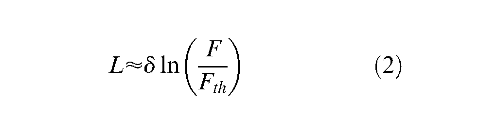
where δ is the optical penetration depth, F is radiation fluence and Fth is the ablation threshold fluence. A fitted line to the experimental data is shown in Figure 2(b), which gives an estimation for Fth = 0.32 ± 0.02 J/cm2 and δ = 9.67 ± 0.9 µm. The ablation threshold fluence estimated with the data at 200 mm/s was also made, which has the same trend. The minor discrepancy observed between the experimental groove depths from the semi-logarithmic curve can be explained in terms of higher order optical nonlinearity with multipulse irradiation. Furthermore, with multipulse processing, sample surface undergoes chemical and structural changes after the first few pulses, which makes a less accurate comparison with initial properties of sample.24,26 When laser ablation is mainly governed by optical penetration depth, the localized energy heats a thin layer of the sample and quickly changes it from a liquid to vapour phase status. Consequently, better machined structures can be obtained due to reduced thermal effects.
Effect of laser power, scan speed and pulse repetition rate on groove depth and profile
Figure 3 shows the typical relationship between the groove depth and laser power under different pulse repetition rates (or pulse widths). The effective numbers of laser pulses estimated for 50 and 200 mm/s are 39 and 157, respectively. At a constant pulse repetition rate, groove depth increases with an increase in the average laser power. Since the scan speed and repetition rate are held constant, the number of pulses remains the same for different average laser powers. However, pulse energy increases with laser power, as shown in Figure 1(b), and as a result, more energy is deposited into the material as the laser power increases. This leads to an increase in melting and material removal, and hence, groove depth increases. On the other hand, pulse energy decreases with an increase in the repetition rate when the laser power is held constant, which results a decrease in groove depth. Moreover, when the scan speed increases from 50 to 200 mm/s, a significant reduction in groove depth is witnessed. This could be explained with a decrease in the number of laser pulses in the irradiated spot.
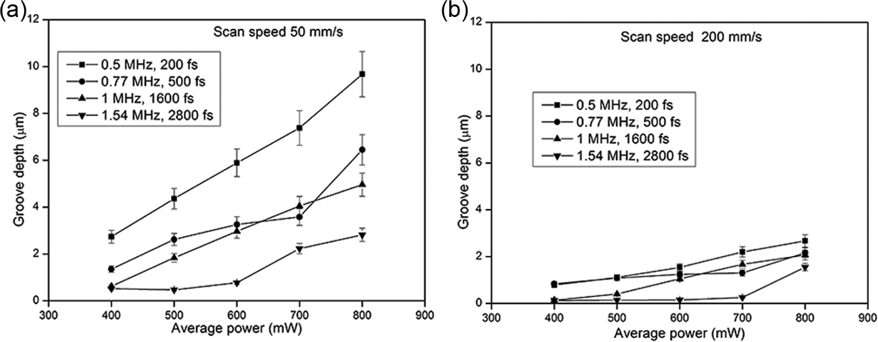
Effect of average laser power and pulse repetition rate on groove depth. (a) Scan speed 50 mm/s, (b) scan speed 200 mm/s.
The microgrooving performance can be indicated by the geometrical characteristics (profile) and accuracy of grooves. Representative laser scanning microscopy images illustrating the surface of grooves machined and their corresponding cross-sectional profiles are presented in Figures 4 and 5. At 0.5 MHz and 50 mm/s, although the groove depth increases with laser power (see Figure 3a), it is accompanied by an increased amount of debris and redeposition of ablated material in the vicinity, as shown in Figure 4(a). Since the number of pulses striking on a given target area increases as the scan speed decreases, melting also increases due to cumulative heating. The molten material from the bottom of groove is accelerated by vapour pressure to side and forms a resolidified ridge-like structure at the edge of groove, as illustrated in Figure 4(b). These effects are significantly reduced with grooves machined at low power and also with higher scan speed (Figure 5(a)), but at the cost of groove depth.
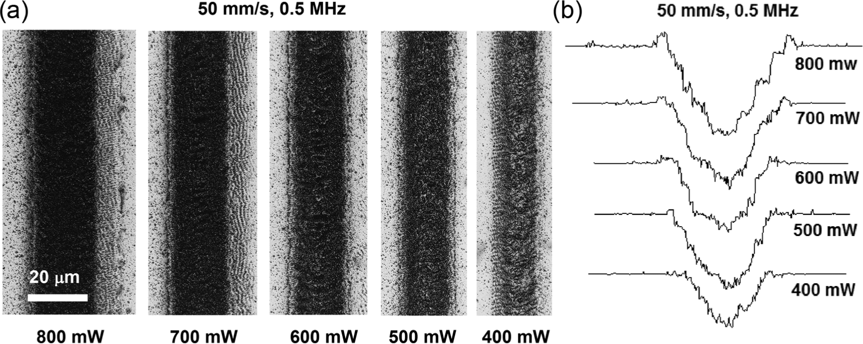
(a) Laser scanning microscopy images of grooves machined with radiation fluence between 400 and 800 mW at 50 mm/s scan speed and 0.5 MHz pulse repetition rate and (b) profiles of the machined grooves.
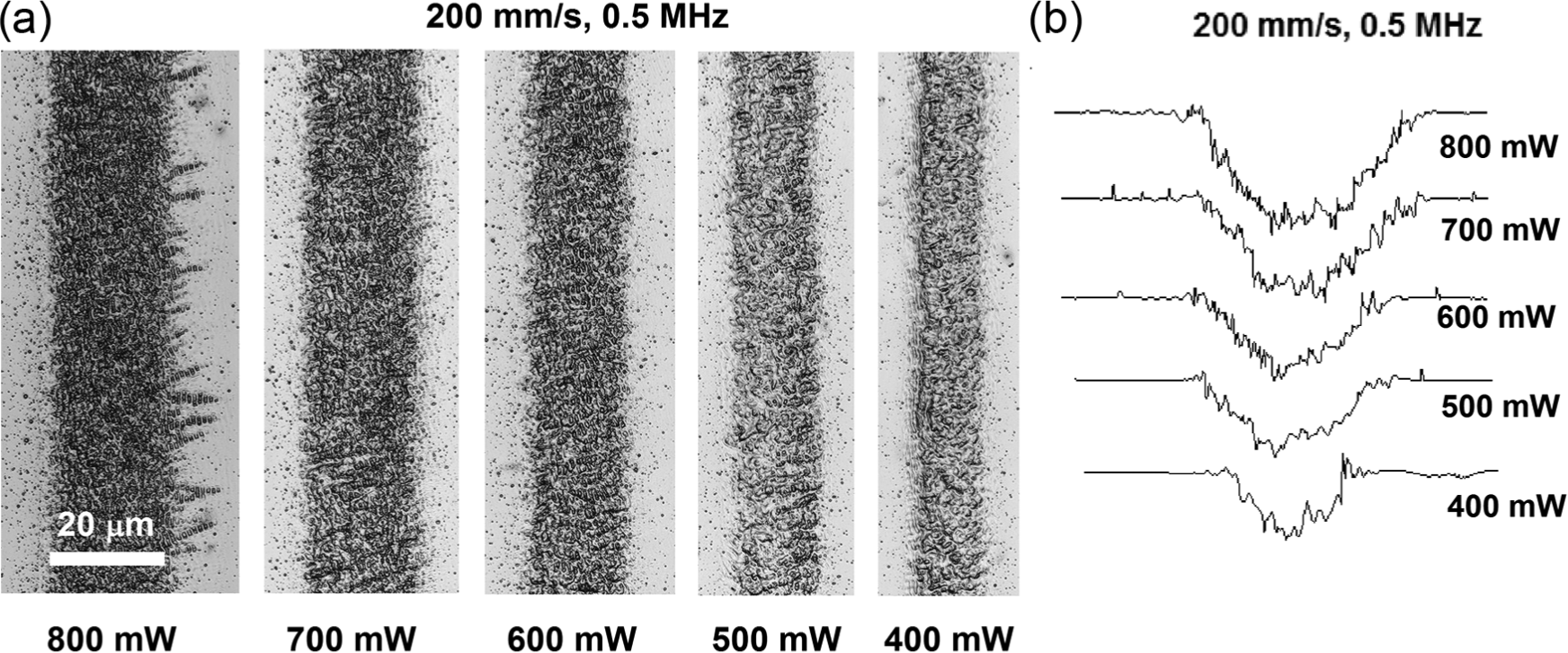
(a) Laser scanning microscopy images of grooves machined with radiation fluence between 400 and 800 mW at 200 mm/s scan speed and 0.5 MHz pulse repetition rate and (b) profiles of the machined grooves.
The cross-sectional profiles of grooves machined with the scan speeds of 50 and 200 mm/s are significantly different from each other. The profile is more V-shaped at lower scan speeds such as 50 mm/s, but somewhat U-shaped for grooves machined at higher scan speeds such as 200 mm/s. At a low scan speed, radiation fluence at the bottom of the groove decreases as the depth increases, and consequently, melting and material removal decrease. Therefore, the profile of grooves appears V-shaped, as shown in Figure 4(b). This effect is less pronounced at higher scan speeds, and hence, the profile of groove appears U-shaped, as shown in Figure 5(b). Thus, by controlling the scan speed, the groove cross-sectional profile can be controlled to a desired shape. Industrial use of ultrafast pulse laser micromachining is often limited by the average laser power, which results in low processing speed and throughput. This could be enhanced by increasing pulse repetition rate. However, a high pulse repetition rate can result in an interaction of ablated particles with subsequent laser pulses. In Figure 6, the groove depth is plotted as a function of the repetition rates for laser power at 500 and 800 mW. For a constant scan speed, the depth of groove decreases with pulse repetition rate. In addition, the change in groove depth with the repetition rate appears to be more significant at the 50 mm/s scan speed. This could be due to the increased number of laser pulses at a given target spot.
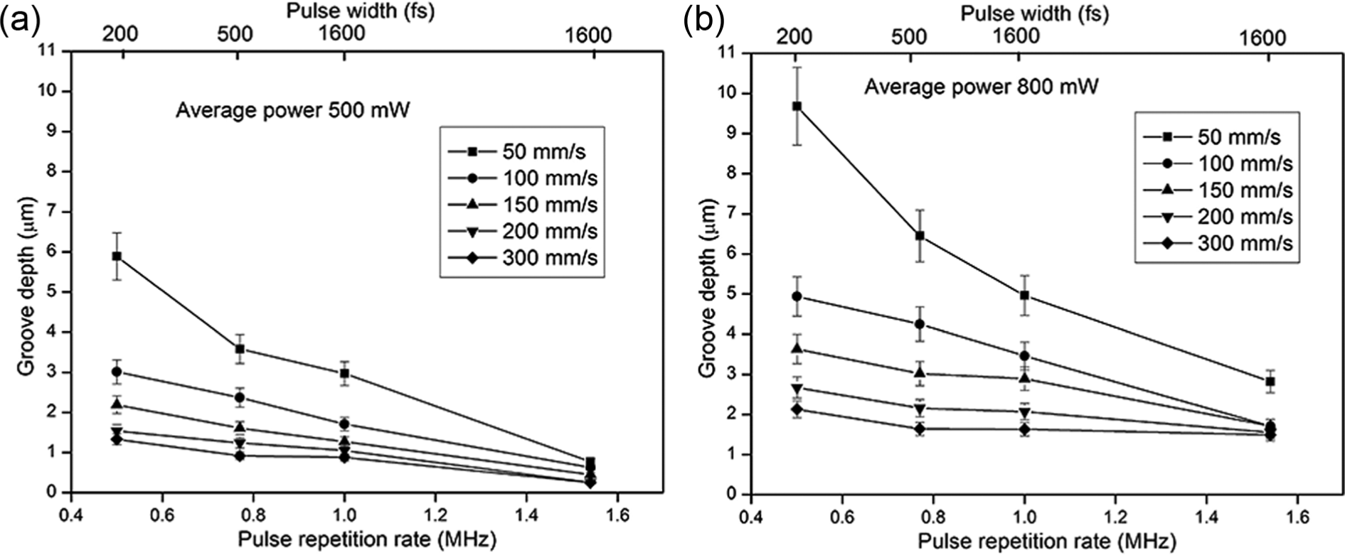
Effect of laser pulse repetition rate and scan speed on groove depth. (a) Average power 500 mW, (b) average power 800 mW.
Effect of laser power, repetition rate and scan speed on groove width and surface roughness
In this study, the measurement of groove width was taken at the groove top, so it is in fact referred to groove top width. In laser machining, groove width is essentially determined by the laser beam spot size. Nevertheless, the spatial intensity distribution of the beam power and material ablation threshold fluence are also important factors in affecting groove width. Figure 7 shows the groove width as a function of laser power under different pulse repetition rates. It can be seen that the groove width increases with laser power for a constant pulse repetition rate; it also increases very marginally with scan speed. The large fluctuation in the groove width at 1.54 MHz (Figure 7(b)) with respect to the average power could be due to the variation of pulse energy and width of the laser pulse (2 ps) at this repetition rate or by experimental errors.
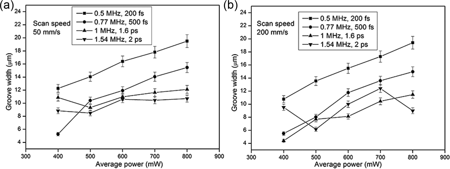
Effect of average laser power and pulse repetition rate on groove width. (a) Scan speed 50 mm/s, (b) scan speed 200 mm/s
The variation in laser pulse energy with the average laser power alters the radiation fluence on the target surface. Since laser beam profile is nearly Gaussian as depicted in Figure 8, radiation fluence is maximal at the beam centre line and decreases radially outwards in the form of
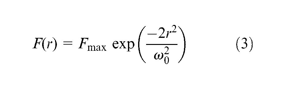
where r is radial distance from beam centre line, ω0 is beam radius and Fmax is maximum fluence at r = 0. The distance at which fluence decreases to 1/e 2 is the beam radius. For instance, the maximum radiation fluence is indicated as F1,max at a constant repetition rate (Figure 8). Radiation fluence above the ablation threshold is over a specified area on the irradiated spot. Material removal occurs over this area on the sample surface. Since the laser beam scans the sample surface, the width is determined by the overlapping of laser pulses having radiation fluence above the ablation threshold over the specified area. As pulse repetition rate increases, pulse energy gradually decreases and the area over which radiation fluence is above ablation threshold is reduced. This is illustrated with the peak radiation fluence F2,max in Figure 8 for a low-energy laser pulse. Consequently, the material removal area is reduced, which in turn decreases the groove width. When the surface is irradiated with multiple laser pulses, the increased absorption of irradiated surface reduces the ablation threshold (incubation effect) due to the accumulation of damage or defects from individual laser pulses. This is another important effect in determining morphology and dimensions of groove. In general, groove dimensions are essentially controlled by laser radiation fluence and the effective number of pulses 27 on the irradiated spot.
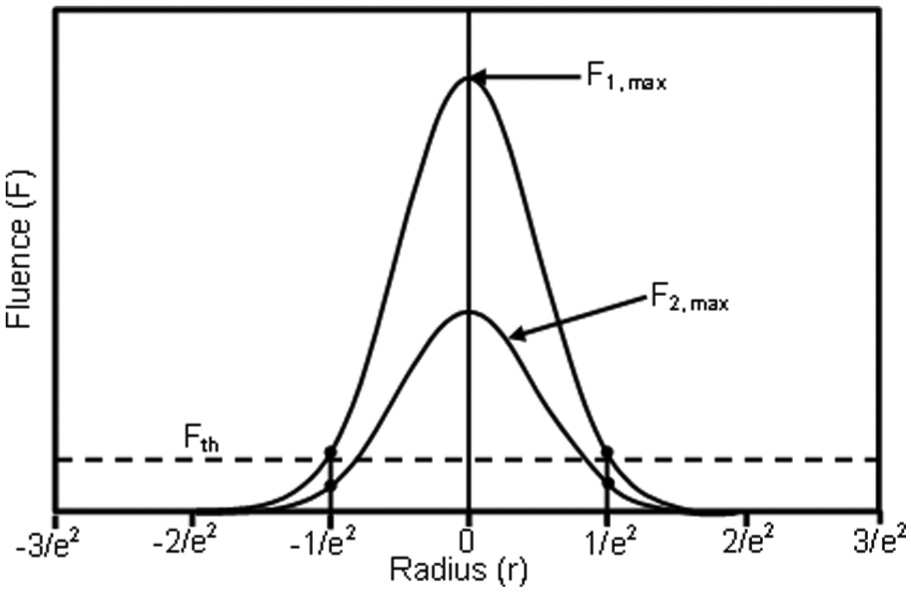
Schematic representation of Gaussian beam profile for different radiation fluence values.
Nevertheless, for the estimated number of laser pulses with the scan speed ranging from 50 to 200 mm/s and with other fixed parameters, groove width is not significantly changed. In other words, an increase in the number of laser pulses at low scan speed does not affect the groove width significantly. This is due to the change in optical properties of the irradiated surface after initial pulses and subsequent variation in the deposition depth of laser energy. The width of grooves remains almost constant for different scan speeds at a constant repetition rate, while groove depth decreases with an increase of scan speed. The energy from laser radiation accumulated in a unit area of sample decreases with an increase in scan speed, which makes a decrease in material removal, and hence the groove depth, as discussed earlier. By contrast, at the 300 mm/s tested, the effective number of pulses is small. As a result, only top hat of the Gaussian pulse with the fluence above the ablation threshold causes material removal, so that the groove width is small, so is the groove depth.
The roughness of groove surfaces is an important characteristic and has been studied previously 3 where it is found that the surface roughness of a single pulse irradiated germanium increases with the radiation fluence. In this study, the groove bottom surface was used for this analysis. As the grooves were machined due to the overlapping of irradiated spots, they exhibit a smooth central region. The groove bottom surface roughness (Ra) as a function of the radiation fluence at the scan speed of 50 and 200 mm/s measured over a distance of 63.5 µm using laser scanning microscope is presented in Figure 9. For a given pulse repetition rate and scan speed, surface roughness increases with the laser power. Irrespective of the pulse repetition rates, a significant change in roughness is observed with a scan speed of 50 mm/s (Figure 9(a)) as compared to 200 mm/s (Figure 9(b)). The low roughness at a high scan speed and repetition rate shows the possibility of using these parameters for micromachining of Ge. At a lower scan speed, a higher number of pulses per unit area increases the melting and re-solidification, which could increase the surface roughness. The large fluctuation of surface roughness for 1 MHz, as shown in Figure 9(a), is probably due to the variation of pulse energy and pulse width at this repetition rate or by experimental errors.
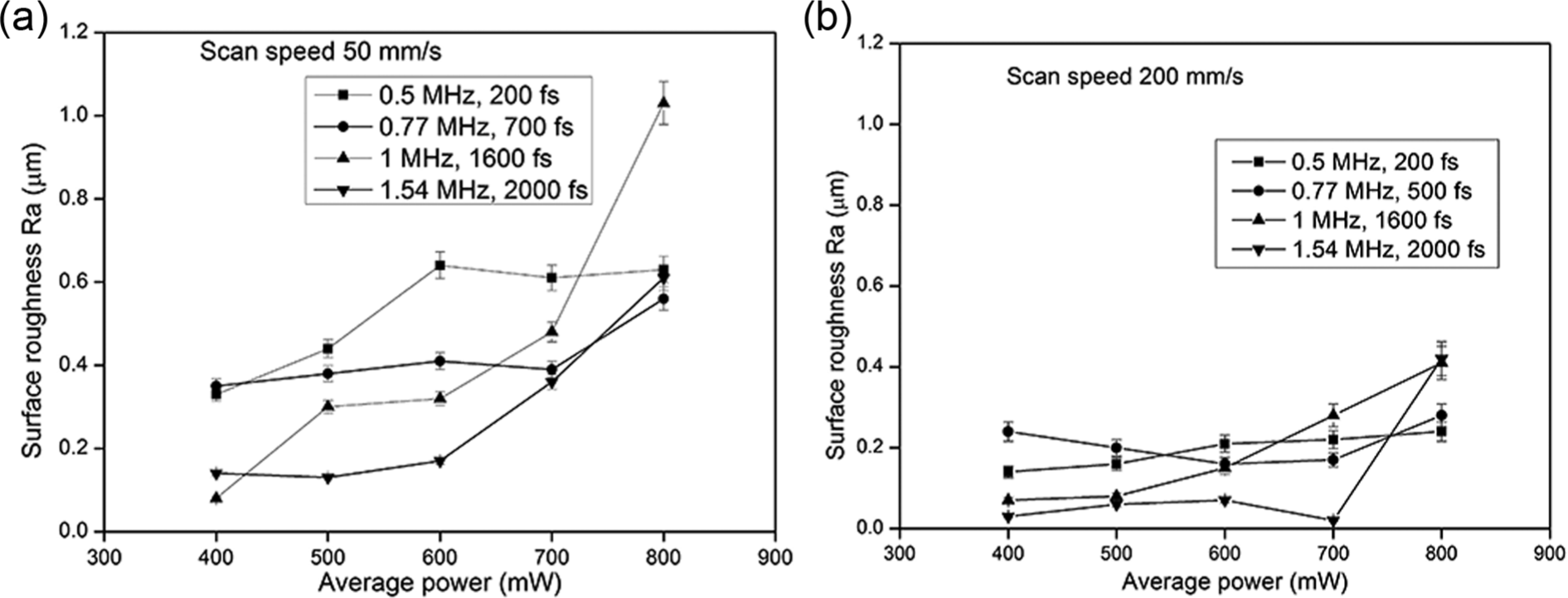
Effect of laser power and pulse repetition rate on the groove bottom surface roughness (Ra). (a) Scan speed 50 mm/s, (b) scan speed 200 mm/s
Micro-Raman analysis
A Raman spectroscopy analysis has been carried out, which reveals the crystallization properties of the material on the grooves. Raman effect is based on the inelastic scattering of laser photons with lattice vibrations (phonons) of the materials. In the lattice of a single crystal Ge, these phonons can propagate as a wave and exhibit dispersion depending on their wavelength. In the vibrational spectra of material, the consequences of phonon confinement are noticeable only when the grain size is smaller than 20 lattice parameters. When the material is irradiated with laser radiation below melting threshold, a small part of energy from incident photons is used to excite lattice vibrations (phonons). The remaining energy escapes as photons with a slightly smaller energy compared to that of incident photons. The difference in energy between incoming and the outgoing photons corresponds to the vibrational energy of the studied material. The shift in frequency observed in Raman scattering is, therefore, the characteristics of chemical bonds in the material. The analysis of the scattered frequencies can reveal information about the structural changes, impurities and residual strains of the material. Representative micro-Raman spectra for the unprocessed crystalline Ge and a groove surface machined with a pulse repetition rate of 0.5 MHz, laser power of 800 mW and a scan speed of 50 mm/s are shown in Figure 10. The Raman spectra of both unprocessed crystalline Ge and laser machined groove are fitted with Lorentz distribution. The peak position and full width at half maximum (FWHM) of the Raman spectrum can be the index of change in crystallinity. 28 In crystalline Ge, the momentum conservation law selects phonons with zero momentum, since photon momentum is negligibly small. As a result, only optical phonons with zero momentum lead to the sharp peak intensity at a Raman shift of 300 cm−1, as presented in Figure 10. The corresponding FWHM is 4.9 ± 0.2 cm−1. The peak intensity at 300 cm−1 is the characteristic of the first-order transverse optical (TO) phonon mode of crystalline Ge. The spectrum observed at the microgroove centre exhibits a slightly lower shift at 297.5 cm−1 for the Raman peak intensity and a larger FWHM of 7.5 ± 0.3 cm−1. Nevertheless, the spectrum is symmetric and does not exhibit any low-frequency components that characterize as the presence of amorphous Ge. A decrease in peak shift by 2.5 cm−1 with an increase of 2.6 ± 0.3 cm−1 for FWHM noticed in the Raman spectrum of the groove surface indicates a slightly broader, but still symmetric Raman mode, which suggests that the material is polycrystalline as compared with the unprocessed Ge. 29 This is attributable to recrystallization of molten Ge on the groove surface. Further work is being undertaken to study the thermally affected layer thickness and achieve ‘cold’ ablation so as to minimize the phase change of material using ultrashort pulsed lasers, similar to the work in the study by Wan et al. 27
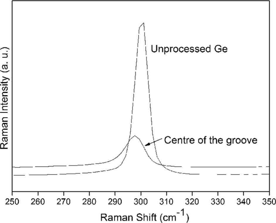
Micro-Raman spectrum of unprocessed crystalline Ge and the surface of a machined groove at laser pulse repetition rate of 0.5 MHz, laser power of 800 mW and a scan speed of 50 mm/s.
Conclusion
Microgrooving on crystalline Ge using ultrafast laser pulses under ambient conditions has been investigated. The influence of processing parameters such as average laser power, pulse repetition rate and scan speed on the groove depth, width and surface roughness has been studied. Furthermore, the ultrafast laser–material interaction mechanisms are discussed. Laser power and pulse repetition rate have been found to significantly affect the characteristics of grooves. The depth and width of the grooves increase with laser power. This is due to the increase in pulse energy with laser power, and subsequently, more energy is deposited into the material that results in a larger material removal. This effect is more pronounced at the lower scan speeds tested such as 50 mm/s due to an increase in the effective number of laser pulses applied. On the other hand, a decrease in pulse energy at low power (such as 400 mW) and the number of pulses at higher scan speed (such as 200 mm/s) cause a decrease in the groove depth and width. The surface roughness of microgrooves increases with laser power, but decreases with an increase in scan speed and pulse repetition rate. During multipulse irradiation, residual thermal energy of the material from each laser pulse plays a significant role in material removal. The interaction of first few pulses increases the absorption of laser energy for the subsequent pulses. This attributed to a change in the optical properties of Ge at higher temperature. A micro-Raman analysis reveals that the machined surface has changed to polycrystalline Ge, with a lower Raman shift below 300 cm−1 for the peak intensity and a broader Raman mode. By properly controlling the process parameters, ultrafast laser micromachining of crystalline semiconductor materials can provide good machining rate and machining quality.
Footnotes
Acknowledgements
The authors would like to thank Qi Wu for her help with the Raman spectroscopy study.
Declaration of conflicting interests
The authors declare that there is no conflict of interest.
Funding
This research received no specific grant from any funding agency in the public, commercial or not-for-profit sectors.