
Abstract
In this study, continuous microcrystalline diamond layer with grain size of 0.8–2 µm, nanocrystalline diamond layer with grain size less than 100 nm, diamond-like carbon layer with no apparent grains and TiAlN layer with small particles on the top surface are successfully deposited on cemented tungsten carbide-cobalt (WC-Co) samples and microdrills. Diamond peak of microcrystalline diamond film is quite definite in the Raman spectrum, while that of nanocrystalline diamond and diamond-like carbon coating is not so apparent. The roughness of microcrystalline diamond, nanocrystalline diamond, diamond-like carbon coating and TiAlN coatings is about 215.83, 144.4, 23.63 and 168.17 nm, respectively. Nanocrystalline diamond film exhibits lowest adhesive strength between substrate, while diamond-like carbon exhibits highest adhesive strength between substrate. Tribotests show stable friction coefficients of microcrystalline diamond, nanocrystalline diamond, diamond-like carbon and TiAlN coatings as about 0.28, 0.08, 0.08 and 0.4, respectively, while their wear rates against Si3N4 balls are 4.9E−7, 7.0E−7, 7.7E−7 and 2.9E−6 mm3 N−1 m−1, respectively. Microdrilling experiments show that the tool life of microcrystalline diamond–coated microdrill is as about 1.5, 2, 6 and 9 times more than that of nanocrystalline diamond-, diamond-like carbon-, TiAlN-coated and uncoated microdrills, respectively. The main wear types of these microdrills are flank wear, chipping and coating delamination. The results show that the microcrystalline diamond film is more suitable to be deposited on microdrills than the other three coatings to enhance cutting performance of microdrills in dry machining of graphite.
Introduction
Graphite is a widely used material for electrodes in electro-discharge machining (EDM) as it has unique properties compared with copper and stainless steel, for graphite crucibles to fabricate monocrystalline silicon in solar power industry and for conductors in semiconductor manufacturing processes.1,2 However, graphite is not easy to be machined due to the layered crystalline structure and, particularly, the extremely abrasive behavior of hard particles in graphite, which leads to a shortened tool life. 3 This problem may be worse for microcutting tools. As in micromachining, the tool life is reached very abruptly and generally catastrophically compared with the tools used in conventional machining. 4
Consequently, many methods are applied to improve the tool life of microcutting tools, such as optimizing tool material, tool geometry, coating strategy and cutting parameters.5–9 Among these methods, depositing thin hard film surface coatings on microcutting tools is found to be an effective way to extend the cost-effectiveness and efficiency of the production process in terms of improved surface quality, increased tool life span, reduction in machine downtime and reduction in risk of damage as a result of tool wear or breakages.10–12
Chemical vapor deposition (CVD) diamond coatings for microcutting tools are promising because of their potential to consistently maintain tool material as diamond has the most extreme properties such as excellent tribological properties and superior wear resistance.13–15 However, few literatures have focused on CVD diamond, especially nanocrystalline diamond (NCD)-coated microcutting tools in machining graphite to our knowledge. Meanwhile, diamond-like carbon (DLC) coating is also widely used as microcutting tool coating as it retains major properties of diamond, especially its excellent tribological properties.16,17 In most cases, diamond and DLC coatings are preferred to be deposited on microcutting tools because of their better wear resistance. However, due to its relatively low cost, high-performance TiAlN coating is of considerable interest and widely used in graphite manufacturing industries owing to the relatively high wear resistance of the coating and a superior toughness. 18
The review of the literatures mentioned above reveals the potential of adopting CVD diamond, DLC or TiAlN thin films in improving cutting performance of microcutting tools. But few literatures have systematically compared wear mechanisms of these widely used thin-film-coated cutting tools. Moreover, to our knowledge, comparative wear mechanisms of CVD diamond-, DLC- and TiAlN-coated microdrills in machining high-purity graphite are not reported in open literature till date. Our work concentrates on comparatively studying characteristics and tribological properties of CVD diamond, DLC and TiAlN coatings and their cutting performance when deposited on microdrills, aiming to find out the suitable thin films for microdrills when applied in graphite machining.
Experimental details
Substrate pretreatment and film deposition
Tungsten carbide–cobalt (WC-6% Co) microdrills with diameter of 0.4 mm and samples (13 × 13 × 3.175 mm) are used as substrates. Prior to CVD diamond deposition, a two-step chemical etching procedure is performed to properly remove the binder phase from WC-Co substrate surface because cobalt can induce interfacial graphitization. In our experiment, WC-Co samples are dipped in Murakami’s reagent for 30 min and followed by acid solution for 1 min, while the top part of microdrills is dipped in Murakami’s reagent and acid solution for only 5 min and 30 s to properly etch Co and meanwhile not to weaken stiffness of microdrills to a great extent. The deposition process is conducted in a homemade bias-enhanced hot filament chemical vapor deposition (HFCVD) apparatus. Two types of CVD diamond films, microcrystalline diamond (MCD) and NCD films, are coated on microdrills and samples, respectively. Detailed experimental procedure and deposition parameters for depositing MCD and NCD films are described in previous work done by our research group. 19
DLC films cover a wide range of films with different compositions and structures. The hydrogen content of the coating can be used for dividing the coatings into two major groups, namely, amorphous hydrogenated carbon films (a-C:H) and hydrogen-free hard carbon films. In our study, the a-C:H films are deposited on WC-Co microdrills and samples adopting the radio frequency (RF) plasma technique. Prior to deposition, the substrates are sputter-cleaned in an argon atmosphere for 10 min at a bias of −350 V and a pressure of 0.7 Pa. The ambient pressure in the deposition chamber is approximately 3.0 × 10⁻⁴ Pa. The TiAlN coating is processed in an industrial environment, and it is deposited on WC-Co microdrills and samples using enhanced catholic arc magnetron sputtering with deposition pressure of 0.8 Pa and substrate temperature of 500 °C.
Coating characterization
The surface morphologies of films on microdrills are estimated by field emission scanning electron microscopy (FESEM) (Zeiss Ultra 55). Atomic force microscopic (AFM) images are captured on WC-Co samples in tapping mode at room temperature in atmosphere by using Si tip probes with the radius of curvature of 10 nm. The contact angle and roughness measurements are carried out a few times at different locations to obtain average roughness values. The ingredients and purity of MCD, NCD, DLC and TiAlN films are examined by Raman spectroscopy. Rockwell C indentation tests are conducted on WC-Co samples to access the adhesion of these coatings by a Hoytom indentation instrument with load of 1000 N.
Friction tests
The tribological properties of MCD, NCD, DLC and TiAlN films are evaluated on a ball-on-disk wear test machine using pairs of CVD diamond-, DLC- and TiAlN-coated WC-Co samples and Si3N4 balls in open air at room temperature. The contact load is 4 N. The sliding velocity is kept at 0.22 m s−1. The Si3N4 ball is 6 mm in diameter. The ball-on-disk machine is instrumented with high-precision load cells, a high-capacity data acquisition system and control system to monitor frictional forces and to obtain friction coefficient throughout the test. After friction test, the cross-sectional wear profiles of these thin films are acquired by surface profile meter. The cross-sectional wear profile is then fitted with Gaussian curve to estimate its area. The wear rates of these films are determined by the wear volume loss divided by normal load and total sliding distance.
Cutting tests
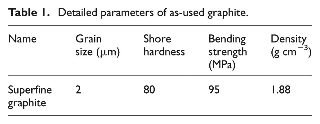
The cutting performance of CVD diamond-, DLC-, TiAlN-coated and uncoated microdrills is evaluated by dry drilling of commercial graphite blocks (ISO88; Toyo Tanso). Detailed parameters of the graphite are listed in Table 1. The feed rate is 0.06 mm rev−1, the depth of holes is 1.3 mm and the spindle speed is 15,000 r min−1. The tests are performed on a computer numerical control (CNC) graphite carving machine. The drilling tests are interrupted at intervals to examine the tool wear of cutting tools by FESEM. An ultrasonic cleaning for 15 min was performed in order to remove any particles that would mask tool wear. After cutting tests, FESEM is used to reveal the wear mechanisms, in addition with energy-dispersive spectroscopy (EDS; Oxford INCA 300) for local chemical analysis.
Detailed parameters of as-used graphite.
Results and discussion
Characterization of as-deposited coatings
The surface morphologies of as-fabricated MCD-, NCD-, DLC- and TiAlN-coated microdrills are investigated using FESEM. Figure 1 shows cutting parts (M1, N1, D1, T1) and enlarged morphologies of cutting corner (M2, N2, D2, T2) and planar point (M3, N3, D3, T3). It is found that the coatings display good uniformity and excellent coverage. The grain size of MCD is about 0.8–2 µm. For NCD films, the grain size falls to less than 100 nm. Surfaces of DLC film still display features with a preferential direction resulting from the DLC coating over the initial feed marks in the as-ground surface, and no grains could be seen in this film. It is clear that there are some white Al2O3 particles and dimples dispersed on the gray surfaces of TiAlN coatings. 20 The apparent size of some large particles is about 1.5 µm.
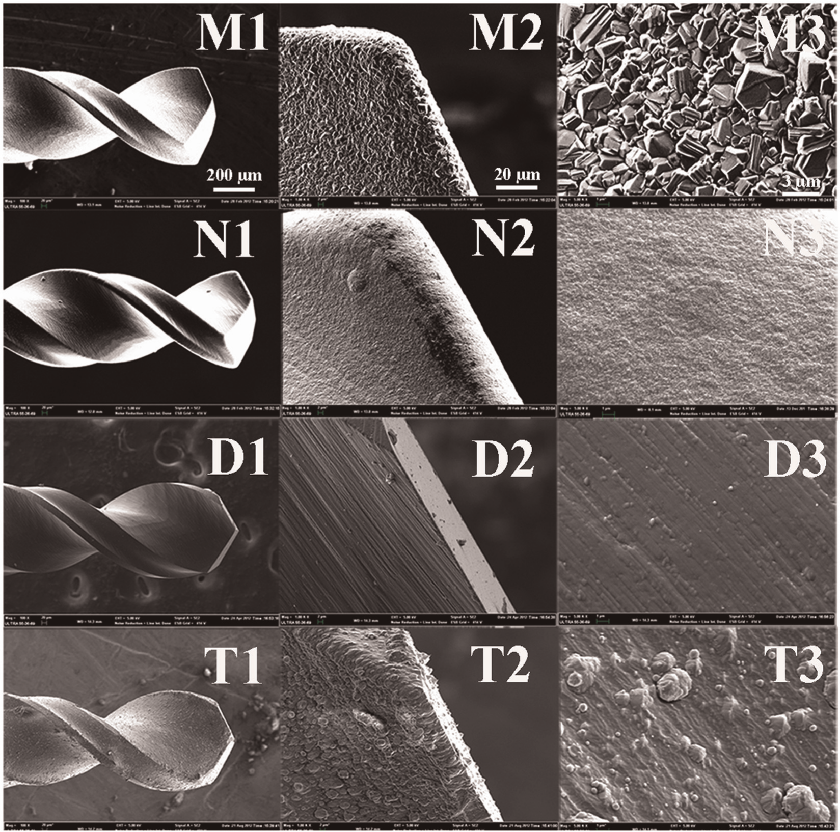
Surface topographies of as-deposited MCD (M1, M2, M3), NCD (N1, N2, N3), DLC (D1, D2, D3) and TiAlN (T1, T2, T3) films on microdrills.
Micro-Raman spectroscopy equipped with 632.8 nm He-Ne laser light excitation is employed to assess the quality of as-deposited films on microdrills. Detailed studies are carried out in the range of 800–1800 cm−1 (Raman spectral range), which give useful information about the distinctive diamond deposits, while useful information about TiAlN film is in the range of 100–800 cm−1 (Raman spectral range), as plotted in Figure 2. In the Raman spectrum of MCD film, there is only a sharp peak near 1332 cm−1, which indicates the extraordinary purity of diamond. However, the Raman spectrum of NCD film shows a broad peak around 1340 cm−1, which is due to the presence of sp2-bonded diamond structure (D peak). 21 The broad peak at 1580 cm−1 (G peak) may be attributed to sp2-bonded carbon residing at grain boundaries. The band near 1150 cm−1 is shown to be related to the calculated phonon density of states of diamond and has been assigned to the presence of nanocrystalline phase of diamond.22,23
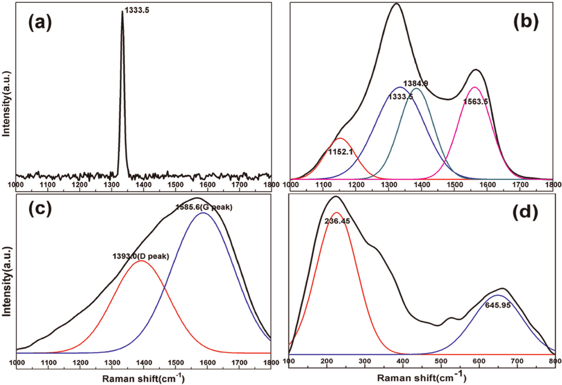
Raman spectra of as-deposited (a) MCD-coated, (b) NCD-coated, (c) DLC-coated and (d) TiAlN-coated microdrills.
DLC film consists of various carbon-related species, such as sp3 type bonding (diamond), carbon with sp2 type bonding (graphite) and carbon in mixtures of these two types of bonding (DLC). 24 Typically, the Raman spectra of as-deposited a-C:H film are considered to depend mainly on the clustering of the sp2 phase, the presence of sp2 rings or chains and the sp2/sp3 bonding ratio, and these factors act as competing forces on the shape of the Raman spectra.25,26 In Figure 2(c), Raman spectra of a-C:H film could be fitted with two Gaussian distributions to extract the characteristics of the D-peak and G-peak positions. The G peak is due to the bond stretching of all pairs of sp2 atoms in both rings and chains, which is located in the range of wave number 1560–1580 cm−1, while the D peak is due to the breathing modes of rings, and which spreads over the range of 1384–1405 cm−1. Comparing the Raman spectrum of MCD, NCD and DLC films, it can be seen that the characteristic first-order diamond Raman spectrum of MCD film is strongest and that of NCD is weaker. Furthermore, there is no diamond peak in the Raman spectrum of DLC films. It suggests that the content of sp2 bonding of diamond in MCD film is less than that of NCD and DLC films, which may indicate that hardness of MCD film is higher than that of NCD and DLC films.
It is noted that the Raman spectrum of the TiAlN coating mainly consists of two broad bands centered at 236.45 and 645.95 cm−1, respectively. These two bands are typical in the Raman spectrum of TiAlN films. 27
AFM images of the MCD, NCD, DLC and TiAlN films are shown in Figure 3. As can be seen in these pictures, MCD film has a granular morphologies, which degrade the uniformity and thus result in a relatively higher local roughness (Rq = 215.83 nm). As the grain size of NCD film is smaller, many defected grain boundaries are filled with amorphous carbon and graphite, and roughness of NCD film is lower (Rq = 144.4 nm). DLC coating exhibits quite low (Rq = 23.63 nm) local roughness as no perceptible grains are visible in this film. It is discernible in AFM image of TiAlN coating that there are many ups and downs as small Al2O3 particles are uniformly distributed on the surface of coating. So roughness (Rq = 168.17 nm) of TiAlN film is much higher than that of DLC film and comparable with that of NCD coating.
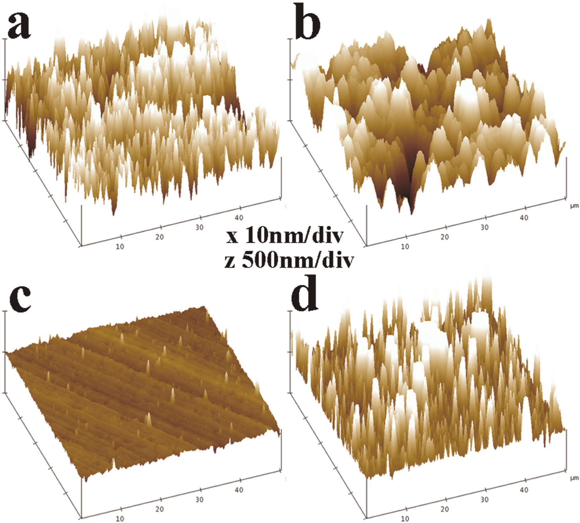
AFM images for (a) MCD, (b) NCD, (c) DLC and (d) TiAlN coatings.
The Rockwell C indentation tests are conducted on the MCD-, NCD-, DLC- and TiAlN-coated tungsten carbide samples to evaluate their interfacial coating–substrate adhesive strength. Figure 4 presents SEM images of MCD, NCD, DLC and TiAlN coatings with enlarge rates of 100 (M1, N1, D1, T1) and 1500 (M2, N2, D2, T2) following indentation. Three distinct failure modes, namely, plastic deformation, radial cracks and a detached annular area of coating around the indentation, are visible in these images. It is worth noting that the occurrence of microcracks and detached coating around the indentation is shown on MCD film, but the detached area is considerably smaller than that of NCD film. It is suggested that the adhesion between MCD film and substrate is stronger than that of NCD film. From images with higher enlarge rate, differences in adhesion of these two films between substrates could be seen, as depicted in Figure 4 (D2, T2). Only plastic deformation is visible at some areas on DLC film after indentation. This failure mode is indicative of DLC coating with good adhesion properties while micro-radial cracks can be seen on TiAlN film, which suggests that adhesion of TiAlN coating between WC-Co substrate is not as good as that of DLC film but better than that of MCD and NCD films.
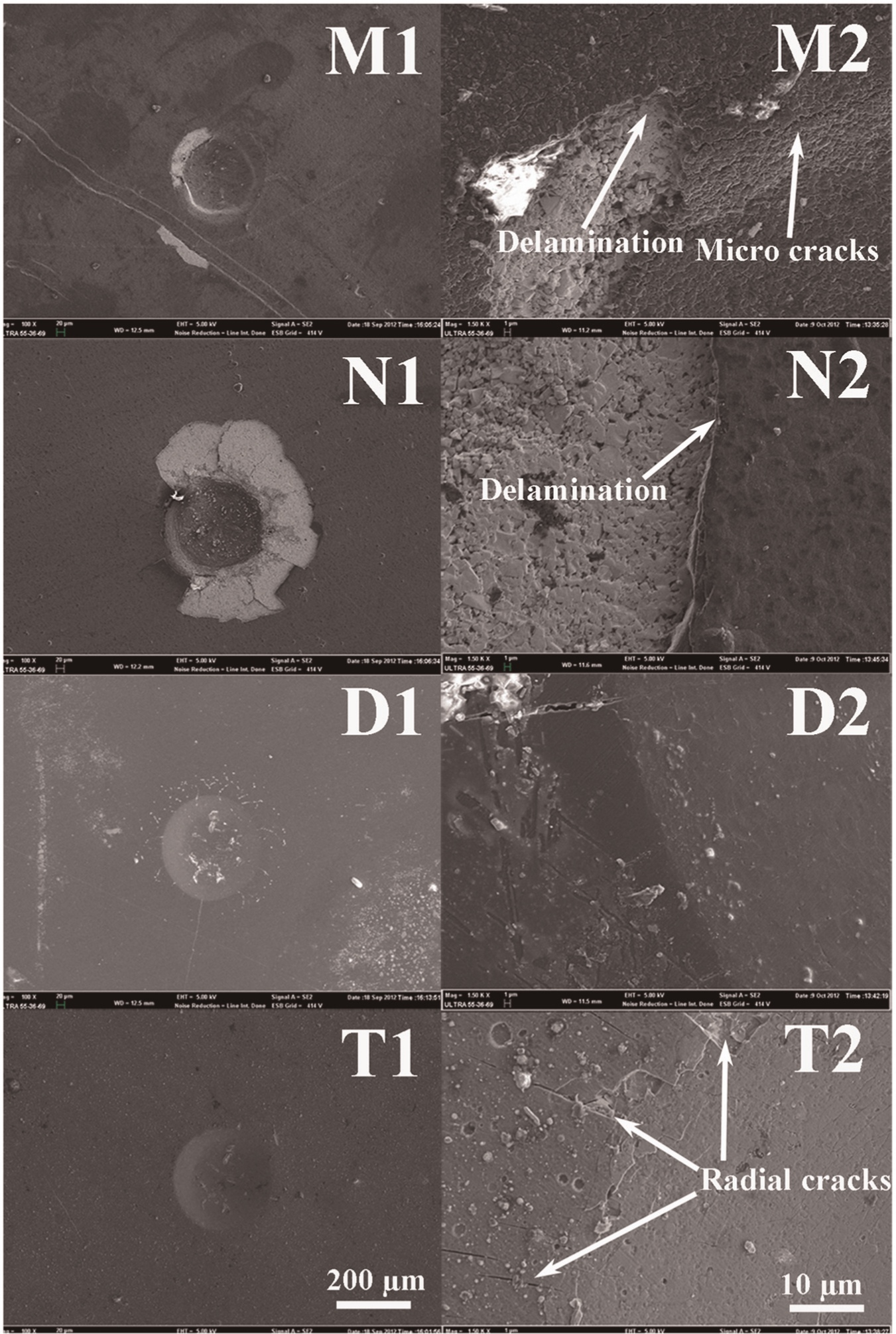
Typical coating failure modes of coatings following indentation: MCD (M1, M2), NCD (N1, N2), DLC (D1, D2) and TiAlN (T1, T2) coatings.
Friction behaviors
In order to understand wear mechanisms of these thin-film-coated microtools under the harsh conditions developed during dry machining operations, the resulting tribological interface must be investigated as a system in terms of the fundamental friction coefficients and wear rates of these coatings by friction tests. 28 Figure 5 plots the friction coefficient curves as a function of sliding time for MCD, NCD, DLC and TiAlN films sliding against ball-bearing Si3N4 counterfaces under dry sliding environment. All sliding contacts exhibit a stable state after experiencing a “run-in” period. It can be seen that high friction coefficients generally appear at preliminary part of TiAlN coating, which may attribute to the interlocking effect of sharp-shaped Al2O3 asperities distributed on the sliding interface. Once the Al2O3 solid particles are removed from the contact area, the friction coefficient of TiAlN film decreases rapidly as sliding continues and stabilizes at 0.4. Noting that the friction coefficient of MCD film is fairly stable and its value is 0.28. The average friction coefficients of the contacts during the stable period of DLC and NCD coatings stabilize at 0.08, which is much lower than that of TiAlN and MCD films.
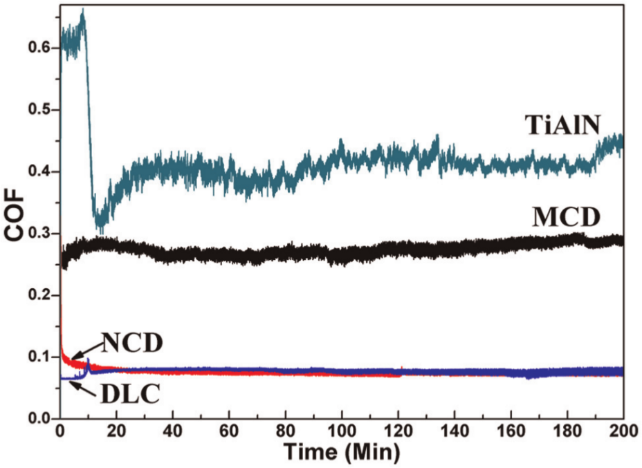
Friction coefficient curves for as-deposited MCD, NCD, DLC and TiAlN films.
After friction test, the calculated wear rates of these thin films are plotted in Figure 6. MCD film exhibits lowest wear rate (4.9E−7 mm3 N−1 m−1), while wear rate of TiAlN film (2.9E−6 mm3 N−1 m−1) is much higher than those of the other three films. In general, materials with high hardness and stiffness have superior wear resistance. Diamond represents a prime example, with its highest hardness and extreme wear resistance. 29 Compared with NCD and DLC films, as there are more content of sp3 bonding of diamond in MCD film, it exhibits higher hardness, which may be the reason for difference in wear rate among these three films.30,31 It is noted that hardness of TiAlN is comparable with that of DLC film. 32 However, its wear rate is much higher than that of DLC film, which may be attributed that stiffness of DLC film is higher than that of TiAlN film.
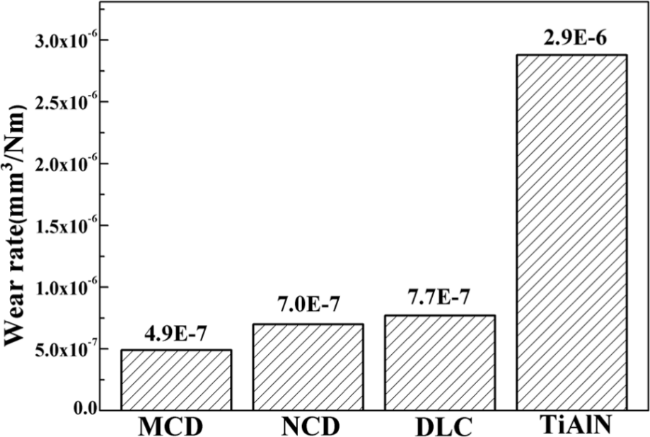
The wear rate of MCD, NCD, DLC and TiAlN thin films.
Cutting performance
The cutting performance of MCD-, NCD-, DLC- and TiAlN-coated microdrills is tested by dry drilling of graphite. For the sake of comparability, the uncoated microdrill is also involved. In general, coatings would increase the radius of cutting edges to a certain extent, but the thickness of as-deposited films is only 1–2 µm so that it may not affect the cutting performance of drills. Figure 7 presents the images of flank faces of MCD, NCD, DLC and TiAlN after drilling a certain amount of holes. Figure 8 shows the flank wear values for all the examined microdrills as function of drilled holes. As exhibited, flank wear of bare microdrill surpasses 30 µm after 1200 drilled holes. Comparatively, TiAlN-coated microdrills show flank wear of 18 µm during the initial 1200 drilled holes. Moreover, there is much less flank wear, only about 8 µm on MCD-, NCD- and DLC-coated microdrills. It means that thin hard films could effectually protect cutting edges from wear. During drilling 1200–3600 holes, TiAlN-coated microdrill exhibits a steady rise on its flank wear, reaching the value of 30 µm after drilling 3600 holes, while the MCD-, NCD- and DLC-coated microdrill shows much less flank wear, only 12, 14 and 16 µm, respectively. If flank wear value of 12 µm is thought as the tool life criterion of these microdrills, tool life of MCD-coated microdrill is as about 1.5, 2, 6 and 9 times more than that of NCD-, DLC-, TiAlN-coated and uncoated microdrills, respectively.
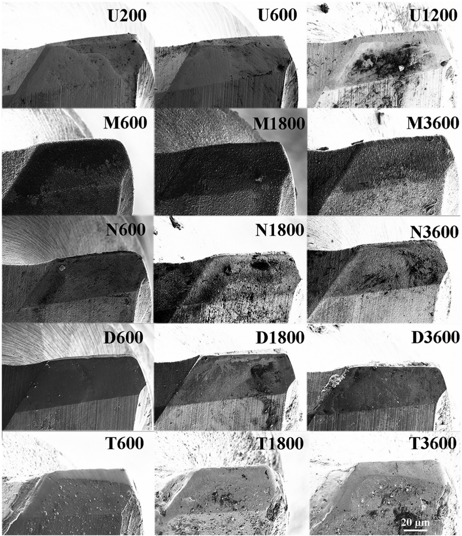
SEM images of flank faces on uncoated (U200, U600, U1200) and MCD-coated (M600, M1800, M3600), NCD-coated (N600, N1800, N3600), DLC-coated (D600, D1800, D3600) and TiAlN-coated (T600, T1800, T3600) microdrills after drilling 200, 600, 1200, 1800 or 3600 holes.
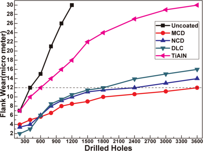
The measured flank wear for uncoated and MCD-, NCD-, DLC- and TiAlN-coated microdrills as a function of drilled holes.
After drilling, SEM images of flank faces with higher magnification are caught, and EDS is used to analyze the composition of two points located in and out of flank wear zone, as shown in Figure 9. Compared with the elementary composition of these two locations, it can be concluded that whether coating failure appears on the cutting edge. The elementary compositions in and out of flank wear zone of MCD-coated (Figure 9 (M1, M2, M3)) microdrill are generally consistent. It shows that the main element at these two points is carbon, which is the component of diamond coating, which suggests that the MCD coating at the cutting edge is not peeling off after drilling 3600 holes. For NCD-coated (Figure 9 (N1, N2, N3)) and DLC-coated (Figure 9 (D1, D2, D3)) microdrills, the composition in flank wear zone changes apparently after drilling, which indicates that NCD and DLC films are absent at cutting edges after drilling. It is noted that element oxygen is present out of flank wear zone on TiAlN-coated (Figure 9 (T1, T2, T3)) microdrill but absent in flank wear zone, which may be attributed to that Al2O3 particles at the surface of TiAlN coating is rubbing away during machining. Meanwhile, the elementary composition in flank wear zone shows that nitrogen, aluminum and titanium are still dominated; thus, TiAlN coating is not peeling off from substrate.
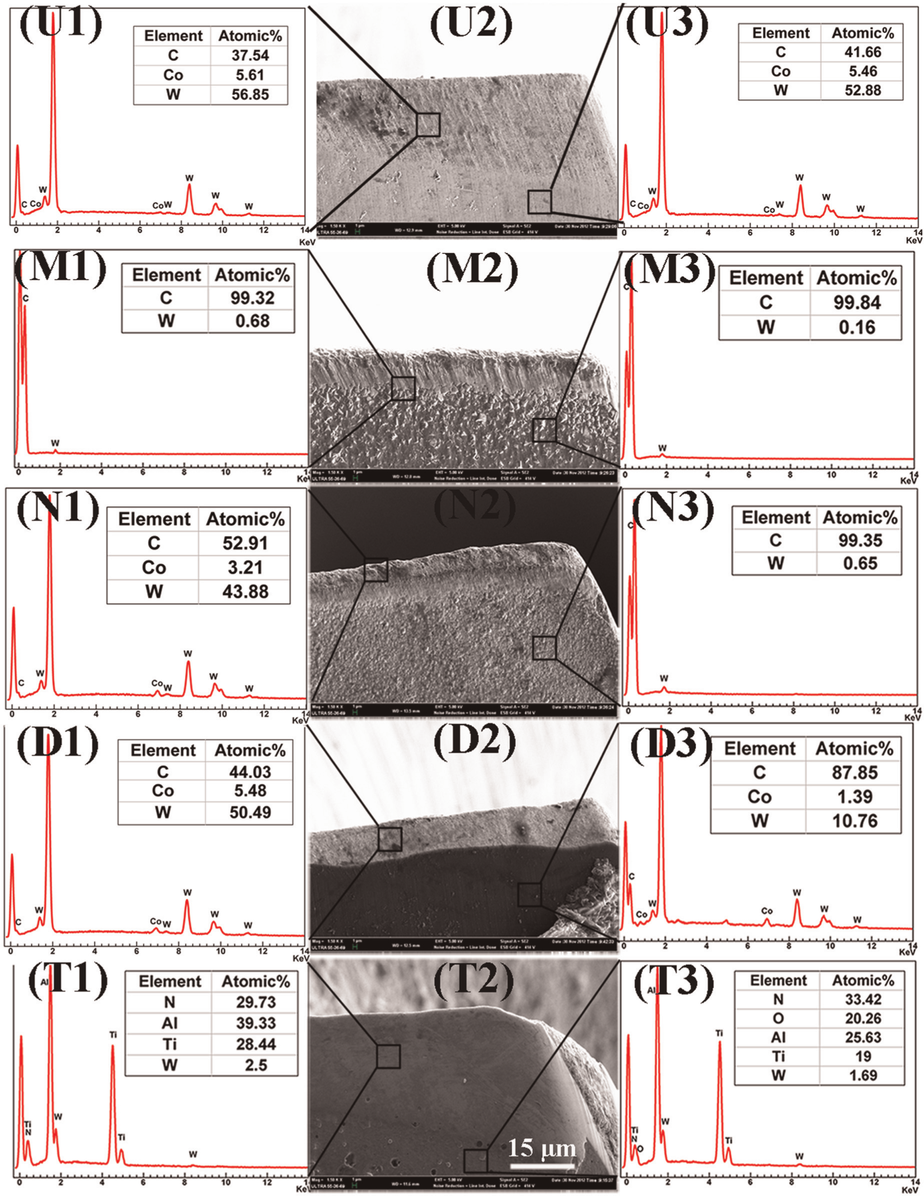
FESEM images and EDS analysis of main cutting edges on uncoated (U1, U2, U3) and MCD-coated (M1, M2, M3), NCD-coated (N1, N2, N3), DLC-coated (D1, D2, D3) and TiAlN-coated (T1, T2, T3) microdrills.
In graphite machining, when the graphite is crushed into small particles and fine dust, the cutting tool suffers high impact and compressive stress at the tool tip. The mechanical stress induced by the extreme compressive pressure of crushing graphite powders is one typical tool failure mode during graphite machining, which is the main course of chipping and coating delamination at cutting edges on cutting tools. At the same time, the graphite chips are slipping away from cutting zone due to the pushing of newly generated graphite powders in cutting zone. The relative movement between cutting tool and workpiece would cause severe abrasive wear on cutting tools. Consequently, abrasive wear is another typical tool failure mode during graphite machining.
After drilling, it could be seen that TiAlN-coated microdrill exhibits considerably more flank wear than MCD-, NCD- and DLC-coated microdrills. And among MCD, NCD and DLC microdrills, flank wear of MCD-coated microdrills is the lowest. This result is quite in accordance with the wear rate results from friction test. As MCD film has the best wear resistance, the severe abrasive wear during graphite machining results in lowest flank wear on MCD-coated microdrills.
It is noted that although the friction coefficients of NCD and DLC coatings are lower than that of MCD film, flank wear of NCD- and DLC-coated microdrills after drilling is higher than that of MCD-coated microdrills. It shows that friction coefficient of thin hard films has less impact on wear of microdrills in graphite machining.
In Figure 9 (N2), chipping and coating delamination are observable on NCD-coated cutting edges after drilling. The reason may be attributed to the lack of good adhesion between NCD film and substrates; thus, NCD coating at cutting edge could not afford the mechanical stress induced by the high compressive pressure of crushing graphite powders. It is noted that coating peeling off could also be seen on cutting edge of DLC-coated microdrills. Nevertheless, its principle of delamination is quite different from that of NCD film as the adhesive strength of DLC coating is quite high, it is not likely to be peeled off from substrate. As wear resistance of DLC film is not as good as NCD film, DLC film may be worn away by graphite chips instead of coating delamination.
After drilling, MCD-coated microdrills exhibit minimal flank wear. Meanwhile, no coating peeling off could be seen besides flank wear. This is attributed to the relatively satisfactory adhesion between substrates and superior wear resistance of MCD films. In general, MCD film is more suitable to be deposited on microdrills than the other three coatings to enhance cutting performance of microdrills in graphite machining.
Conclusions
MCD, NCD, DLC and TiAlN films are successfully deposited on WC-Co microdrills. The content of sp3 bonding of diamond becomes very less from MCD coating to NCD and DLC films. Local roughness of MCD, NCD, DLC and TiAlN coatings are 215.83, 144.4, 23.63 and 168.17 nm, respectively. DLC coating exhibits highest adhesive strength between substrates among these films, while NCD has lowest adhesive strength between substrates. The friction tests show friction coefficients of MCD, NCD, DLC and TiAlN coatings as about 0.28, 0.08, 0.08 and 0.4, respectively, while their wear rates against Si3N4 balls are 4.9E−7, 7.0E−7, 7.7E−7 and 2.9E−6 mm3 N−1 m−1, respectively.
Comparative drilling tests involving MCD-, NCD-, DLC- and TiAlN-coated and uncoated WC-Co microdrills in graphite machining reveal apparent cutting performance enhancement by using MCD-, NCD-, DLC- and TiAlN-coated microdrills compared with bare ones due to comparatively higher hardness, thus better wear resistance of these films. Tool life of MCD-coated microdrill is about 1.5, 2, 6 and 9 times more than that of NCD-, DLC- and TiAlN-coated and uncoated microdrills, respectively. The growth rate of flank wear on MCD-, NCD-, DLC- and TiAlN-coated microdrills in drilling experiments is similar to wear rate of these films in friction tests. Meanwhile, coating delamination occurs on NCD-coated microdrills. MCD-coated microdrill exhibits minimal flank wear, no chipping and coating delamination after drilling; thus, MCD film is more suitable to be deposited on microdrills than the other three coatings to enhance cutting performance of microdrills in graphite machining.
Footnotes
Declaration of conflicting interests
The authors declare that there is no conflict of interest.
Funding
This research was supported by the National Natural Science Foundation of China (numbers 51275302 and 51005154), the Chenguang Program of Shanghai Municipal Education Commission (number 12CG11) and the Tribology Science Fund of State Key Laboratory of Tribology (number SKLTKF10B02).