
Abstract
Extrusion container is the most important tooling in steel hot extrusion processing. Traditional designs such as the multilayered cylinder are difficult to execute for large extrusion containers. A novel design is proposed in this article, a salient feature of which is that the container employs steel wire winding technology. The primary difficulty of applying wire winding to the design of extrusion container is that the container should be heated to 350 °C while the temperature of steel wire cannot exceed 75 °C due to accelerated creep and stress relaxation at high temperature. In addition, the prestress generated by steel wire should fulfill the requirements necessary for the container. The proposed design should meet both goals. The functional requirements including preheating, protection of steel wire from high temperature, and stress distribution are discussed, and solutions are proposed. A new method to generate prestress called thermally induced prestress is introduced and detailed. To verify the design, a proof-of-concept prototype model was fabricated and tested. Results showed that the container using the proposed design could meet the expected prestressing goals, and the temperature of the wire would not exceed the limit and can offer an alternative to conventional design methods of extrusion containers.
Introduction
The glass-lubricated steel hot extrusion process was invented by Sejournet and has been applied worldwide to fabricate high-quality steel bars, tubes, and profiles as well as other advanced alloy products.1,2 To effect this process, first and foremost, the appropriate lubrication between the billet and tooling needs to be defined. The solution to this problem centers on coating the hot billet with a layer of glass to provide lubrication between the billet and extrusion container. In addition, a glass pad is placed at the front end of the billet to avoid direct contact with the extrusion die. As the metal flows out, a thin layer of softened glass lubricant is generated, which simultaneously provides lubrication and thermal insulation to prevent high temperature abrasion of the die.3,4 The process is shown in Figure 1.
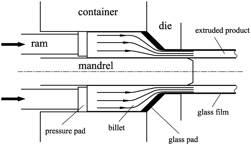
Schematic representation of extrusion process.
Another formidable challenge in this process is the design of extrusion container, which is the most expensive tooling. For large steel tube extrusion, the pressure between the billet and container is usually over 200 MPa while internal surface temperature can attain 600 °C. The large dimensions and weight of the container make it difficult to manufacture.5,6
The earliest containers were single cylinder; however, this design has since been abandoned due to its poor performance.7,8 Currently, the most widely used containers are multilayered, usually consisting of three layers of cylinder. A typical feature of the design is that the prestress is generated by the interferences between the multiple cylinder layers.9,10 The loading capacity is greatly enhanced in comparison to single-cylinder extrusion container. Until now, the prestressed multilayered extrusion container has been the most prevalent design. However, large extrusion containers have been difficult to manufacture, because the layers were made of large forgings, particularly the outer cylinder. To solve this problem, the Baldwin-Lima-Hamilton Corporation proposed a solution, as shown in Figure 2. 11 As shown, the outer cylinder is divided into a series of rings positioned side by side along the length of the container. Prestress is generated by the interference between the rings and the middle cylinder. In addition, grooves are present between the rings, which house heating and temperature control units. Dividing the outer cylinder into a series of rings facilitates the manufacture of the container. However, this process does not reduce the dimensions and weight of the container design. This is because the parameter K, defined by the ratio of the external diameter and the internal diameter of the container, is too large (K = 4–5). As an example, the largest container used for the 360 MN vertical extrusion press built by China North Heavy Industry Group (Baotou, China) has an internal diameter of 1700 mm. In this instance, if K = 4, the outer diameter would be 6800 mm and the weight would be over 400 ton. Under the conditions, the interferences between each layer would make the cylinder very difficult to assemble.
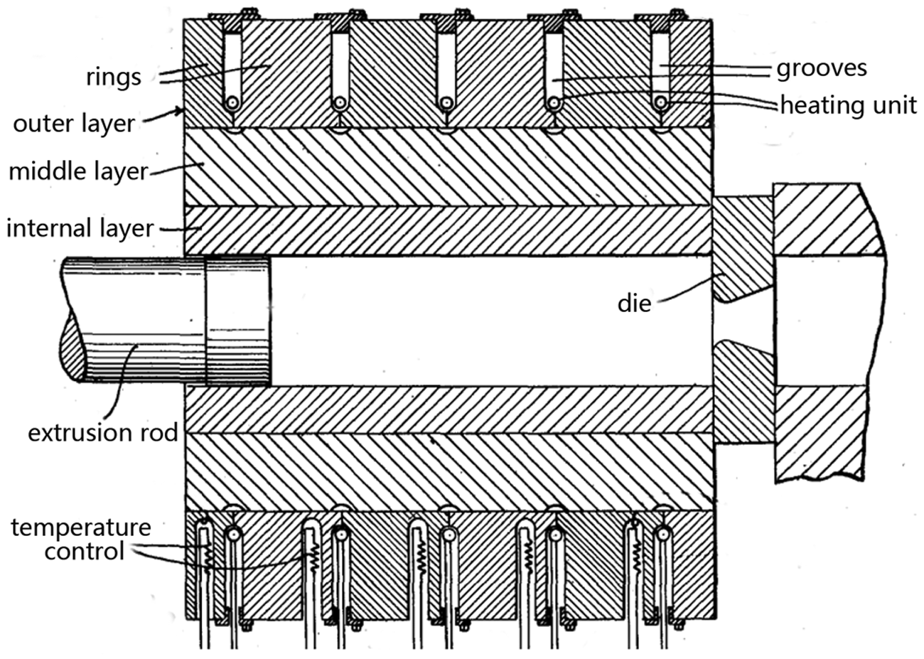
Multilayered extrusion container.
To reduce the large weight and high cost of the container, we have developed steel wire wound extrusion containers for large steel tube extrusions. Steel wire winding technology offers many advantages over traditional prestressing techniques such as interference fitting and bolt prestressing. The major advantage lies in the high tensile strength of the wire due to its small cross-sectional area. Normally, the allowed stress can attain up to 850 MPa or greater for commonly used 65Mn steel wire, which makes it a unique tool for prestressed engineering structures. Due to its high tensile strength, the thickness of the prestressed layer can be greatly reduced. Until now, steel wire winding has been widely used to fabricate large frames, large hydraulic cylinders, ultrahigh pressure vessels, and other structures12–15 but is applied primarily to engineering structures used at room temperature. The application of steel wire winding to engineering structures used at high temperature like large extrusion containers has not been previously reported. For extrusion containers, the weight of the wire wound container can be decreased from 400 to 150 ton. This attribute makes it attractive to develop this type of extrusion containers. However, there are problems when steel wire winding is applied to extrusion containers. The container must be preheated to over 350 °C in order to avoid immediate thermal shock of the 1150 °C–1250 °C steel billet, while the temperature of steel wire must be kept below 75 °C to minimize accelerated creep and stress relaxation of the steel wire at high temperature. 16 At the same time, the prestress generated by steel wire throughout the container should counteract the tensile stress caused by the internal pressure. Therefore, the design of steel wire wound containers is a multifaceted problem, which can be summarized as follows:
Preheat the container to over 350 °C while the wire is maintained below 75 °C.
The prestress throughout the container must satisfy the requirements.
The design described in this article is proposed to meet both goals.
Creep behavior of 65Mn steel wire
To determine the maximum allowed temperature of 65Mn steel wire that is often used as prestressing tool, the creep behavior of 65Mn steel wire was tested at different stress levels and different temperatures. 17 The testing device is shown in Figure 3.
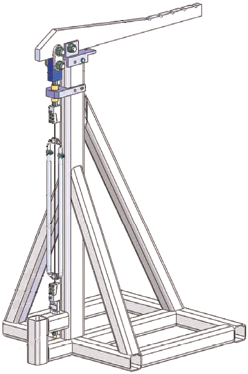
Testing device for creep behavior of 65Mn steel wire.
The total strain when the steel wire is loaded is composed of three components
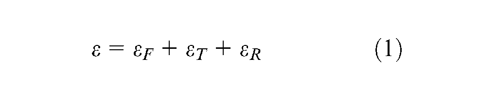
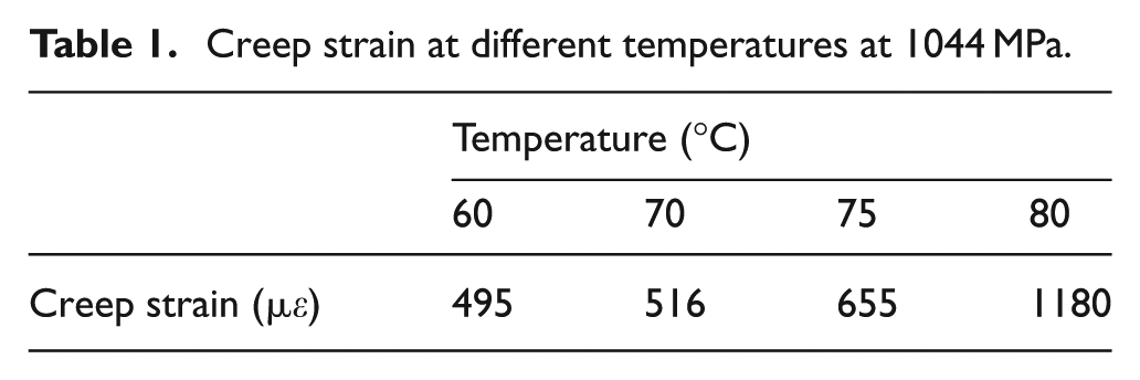
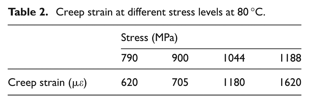
where εF is the elastic strain, εT is strain induced by temperature changes, and εR is creep strain. At room temperature, the creep strain is 219 µε (at 1044 MPa), which is only 4.3% of the elastic strain (5075 µε). Thus, for room temperature steel wire wound structures, creep behavior has little effect on prestress. To observe creep behavior at elevated temperatures, experiments were conducted at different stress levels (792, 900, 1044, and 1188 MPa) and different temperatures (60 °C, 70 °C, 75 °C, and 80 °C). The measured creep strain variation with stress and temperature is shown in Tables 1 and 2. It can be seen that the creep strain increased dramatically when the temperature exceeded 75 °C but increased slowly below 75 °C at 1044 MPa. Similarly, the creep strain varied in the same manner when the stress was less than 900 MPa and exceeded 900 MPa at 80 °C.
Creep strain at different temperatures at 1044 MPa.
Creep strain at different stress levels at 80 °C.
In general, it is preferred that the temperature of steel wire should not exceed 75 °C to prevent a significant increase of creep strain and loss of prestress.
Analysis on the design of steel wire wound containers
The basic structure of steel wire wound extrusion container is shown in Figure 4. 18 In total, there are four layers including the internal, the middle, the external cylinder, and steel wire. The internal and middle cylinders are prepared from hot-working die steel. The external cylinder is composed of cast die steel and divided into four pieces. The layers are assembled on the condition of transition fit and wrapped up by tensioned steel wire. The wire provides prestress throughout the container, and the loading capacity is greatly enhanced since all the layers are in the compression stress state and all the tensile stress is borne by the steel wire. Figure 4 depicts the basic concept of the container.
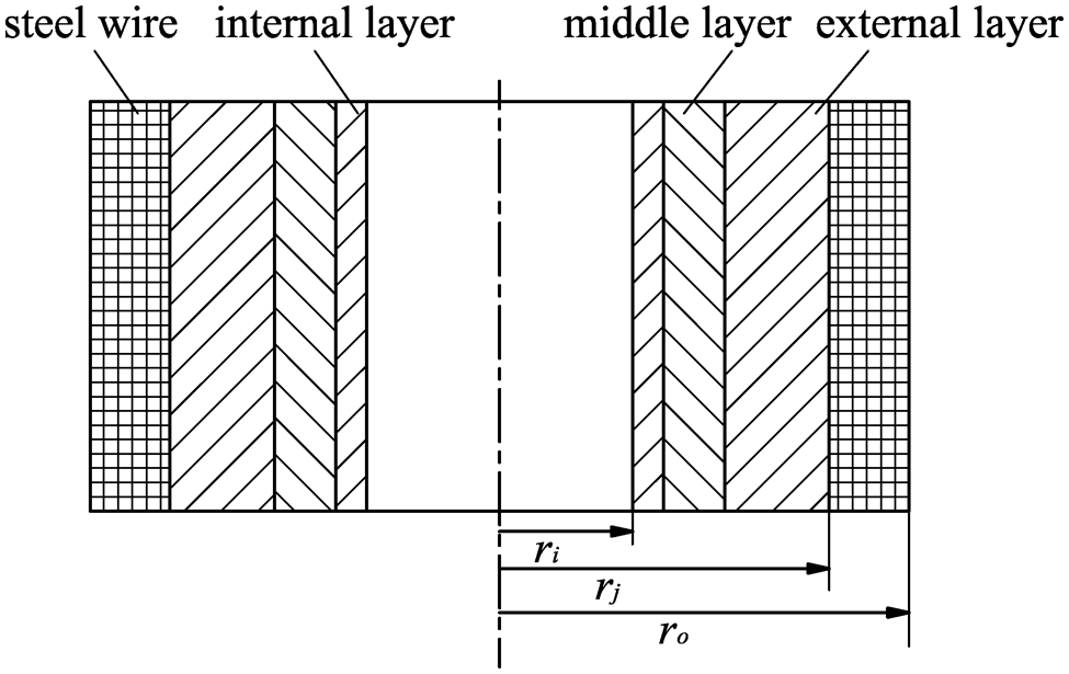
Basic structure of steel wire wound extrusion containers.
Determination of structural parameters
Usually, a prestress coefficient η is used to characterize prestressed structures. 7 For the extrusion container, η is defined as
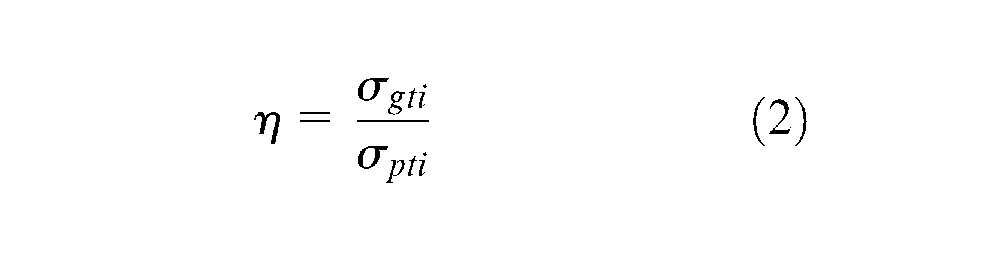
where σgti is the tangential stress produced by prestress and σpti is the tangential stress produced by the internal pressure. The coefficient η represents the level of prestress. If η = 1, the tangent stress induced by internal pressure is totally counteracted by prestress.
σpti can be calculated from Lame’s equation
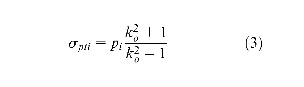
where pi is the internal pressure and ko = ro/ri (the ratio of the external radius and internal radius). In this example, we depict an extrusion container with the internal diameter of 1700 mm designed for a 360 MN extrusion press. The values of the salient parameters are η = 1, pi = 200 MPa, ri = 850 mm, and ro = 1900 mm. With this in mind, it can be computed that σpti = 300 MPa. The parameters that need to be computed include the outer radius of the inner cylinder r1, the outer radius of the middle cylinder r2, and the inner radius of the wire layer rj.
A wire winding method to make the shear stress of the internal and external layers of steel wire equal under the load of internal pressure was proposed by Yan and Yu. 7 According to the equation
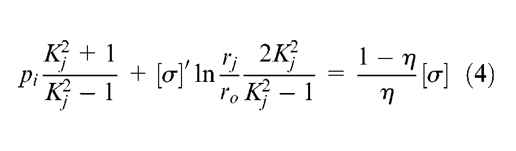
where Kj = rj/ri, rj is the inner radius of the wire layer, [σ]′ is the allowed stress of steel wire (usually 700 MPa), and [σ] is the allowed stress of the internal cylinder. This yields a computed rj = 1580 mm.
Then, the pressure that steel wire acts on the external cylinder σgrj can be calculated
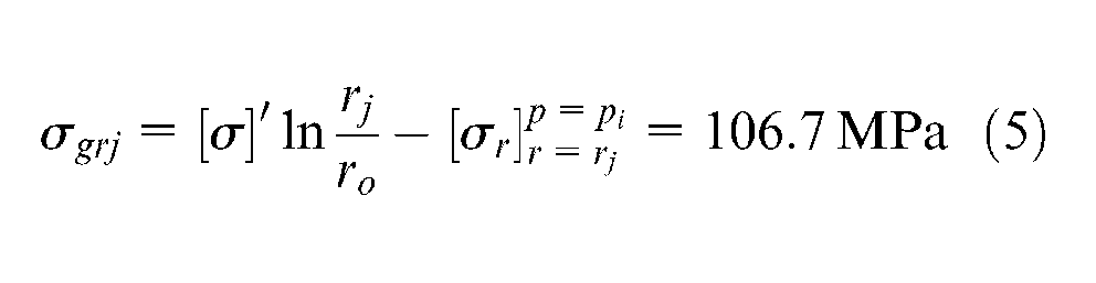
where
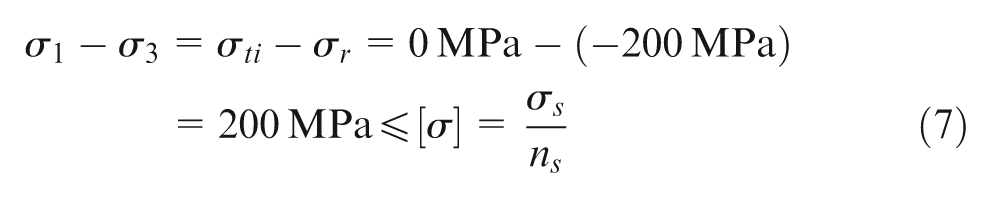
As for the internal surface, which is the dangerous surface, in prestress state after winding
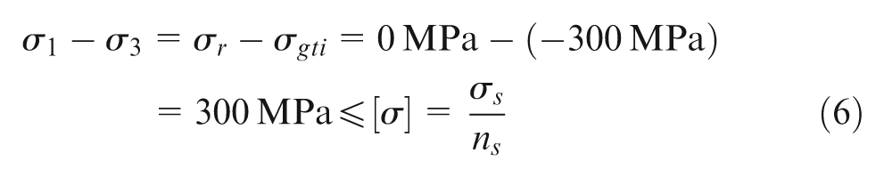
When the internal pressure pi = 200 MPa is loaded on the internal surface
As for commonly used hot-working die steel such as H13, the yield stress is around 1280 MPa at 500 °C. As a result, the internal layer can satisfy the strength criteria for both states and will not fail due to plastic deformation.
A thin cylinder might fail due to structure instability as a result of the external pressure; thus, there is a minimum thickness for the internal layer. The maximum external pressure that the internal cylinder could afford is
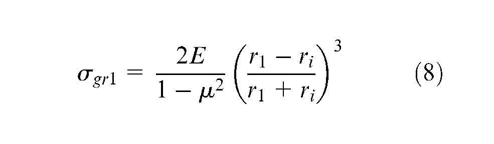
where σgr1 is the external pressure that acts on the internal cylinder and can be computed by σgrj and Lame’s equation. Here, we take the safety factor ns = 2 and it can be computed that r1 = 937 mm. To be more secure, we take r1 = 960 mm and the factual safety factor ns = 3.19.
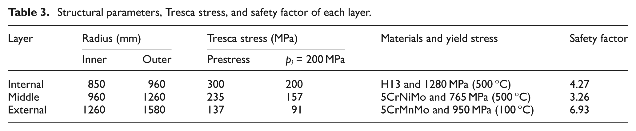
The thickness of the middle cylinder can be determined in the same way as the internal cylinder. It can be computed that the outer radius of the middle cylinder r2≥ 1060 mm. As for the design proposed in this article (see section “Description of the design”), r2 is taken as 1260 mm since there are heating rods inserted in the middle cylinder. The structural parameters, Tresca stress, materials, yield stress, and safety factor of each layer are listed in Table 3. It can be seen that the safety factor is 4.27, 3.26, and 6.93 for the three layers, respectively.
Structural parameters, Tresca stress, and safety factor of each layer.
Function requirements
The function requirements of steel wire wound extrusion containers include the following.
Preheating
Since the extrusion container should be preheated to over 350 °C, measures are required to preheat the container. The simplest way to accomplish this is to put a hot billet inside the container before extrusion, which preheats the container. However, this would lead to remarkable temperature difference throughout the container. The temperature at the internal surface is the highest and decreases dramatically along the radial direction. The uneven temperature distribution would cause great thermal stress, which has been verified by previous research. 1 Another approach is to insert a number of electrical heating rods in the holes drilled in the middle cylinder. In this manner, the temperature of the container is more evenly distributed, and thermal stress can be greatly reduced. In the design proposed in this in this article, the latter one was applied.
Protection of steel wire
It has been mentioned that the temperature of steel wire should not exceed 75 °C, so there must be some measures taken to prevent the temperature rise caused by heat transfer from the hot cylinders to the steel wire.
Prestress distribution throughout the container
There are three types of stress state during the working cycle of extrusion container, as follows:
Prestress state after winding. The container is wrapped up at room temperature, and initial compression stress distribution is generated throughout the container.
Stress state after preheating. The container would be preheated to about 350 °C. The thermal expansion of the container would lead to the increase of tensile stress of the wire and the prestress throughout the container.
Stress state during extrusion process. The internal pressure loaded by the deformed billet is about 200 MPa. This would lead to the changes of stress distribution throughout the container and further increase of tensile stress of the wire.
The control of stress distribution is very important for the design of extrusion container. In our design, we take the prestress coefficient η = 1. This means that there would be no tensile stress when the container is loaded.
Proposed design
Description of the design
Based on the above-described analysis, the following design is proposed (Figure 5). There are a number of heating rods in the middle cylinder and a heat insulation layer between the middle and external cylinders to prevent heat transfer from the heated container to the steel wire. Before extrusion, the heating rods heat the container up to over 350 °C. The temperature distribution throughout the container is shown in Figure 6. Obviously, the temperature of the internal and middle cylinders is much higher than the external cylinder and steel wire. Accordingly, the thermal expansion of the internal and middle layers is also much greater than that of the external cylinder and steel wire. The difference of thermal expansion between the layers could generate contact pressure between them. The contact pressure could provide prestress for the internal and middle cylinders. The external cylinder is prestressed by the steel wire. Therefore, the typical feature of this design is that prestress is generated by the contact pressure due to the differences of thermal expansion. We call this thermally induced prestress. The total prestress is composed of two parts: prestress generated by the steel wire and the thermally induced prestress.
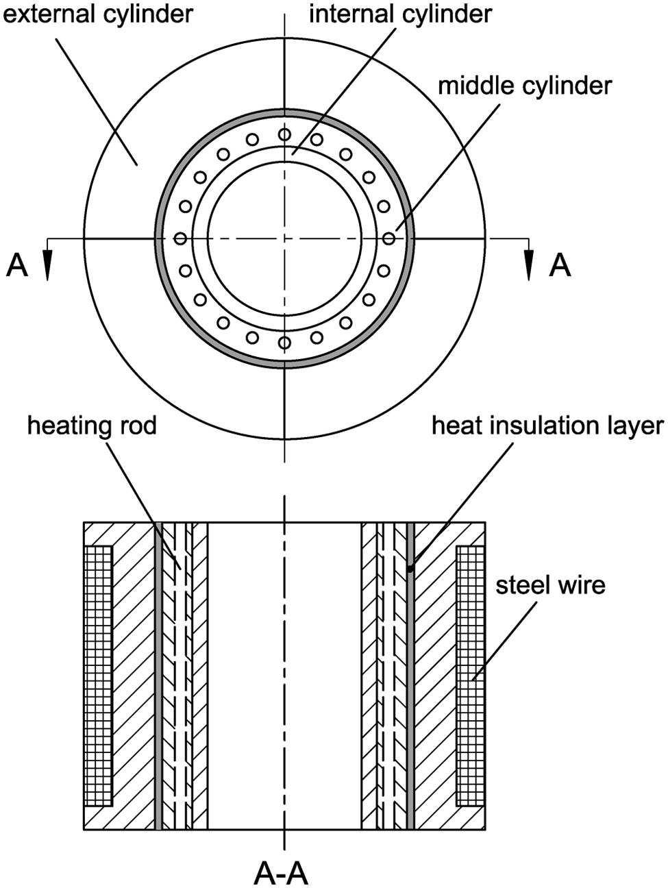
Structure of the container.
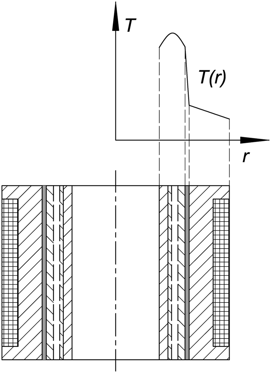
Temperature distribution along the radial direction.
Design variables
To achieve the goal of η = 1, the required contact pressure between the insulation layer and the middle cylinder pk can be computed using Lame’s equation (Figure 7)
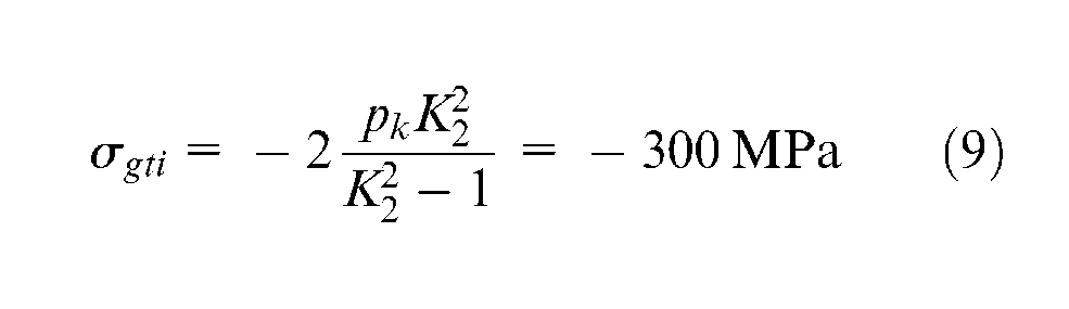
Thus, pk = 81.74 MPa. The factors that might influence the contact pressure between the heat insulation layer and middle cylinder include the following:
Preheating temperature of the internal and middle cylinders. The higher the preheating temperature, the higher the contact pressure. Therefore, the prestress would also be greater.
Properties of the insulation materials. The insulation layer transfers the prestress from the external cylinder to the internal and middle cylinders. If the insulation material is soft and easily deformed, the degree of thermal expansion would not provide the required contact pressure necessary to prestress the container (pk≥ 81.74 MPa). Thus, it is important to carefully select the insulation materials in order to meet this goal.
Contact pressure to generate prestress.
Heat insulation layer
To meet both the mechanical and heat insulation functions, the properties of the insulation materials must include the following:
A low thermal conductivity.
A thermal insulation layer with sufficient rigidity and recoverable deformation (otherwise, prestress will be compromised.)
A thermal insulation layer with sufficient compression strength (greater than 150 MPa).
In the proposed design, a composite material consisting of a mica sheet and a high temperature adhesive was considered. The thermal conductivity of this combination is 0.35 W/m °C. The compression strength is 400 MPa at room temperature, as shown in Figure 8(a) and (b). Repeated load and unload cycles were carried out to observe the deformation behavior of the material (Figure 8(c)). The results showed that the material’s deformation can recover after being compressed one time. Moreover, the compression strengths at 250 °C, 350 °C, and 450 °C were also measured (Figure 8(d)). The strength at 450 °C was 249 MPa, which could fulfill the requirements.
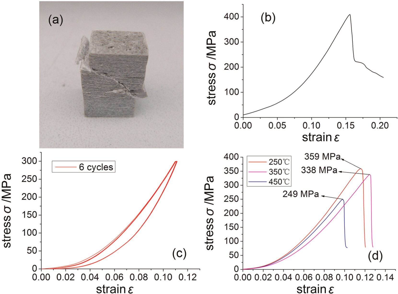
Properties of the heat insulation material.
The constitutive relation of stress and strain was obtained by curve fitting. The model can be characterized by polynomial equations
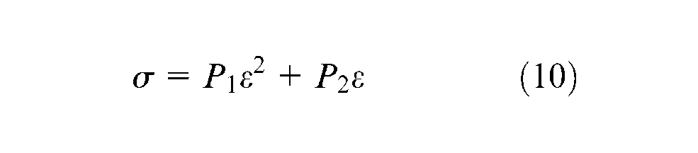
where P1 = −239.04 and P2 = 21276.75. The fitting correlation coefficient is 99.98%. This model can be used to perform numerical simulations.
The problem with the proposed material is its poor machinability. As a result, it is difficult to fabricate a ring-like thermal insulation layer. Consequently, the shape of the selected thermal insulation layer varied from the ideal, as shown in Figure 9. It is composed of three layers of material including the inner plate, the thermal insulation material, and the outer plate. Both the inner plate and outer plate are composed of steel. The insulation material was processed into trapezoid shape. The entire structure is divided into a few pieces, and together, these pieces comprised a ring-shaped thermal insulation layer.
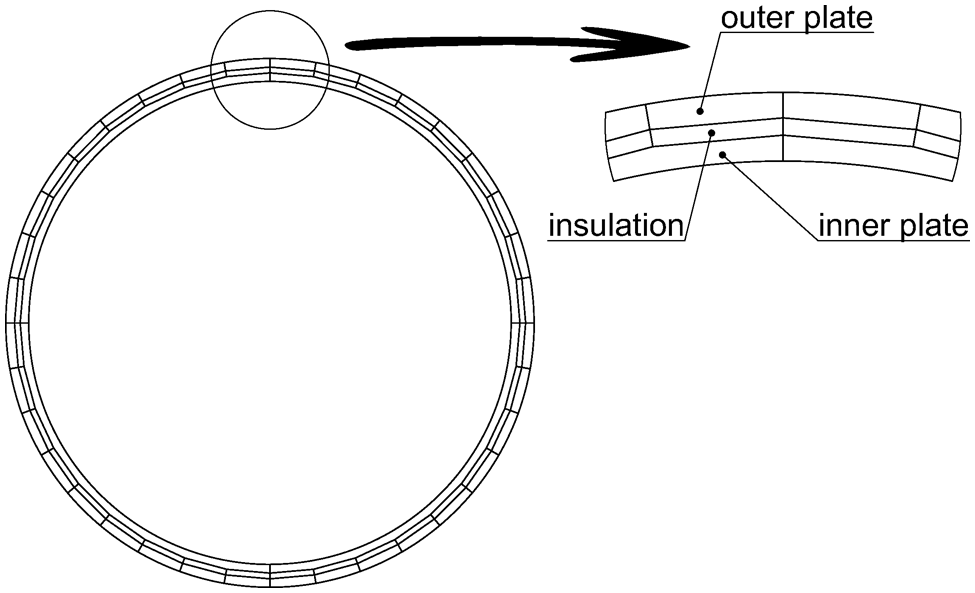
Design of the heat insulation layer.
Proof-of-concept prototype model
Description of the prototype model
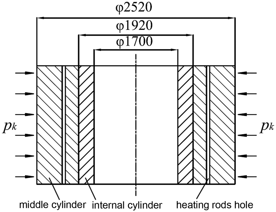
To verify the proposed design, a proof-of-concept prototype of the container was prepared, as shown in Figure 10. Since it is very expensive to fabricate an extrusion container with the diameter of 1700 mm, a proof-of-concept prototype model with the internal diameter of 170 mm was fabricated. The dimensions of the prototype are shown in Figure 11. Our proof of concept primarily focuses on two aspects: the effectiveness of the thermal insulation layer and the concept of thermally induced prestress.
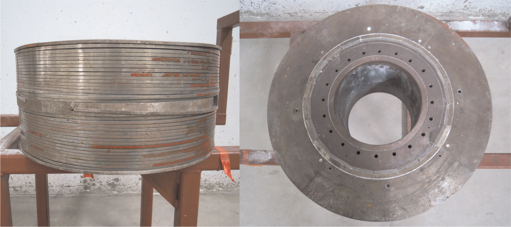
Prototype of the container.
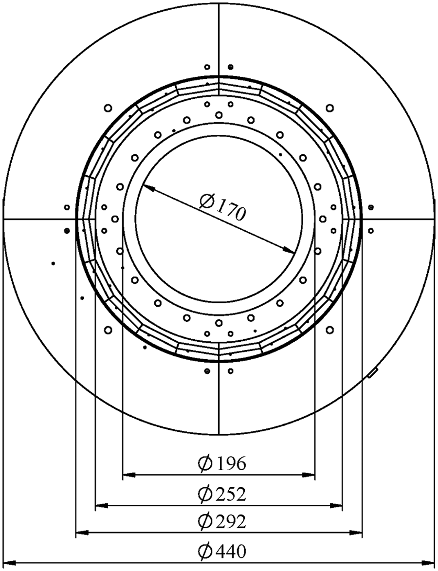
Dimensions of the prototype.
Temperature distribution
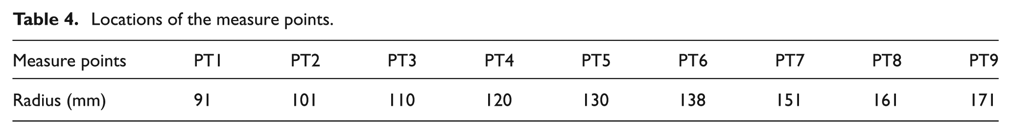
To measure the temperature distribution along the radial direction throughout the container, nine holes were drilled and thermocouples were inserted to the holes. The location of the nine measuring points is shown in Figure 12 and displayed in Table 4. The temperature variation was recorded and transmitted to a computer by a multichannel temperature detecting instrument. The temperature distribution at different preheating times is shown in Figure 13.
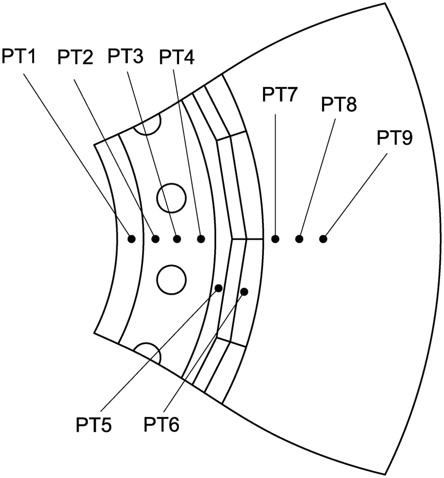
Location of the measure points.
Locations of the measure points.
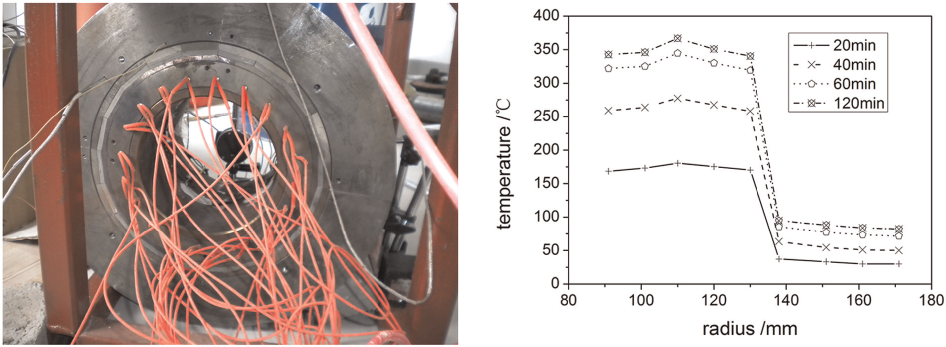
Temperature measurement and distribution along radial direction.
It can be seen that the temperature of the container increased as time elapsed. There was a large temperature difference between the two sides of thermal insulation layer. The temperature of the measurement points of the internal and middle cylinders was much higher than the temperature of the measurement points of the external cylinder. As time elapsed, the temperature distribution gradually reached steady state (after preheating for more than 2 h). The temperature of internal and middle cylinders ranged between 340 °C and 370 °C while the temperature of external cylinder ranged between 82.1 °C and 94.7 °C after preheating the container. Since it is difficult to measure the temperature of the steel wire, we measured the surface temperature of the wire using an infrared thermometer. It was found that the surface temperature of the wire was approximately 50 °C. As a result, it can be inferred that the temperature of the wire ranged between 50 °C and 80 °C. To be more secure, the groove for steel wire was covered by an asbestos cloth with a thickness of 3 mm before wire winding in the event that the temperature of the wire might exceed the 80 °C. The asbestos layer would not influence the temperature and prestress measurement.
Prestress measurement
As mentioned previously, prestress is characterized by σgti. The value of σgti at the middle of the internal surface along the length of the container was measured. To get σgti, both the axial strain εz and tangential strain εt at the internal surface must be measured.
According to the generalized Hooke’s law
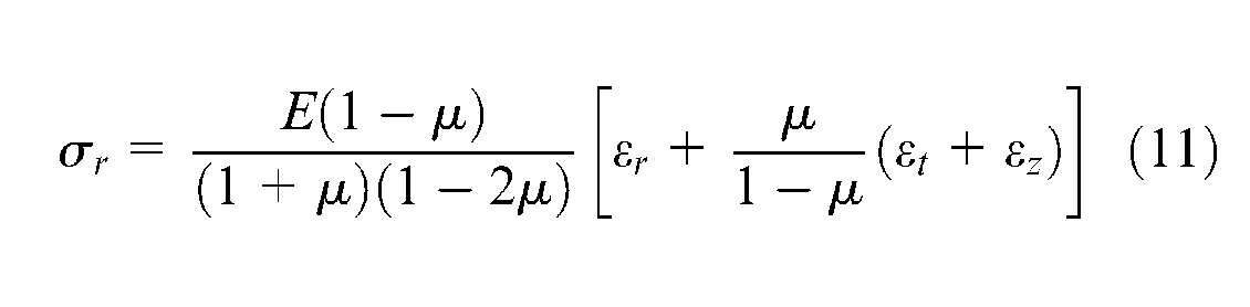
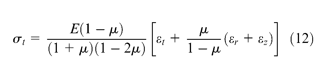
Since the radial stress σr is 0 at the internal surface of the container
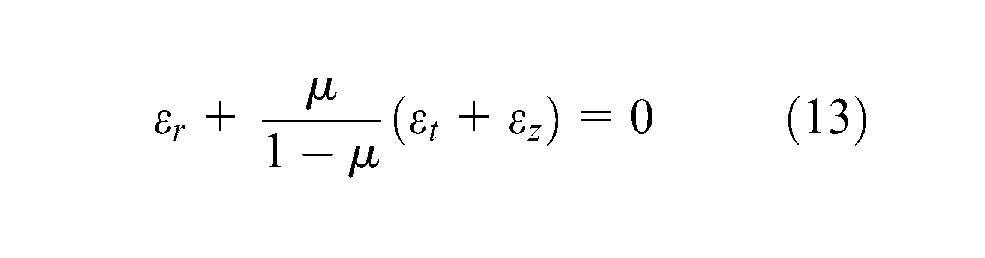
By combing the above equations
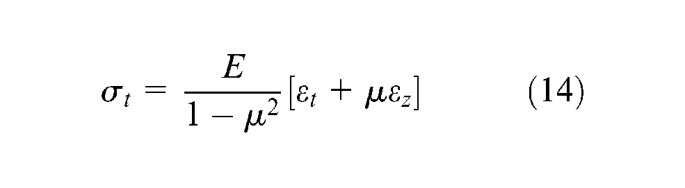
Prestress after wire winding
The container was wrapped at room temperature, and initial prestress distribution was generated. The values measured were εt = −298 µε and εz = 53 µε. The computed tangential stress was σt = −65.1 MPa.
Thermally induced prestress
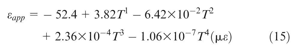
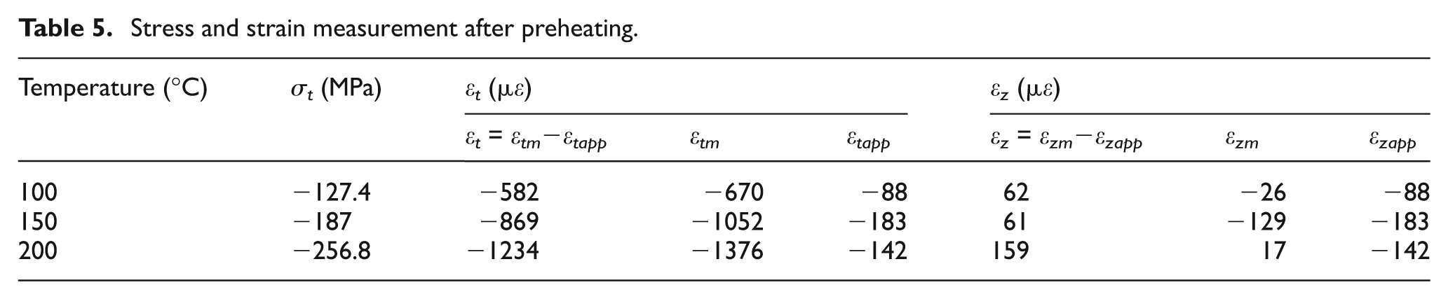
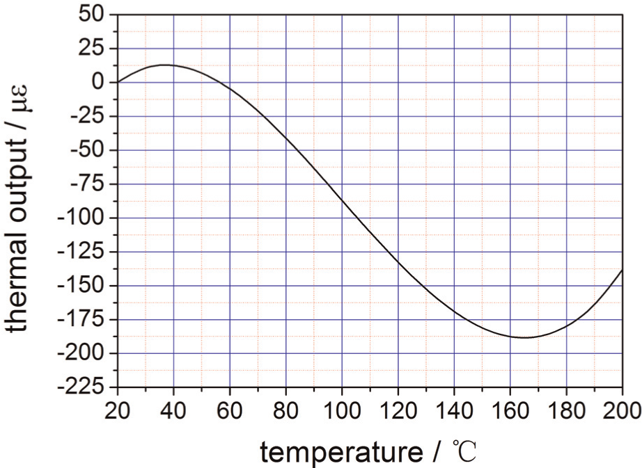
High temperature strain gauge produced by TML Company (Nishitomida, Honjo-shi, Japan) was used to measure strain at elevated temperatures. The results are listed in Table 5. εtm is the value of measured tangential strain and εtapp is the thermal output of the strain gauge. The value of real tangential strain was εt = εtm−εtapp. This was the same for axial strain εz. The thermal output of the strain gauge can be characterized by a polynomial function reported by TML Company, and its variation with temperature is shown in Figure 14. It can be seen that the value of thermal output at 150 °C (−183 µε) is lower than the thermal output at 100 °C (−88 µε) and 200 °C (−142 µε), as listed in columns 5 and 8 in Table 4. The value of real tangential strain decreased from −298 µε at room temperature to −1234 µε at 200 °C, which indicates that the prestress increased with the rise of temperature. The value of measured axial strain at 150 °C (−129 µε) is lower than the measured value at 100 °C (−26 µε) and 200 °C (17 µε). The values of real axial strain at room temperature (53 µε), 100 °C (62 µε), and at 150 °C (61 µε) are very close; however, the value at 200 °C (159 µε) is much higher. This may result from the change of temperature distribution
Stress and strain measurement after preheating.
Thermal output of strain gauge.
Prestress variation with preheating temperature is shown in Figure 15. The initial tangential prestress generated following steel wire winding was −65.1 MPa, and with the increase of preheating temperature, the tangential prestress increased to −400 MPa at 350 °C. The increase of prestress (from −65.1 to −400 MPa) was caused by the difference in thermal expansion between the internal, middle, and external cylinders and steel wire. It can be seen that thermally induced prestress contributed greatly to the total prestress.
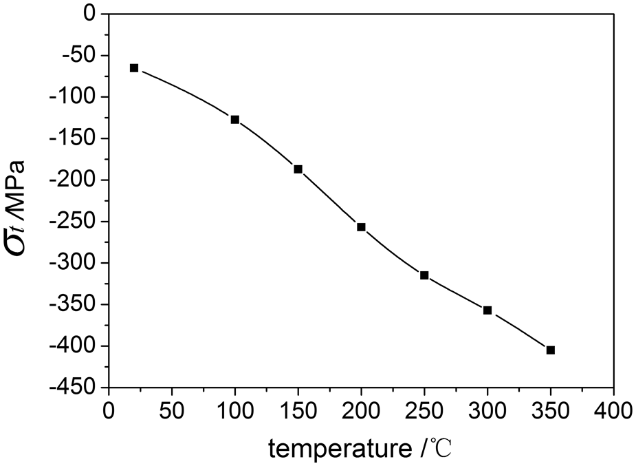
Prestress variation with preheating temperature.
Conclusions and remarks
A novel design for extrusion container is proposed. The container is composed of the internal cylinder, middle cylinder, heat insulation layer, external cylinder, and steel wire. Prestress is generated in two ways: steel wire–induced prestress and thermally induced prestress. Thermally induced prestress is caused by the difference of thermal expansion due to temperature differences in the hot internal and middle cylinders and the normal temperature of the outer cylinder and steel wire. Appropriate thermal insulation material that can satisfy specific requirements was studied, and the properties of this material were measured. A proof-of-concept prototype model was fabricated and tested to verify the design. Both temperature and prestress measurement validated the design proposed in this study. The proposed design offers a new concept for an extrusion container as an alternative to conventional designs. However, there are problems remaining to be settled since the shape of the heat insulation layer is complex and not convenient to fabricate. Further research should focus on developing new heat insulation materials that are easier to fabricate into complex shapes but retain the requisite thermal and mechanical properties.
Footnotes
Funding
This study was financially supported by the Kunlun Advanced Manufacturing Technologies Company.
Declaration of conflicting interests
The authors declare that there is no conflict of interest.