
Abstract
In this article, the effect of separation point on metal flows and the behavior of the material in front of the tool face with a rounded-edge tool are experimentally examined. The character of metal flow near the rake face has obvious significance to the partial problems of the surface finish and accuracy. Analysis of variance is used to determine the most significant parameter for the separation point height from the machined surface. As the distance between the separation point and the machined surface increased, the cutting edge radius grew. It is demonstrated through experiments that the edge radius of the cutting tool affects the machining and material flow process.
Introduction
The cutting edge radius and its influence on chip formation have been a research topic in metal cutting for a long time. A perfectly sharp cutting edge of a tool is typically assumed in many existing models of chip formation developed for machining. 1 It is known that sharp tools are not suitable for machining operations. Because no tool is perfectly sharp, a corresponding force is said to act on the cutting edge. The radius of curvature of the cutting edge has been estimated as of the order of 0.007 mm. 2 Available cutting tools have a tool edge radius varying from 5 to 250 µm. The effect of the edge radius on machining was investigated by Connolly and Rubenstein 3 and Nakayama and Tamura. 4 A stable stagnation zone was accepted to exist when cutting with negative rake angle and rounded-edge tools. Sarwar and Thompson 5 studied the action of a cutting tool with large rounded edge. Abdelmoneim and Scrutton 6 observed a stable buildup in the machining of zinc at very low ratio of uncut chip thickness to edge radius.
Two approaches have been used to model the mechanics of cutting in the stagnant metal zone. The first approach takes a stable buildup of material in front of the tool edge, which diverts material flow. 7 The second approach is based on the subsistence of a separation point on the rounded-edge tool, where the material flow is diverted upward and downward.8,9 Although Waldorf 7 found that the model with stable buildup describes experimental results better, Manjunathaiah and Endres 9 represented equivalent chamfer geometry for the honed tool by using a stagnation point-based approach. Suggested model based on stagnation point assumption successfully captured the effect of edge radius on cutting forces during machining with positive rake angle tools, yet high prediction errors were obtained at negative rake angle cutting conditions.
Enahoro and Oxley 10 denoted that the material flows toward opposite directions around the rounded edge of a tool. Kita et al. 11 studied the flow lines of the metal in front of the rake face with negative rake angle cutting tools. They investigated the deformation process of the material by combining a finite element method with grid line method. Palmer and Yeo 12 prepared blunt tools to obtain an indication of the possible character of the flow. They supported the idea of a stagnation region, which is stationary relative to the tip of the tool. The influence of the cutting speed on the shape of the stagnant region of the material produced ahead of the tool face was investigated. 13 Fang and Zhang 14 reported that the tool edge radius causes an extreme negative rake angle in machining and that the plastic deformation and plowing become dominant action rather than cutting. Abebe 15 investigated the effect of the stagnant region, and this region separated the flow of the workpiece metal into a chip.
During machining, material ahead of the tool is subjected to inordinate deformation that leads to plastic flow. Plastic flow is composed due to the friction between the tool flank and the machined surface. Experimental observation that a relatively stagnant region ahead of the tool divides the plastic flow into upward and downward directions over the tool face is considered in the past studies.12,13,16
In order to understand the chip formation, Komanduri 16 investigated the flow of material on the tool face with negative rake tools. It was reported that the flow of material will be in two directions, with a separation point, which depends on the rake angle.
The possibility of metal flow around a blunt tool is discussed from a theoretical point of view for a material of variable flow stress by Palmer and Yeo. 12 They assumed that all materials that were originally above the level of the cut surface will be reduced in the chip and that all materials that were originally below the level of the cut surface will remain as part of the work.
Kıta et al. 13 obtained the flow lines of material and the deformed region ahead of tool faces and compared them with each other. They reported that material shows, respectively, upward and downward flow on the ahead of the tool face. Also this area belongs to the stagnant region, where flow speed is very slow compared with other parts of the material.
Fang 17 performed a detailed slip-line field analysis for rounded-edge tools based on stagnation point assumption. The slip-line model of Fang 8 has been extended the model of Lee and Shaffer. 18 The stagnation zone in the model decreased with the increasing cutting speed. Later, Fang and Fang 19 presented an analytical model of the chip formation for machining with a rounded-edge tool. In their study, the angle determined the position of the stagnation point on the rounded-edge tool was constant. Woon et al. 20 defined that the stagnation point on the cutting edge remains stationary at all experimental uncut chip thickness values ranging from 2 to 20 µm. Nevertheless, it is also possible to consider this zone as dead metal zone by investigating the velocity profiles given in the study. In spite of these works, the deformation of a stable dead metal zone and flow of the material are not well understood. Very little is in fact known about the type of flow near the tool point.
The goal of this study is to determine the location of the separation point and compose a formula of the separation angle by the experimental studies. Orthogonal cutting experiments are conducted with various rounded-edge tools. Separation point is measured under various cutting speed and rounded edge. Effects of the separation point on the flows of the material and dead metal zone are investigated. The understanding of this phenomenon is important to determine the cutting mechanism of the machining.
Experimental works
Experimental setup
In machining, the material ahead of the cutting tool is deformed first in the primary shear zone and subsequently in the secondary shear zone. A quick stop device helped to investigate the plastic deformation in these zones. This design is a planning-based machining device. There are two basic motions in the device designed for this work: one of them is cutting and the other is sensitive depth cut motions. Control of the device is provided by a servo motor and a driver. The drive applies power to the motor at frequencies that are varied by the user. The motor speed is a result of the output frequency of the drive and slip due to the mechanical load. The maximum thickness and width of the chip that can be machined by the device are 2 and 1.5 mm, respectively. The designed device may be operated at the maximum cutting speed of 17.5 m/min. Cutting speed is determined whereby the software installed in the computer. As well cutting forces can be measured by the quick stop device with the help of the strain gage and strain gage indicator during machining. The cutting process is stopped suddenly by changing the relative velocity between workpiece and tool to zero. The photograph of the quick stop device is shown in Figure 1. Quick stop device is designed and manufactured for this work.21,22
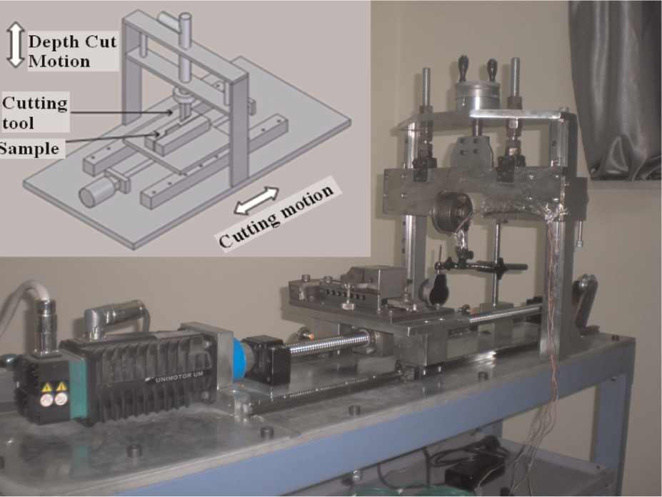
Quick stop device. 21
Experimental procedure
The material used in this study was brass, CuZn30, because dead metal region generated during machining with brass and built-up edge did not existed. 23 The hardness was measured to be 70 HV. The tests were carried out on specimens with 32 mm × 30 mm × 1.5 mm that were manufactured from the supplied material. Planning was performed using cutting inserts with cutting edge radii of about 50, 100, and 150 µm. The radii were very carefully measured and showed considerable variability from edge to edge. Measurements were performed using the white light interferometry-based instrument. All the inserts had a clearance angle of approximately 11°. The cutting inserts are secured to the tool holder. Cutting tools used in machining must maintain functionality throughout the material removal process to ensure minimal cutting forces.
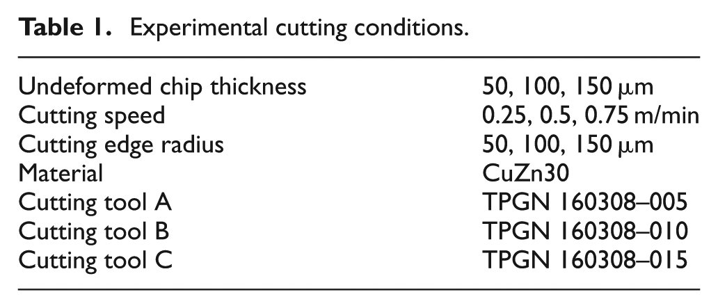
The purpose of experimental work was to observe the nature of flow around the tool point during orthogonal cutting with a continuous chip. Cutting was performed by a quick stop device to give a planning action. Temperature effects were negligible in the metal cutting due to low cutting speeds. Chatter did not occur during these tests. The data sets used in this study were reported in Table 1. Before the cutting process, cutting speed and stopping distance of the device can be adjusted with PLC (Programmable Logic Controller) program. Each tool cutting edge was used for once.
Experimental cutting conditions.
A summary of the experimental procedure can be described as follows: (1) cutting with planning-based quick stop device, (2) freezing the cutting action, (3) grinding and polishing of the mounted specimen, (4) etching, and (5) examination of the workpiece using optical microscopy.
Results and discussion
Position of the separation point
To explain the mechanism of chip formation, the behavior of material ahead of a tool face was examined with rounded-edge tools. Quick stop was practiced by freezing the cutting process in cutting speeds up to 0.75 m/min.
Cutting tests were performed on brass with a wide range of edge radius. After freezing the cutting action, the chip remains attached to the workpiece. Each testpiece was mounted, polished, and etched, and the optical microscopy allows images to be taken of the tool point. The workpiece material forming the chip should leave with the right velocity distribution to give the chip curvature. Dead metal zone can be clearly seen in the photomicrograph of cutting zone. It should not be confused with the built-up edge. A built-up edge actually changes the tool geometry and can be regarded as desirable in metal cutting if it is small in size and stable, since it protects the rake face as well as the tool tip in that case. In this study, an unstable stagnated region was noticed that changed in shape during cutting with a rounded-edge tool.
When a rounded-edge cutting tool is used during the experiments, the main particular node on the rounded edge to separate is a big question. The separation point is where the workpiece material starts to split into two parts, one forming the chip and the other forming the new surface. This separation point varies with cutting conditions. Slow-speed cutting tests were executed to study the action of rounded-edge tool on the geometry of the orthogonal cutting process. This will help clarify the location of the separation point. The identification of the separation point K on the edge radius of the cutting tool was discoursed in this section. Chip formation is continuous with no built-up edge as illustrated in Figure 2. K is the separation point as seen in the schematic diagram of the chip geometry. In Figure 2, r is the edge radius of the cutting tool. The thickness of material to be removed is the uncut chip thickness “t.” Height of the separation point from the machined surface was denoted by “a” in Figure 2. Separation angle “ξ,” in Figure 2 depends on the edge radius r and uncut chip thickness h and defines the separation point.
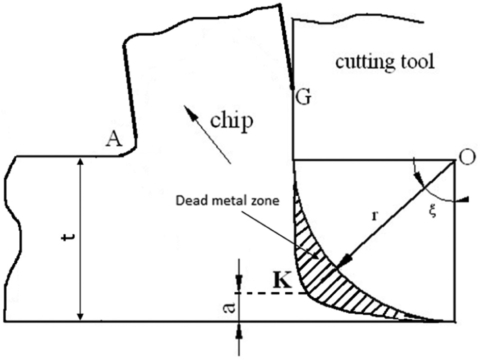
Schematic diagram of the dead metal zone and chip geometry for machining with a rounded-edge tool
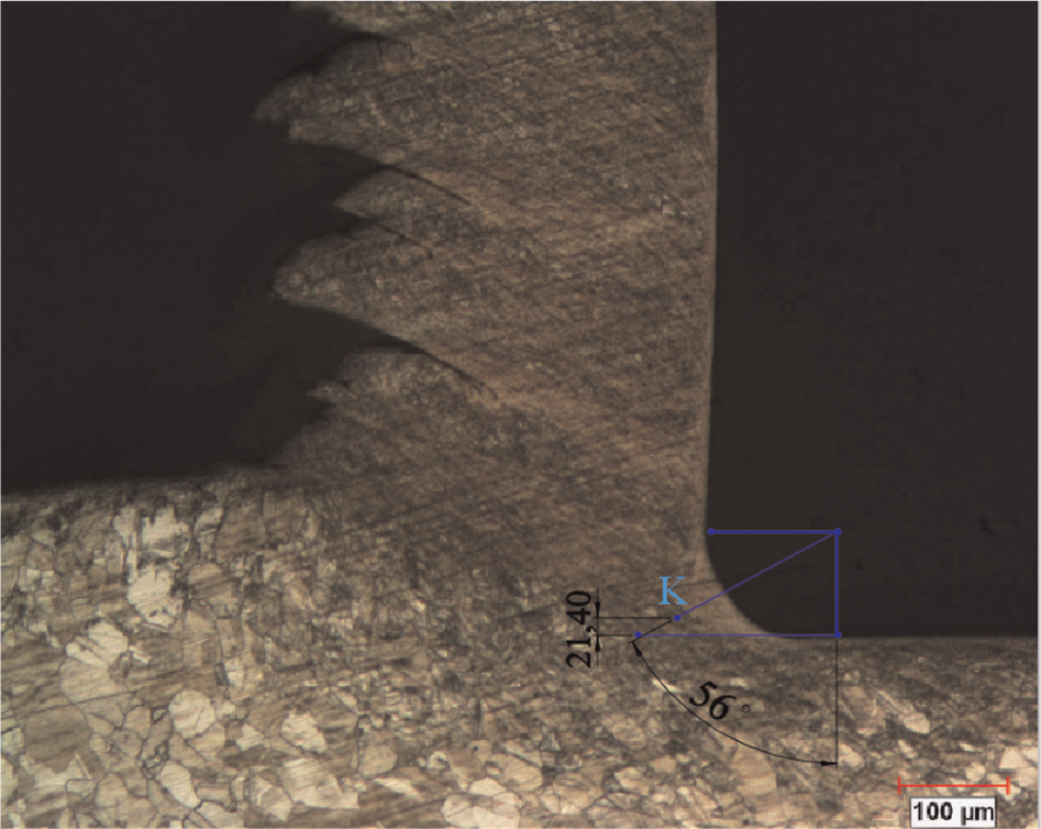
Photomicrographs of chip roots obtained at various rounded edge and uncut chip thickness are shown in Figures 3–5. Shear plane separating the deformed and undeformed regions is seen clearly in these figures. The first step in this approach would be to conduct detailed experimental work to assess the behavior of the material under these influencing factors. Figures 3–5 demonstrate the separation point position on the tool tip at the same cutting velocity. In the beginning of cutting process, the stagnation zone started to form, and then its size stabilized when steady state cutting was reached. Figures 3–5 show the existence of the stagnation point K above which the material flows into the chip and below which it flows back into the work. This stagnation point would be a point at which the material flow velocity is zero. The figures show the deformation zone observed while cutting with tools having different cutting edge radii.
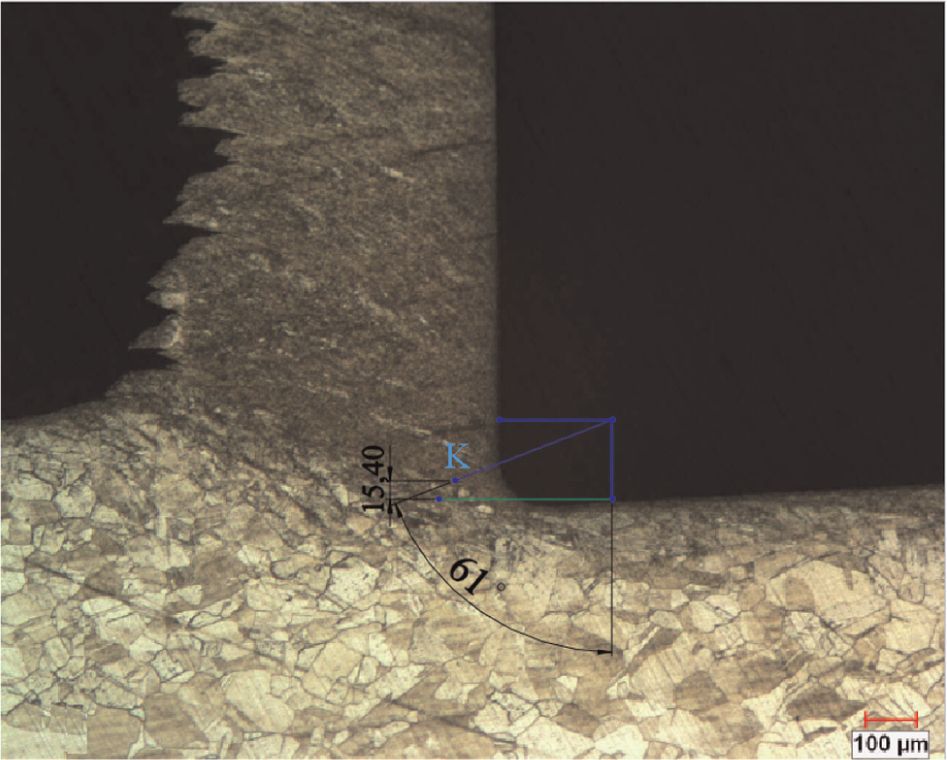
The position of the separation point at 100× magnification (γ = 0°, r = 50 µm, v = 0.5 m/min, t = 100 µm).
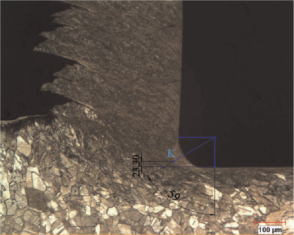
The position of the separation point at 100× magnification (γ = 0°, r = 100 µm, v = 0.5 m/min, t = 100 µm).
The position of the separation point at 100× magnification (γ = 0°, r = 100 µm, v = 0.5 m/min, t = 50 µm).
Visually observed location of separation point from the images is measured by the help of the Solid Edge software. In all cases, a dead metal zone is observed. Material should leave the plastic zone with the velocity of the workpiece if it is to remain as part of the workpiece. The position of the separation point is defined by the separation point angle ξ, which measures the angular displacement of the separation point to the vector of undeformed chip thickness. The separation point angle as determined from the experimental photomicrographs is illustrated in Figures 3–5. Height (a) for different cases that experienced stagnation zone formation is measured with the photomicrograph as shown in Figures 3–5. Moreover, in these images, value of “a” (in millimeters) is determined at 100× magnification.
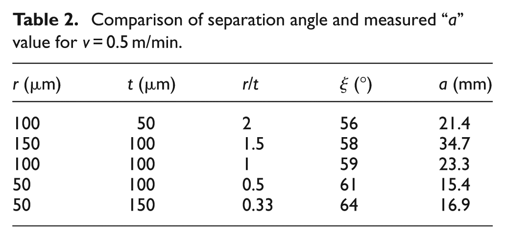
The cutting conditions and experimental results are summarized for v = 0.5 m/min in Table 2. Table 2 shows a variation of r/t ratio with respect to separation angle and “a” value. A clear linear relation between the size of stagnation zone and tool edge radius may be seen from this work. Experimental results confirmed that as r/t ratio decreases, separation angle increases. The value of separation angle varies from 56° to 64° as illustrated in Table 2. As the cutting edge radius decreases, the location of the separation point is found to be closer to the machined surface.
Comparison of separation angle and measured “a” value for v = 0.5 m/min.
As expected, this present work considers the existence of stagnated metal zone. It is clear from these images that stagnation zone increases as the edge radius increases at the constant cutting speed. This increasing has been attributed to different reasons such as the enlargement of plastic deformation zone as edge radius decreases. With the help of these images, a new model can be composed for cutting with rounded-edge tool.
Material above the separation point on the dead metal zone is separated from the chips while material belonging underneath the separation point is compressed by the rounded-edge cutting tool. A material below the separation point flows underneath the tool along the flank face, and a work material above the separation point begins to flow along the rake face and becomes the chip. As material passes under the tool, it will recover elastically and will be in contact with the flank surface. All materials above the stagnant point move parallel to the rake face. A part of the material moving along the flow line near the tool tip actually flows upward and turns toward the separation point and subsequently flows downward under the tool and becomes part of the newly machined surface.
In this article, tests were performed at low cutting speeds, and the study mainly focused on the effects of the stagnation point. However, it appears that the formation of the chip in these speeds similar to formation in the actual cutting speed used in industrial environments. The clear images of the stagnation zone are the further proof of this conjecture. Nevertheless, future experiments will be conducted on high speeds in an attempt to see effect of the stagnation zone.
Subsequently, stagnant dead metal zone covers greater range of the tool tip in all cutting cases as shown in Figures 3–5. The flow of material on the tool face is separated in two directions—some under the tool and some up the tool face from a chip, with a separation point. This task is correctly modeled the stagnation zone phenomenon in a way that matched the experimental results found in the literature.
In the past studies, separation point was identified without experimental works.20,24 It is clear that there are no perfect methods to reliably predict separation point when cutting with edge radiused tools. The issue of the “stagnation point” produced under certain conditions in machining processes is also studied. In the previous works, height of the separation point from the machined surface was never measured and determined with experimental images. Jin and Altintas 24 used finite element analysis software ABAQUS/Explicit v6.8. and considered a constant separation angle of 56° in the slip-line field model for turning brass with the Carbide tool with an edge radius of 20 µm. In their study, the variation of the separation angle was found to be less than ±1°. Simulation results of Woon et al. 20 showed that the stagnation angle at the tool round edge was in the range of 58.5 ± 0.5°. However, in the present study, the value of separation angle varies from 56° to 64°. The observation does not support the view of variation of the separation angle only in the range of ±1°. From the experimental studies, separation angle was changed in the range of 60±4°. Moreover, separation angle produced at different r/t ratio is shown in Table 2. It implies that the edge radius creates favorable conditions for the separation angle, which is in accordance with the findings of Woon et al. 20 and Jin and Altintas. 24
Analysis of the results
Analysis of variance
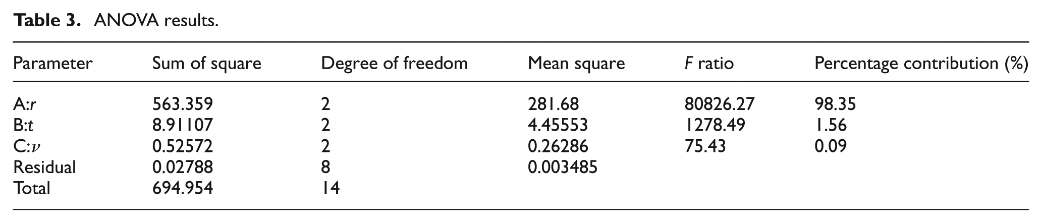
Cutting edge radius was found to be the most significant parameter for separation point height from the machined surface by analysis of variance (ANOVA) as given in Table 3. It can be clearly seen from Table 3 that cutting edge radius is the most important parameter with a contribution ratio of 98.35% on the separation point height from the machined surface. It is obvious from the Table 3 that the contribution ratio of the uncut chip thickness is 1.56%.
ANOVA results.
Multivariable regression analysis
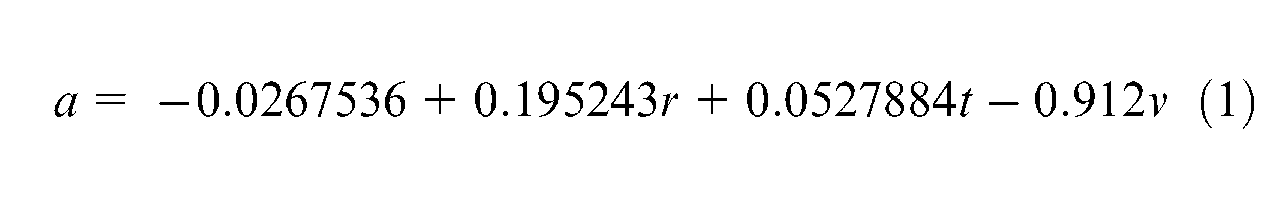
In order to determine the relationship between factors ((1) cutting edge radius r, (2) uncut chip thickness t, and (3) cutting speed v) and the separation point height from the machined surface (a), the multivariable regression analysis was employed. Multivariable linear regression analysis results are summarized in Table 4. The output shows the results of fitting a multiple regression model to describe the relationship between “a” and three independent variables. The equation of the fitted model is

Multivariable linear regression analysis.
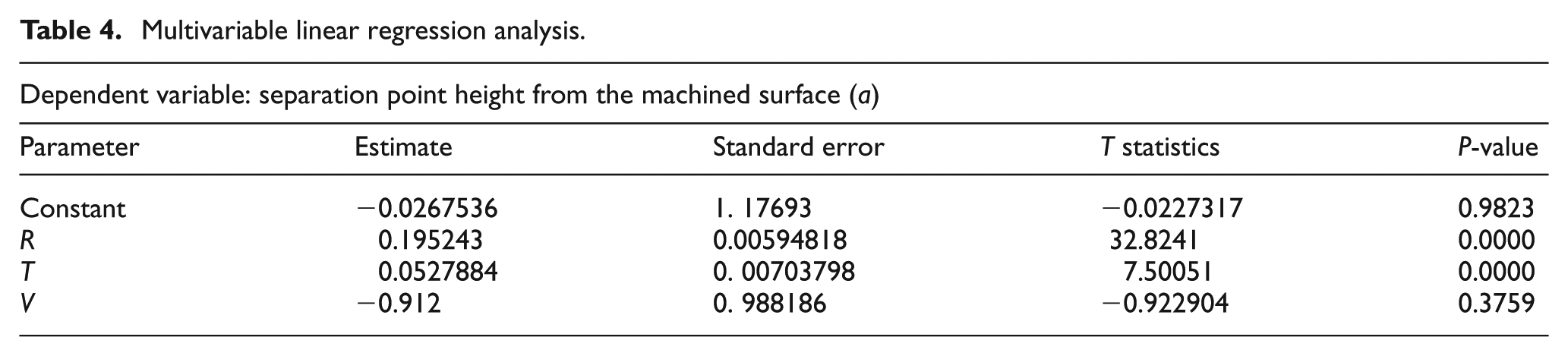
Since the P-value in the ANOVA table is less than 0.01, there is a statistically significant relationship between the variables at the 99% confidence level. The R-squared statistic indicates that the model as fitted explains 99.034% of the variability in “a.” The adjusted R-squared statistic, which is more suitable for comparing models with different numbers of independent variables, is 98.7705%. The standard error of the estimate shows the standard deviation of the residuals to be 0.781229. The mean absolute error of 0.592986 is the average value of the residuals. The Durbin–Watson (DW) statistic tests the residuals to determine whether there is any significant correlation based on the order in which they occur in our data file. Since the DW value is greater than 1.4, there is probably not any serious autocorrelation in the residuals.
The distance between the separation point and the machined surface can be calculated from equation (1) with necessarily knowing only cutting edge radius, uncut chip thickness, and cutting speed. In addition, both of them must be determined before the cutting. Equation (1) represents a highly successful example of applying the experimental results to the formulating the location of the separation point.
In order to investigate the relationship between the dead metal zone and the cutting speed, separation angle and “a” value are measured for three different cutting speeds. Changes of dead metal zone and separation point are analyzed. Dead metal zone enlarges as the cutting speed decreases. Furthermore, the distance between the separation point and the machined surface decreases parallel to increasing the cutting speed. If the cutting speed changes from 0.5 to 1 m/min, the value of “a” varies only 0.85%. On account of the fact that increasing of this distance is too small, the effect of the cutting speed on the process is negligible. Moreover, in determining whether the model can be simplified, notice that the highest P-value on the independent variables is 0.3759, belonging to v. Since the P-value is greater or equal to 0.10, that term is not statistically significant at the 90% or higher confidence level. Consequently, v should be removed from the model.
Conclusion
In this study, cutting mechanism of the machining with rounded-edge tools and the stagnation zone formation were studied. Finally, the formation of a continuous-type chip, variation of the separation point, and flow of the material were discussed. The objective of this article is to experimentally investigate the effect of edge radius on separation point and flow of the material.
The results obtained in the present study can be summarized as follows:
Photomicrographs of the acceptable results were obtained, indicating that the device served the purpose of providing a research instrument for the study on chip formation.
The distance between the separation point and the machined surface (a) can be calculated from equation (1) with only knowing of tool edge radius (r), uncut chip thickness (t), and cutting speed (v).
ANOVA gave results in determining the percentage contributions of the key factors that the cutting edge radius is the most important parameter with a contribution ratio of 98.35%.
Multivariable regression analysis was also employed to determine the correlations between the factors and the separation point height from the machined surface.
Dead metal zone was determined to be very important with plastic flow in the subsurface layer.
It was demonstrated through experiments that edge radius of the cutting tool affects the machining and material flow process.
Footnotes
Appendix 1
Declaration of conflicting interests
The authors declare that there are no conflicts of interest.
Funding
The authors would like to thank the Yıldız Technical University Scientific Research Projects Coordination Department for the financial funding for this project (No: 25-06-01-02).