
Abstract
Hybrid layered manufacturing, an automatic layered manufacturing process for metallic objects, combines the best features of two well-known and economical processes, namely, weld-deposition and milling. A study of the mechanical properties like hardness and tensile strength of objects made through hybrid layered manufacturing is presented in this article. It was found that the interior matrix has negligible hardness variations in all directions. The tensile strength of the matrix displays negligible variations in the horizontal plane. However, the same for the vertical direction initially was found to be slightly lower, but this could be rectified by increasing the weld-deposition current. The ability of hybrid layered manufacturing to make composite material matrix with good material bonding has also been demonstrated. These studies help in understanding and controlling the anisotropic behavior of objects built using weld-deposition–based rapid prototyping and manufacturing techniques.
Introduction
Decreasing time spans for the development of a new product and their growing complexity have facilitated the growth of rapid manufacturing (RM), also referred as additive manufacturing. Total automation in creating the physical models from the virtual ones is made possible with RM by splitting the computer-aided design (CAD) model into layers and building each layer at a time. Based on the energy source used for metal deposition, varying RM methods can be grouped as those that use laser, electron beam, and electric arc. Being narrow and concentrated energy sources, laser and electron beam have higher accuracy and feature definition over arc. However, arc can offer higher deposition rates and material utilization vis-à-vis laser and electron beam. 1 Due to these reasons, hybrid approaches have evolved as attractive methodology: creation of near-net shape with weld-deposition and using machining to obtain the final geometry.
Three-dimensional (3D) welding was developed at the University of Nottingham for producing complex parts entirely from weld-deposition. 2 In this process, a robot that holds the gas metal arc welding (GMAW) torch does the deposition of material. Shape deposition manufacturing (SDM) is another arc-based deposition process making use of deposition and milling. 3 Unlike the uniform slicing used in 3D welding, it uses very thick segments. Because of its five-axis kinematics and path planning involved, SDM is not a fully automatic process. Direct metal deposition (DMD) developed at Southern Methodist University, USA, is another 3D welding process, which uses gas tungsten arc welding (GTAW) instead of GMAW.4–6 One of the difficulties with GTAW is the need for orienting the nozzle of the wire to match the torch direction, which adds an additional control axis during the deposition. Wu and Kovacevic 7 introduced pulsed-current welding into the GMAW process in order to decouple the metal transfer process from the base plate heating process. It was also observed that additional mechanical force resulting from wire electrode oscillation could make the droplet size smaller and produced a higher droplet transfer rate, thus greatly improving the droplet transfer process in GMAW. Researchers at the Korea Institute of Science and Technology (KIST), South Korea, have also worked in GMAW-based hybrid RM process. In fact, they had mounted on the spindle head of the same computer numerical control (CNC) machine a laser torch and two GMAW torches.8–10 Thus, this platform could be used for both laser and arc deposition studies. Researchers at the University of Kentucky, USA, have developed a dedicated control technology, including slicing/planning, system implementation, and postprocessing using GMAW as the deposition process through an integrated and user-friendly environment. In this system, the deposition parameters, including torch speed, torch inclination, welding current, and arc voltage, are controlled to achieve the required density and 3D geometry.11,12 Microplasma arc welding (MPAW) developed by Aiyiti et al. 13 replaces GMAW with plasma to achieve narrow arc and deposition. Another variant of arc-based deposition process using a plasma arc is hybrid plasma deposition and milling (HPDM). 14 It employs a combination of plasma deposition as an additive and milling as a subtractive process. Although many of these processes use weld-deposition along with machining to achieve the final object, the process planning and control happens separately, hindering computer-aided process planning (CAPP). Arc-based hybrid layered manufacturing (HLM) developed at Indian Institute of Technology (IIT) Bombay gets around these constraints by combining weld-deposition and finish machining into a single machine.
Synchronized integration of CNC machine and weld-deposition unit is one of the key advantages of HLM. It also makes high deposition rates possible.1,15 Figure 1 illustrates the various steps in the HLM process. The first phase comprises manufacturing the near-net shape of the object using weld-deposition and face milling; while weld-deposition is used to create each layer, face milling of the layer ensures uniform layer thickness. The near-net shape thus manufactured is finish machined in the subsequent phase. Weld-deposition is carried out using a “Fronius TransPuls Synergic (TPS) 4000” metal inert gas (MIG) welding system. The tool paths for the area-filling in weld-deposition are generated using custom-built software, namely, Hybrid Layered Manufacturing Software (HLMSoft).
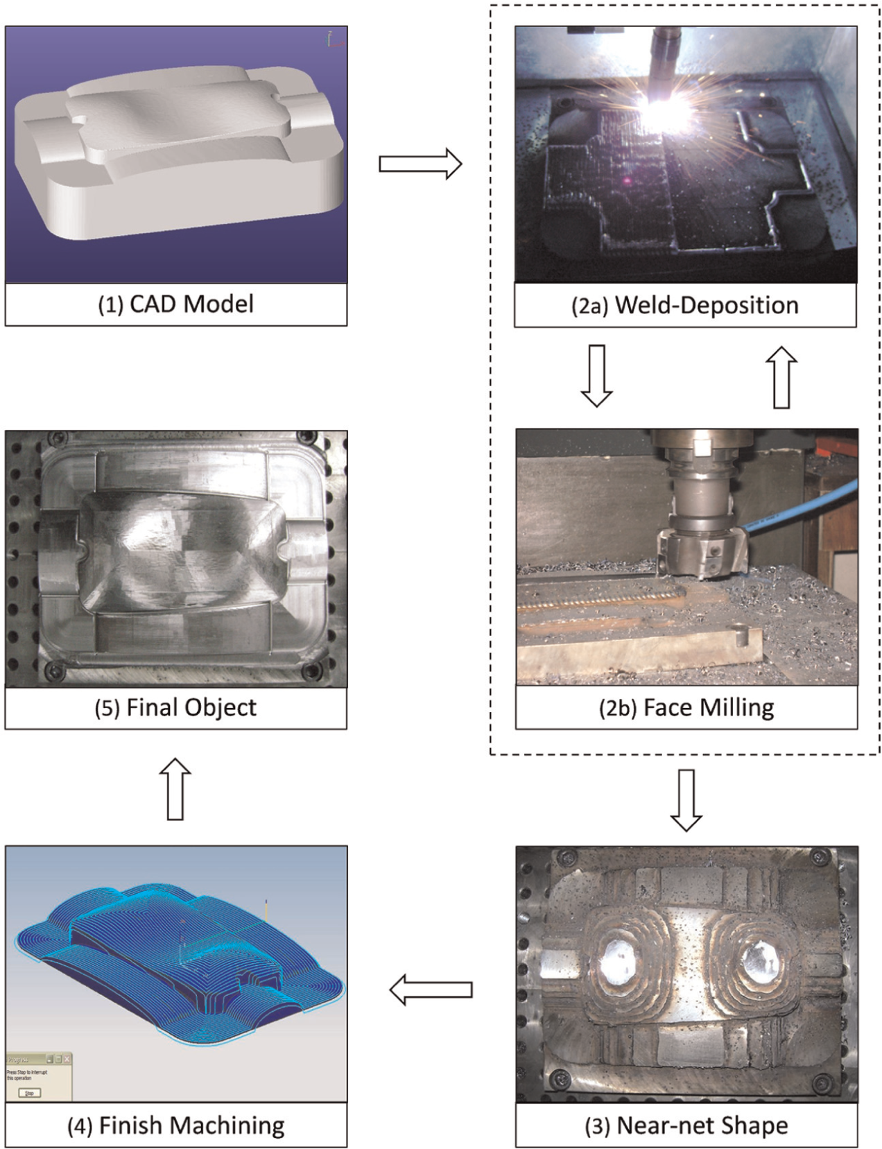
Flow chart for Hybrid Layered Manufacturing (HLM) process.
Evaluation of the HLM vis-à-vis traditional manufacturing approach of CNC in terms of cost and time has been carried out through various case studies at IIT Bombay.1,16 However, similar evaluation in terms of material quality was found lacking. Zhang et al. 17 compared the properties of 663 copper alloy and 316L stainless steel samples made using laser deposition and found that their mechanical properties are equal to or exceed those for casting and wrought annealed materials. Zhang et al. 18 demonstrated that fully dense TiAl alloys can be deposited using laser engineered net shaping (LENS) technology. Similarly, Murr et al. 19 and Li et al. 20 demonstrated the ability of electron beam melting to manufacture functional 18 aerospace and orthopedic objects. Characterization studies for metallic objects made through RM by other researchers too mainly focused on laser and electron beam–based processes. Thus, the analysis of properties of objects made through gas metal arc (GMA) weld-deposition–based HLM process is the focus of this article. The study also aims to control the anisotropic behavior of the deposition, facilitating the creation of functionally gradient materials.
Unlike the subtractive process where the object is carved out of a billet, in HLM, the material is added where required. While the characteristics of a billet are closer to that of a forging, the properties of the HLM object are closer to a casting. In fact, some researchers like Klingbeil et al. 21 refer to this additive method as microcasting. As casting has bulky cross sections and occurs in closed volume, it is prone for filling and solidification defects such as hot spots and cold shut. As HLM is free from these defects, its properties are likely to be better than that of a casting. In other words, it is likely to be between casting and forging. The following properties of the matrix built using HLM are discussed in the subsequent sections:
Hardness,
Tensile strength.
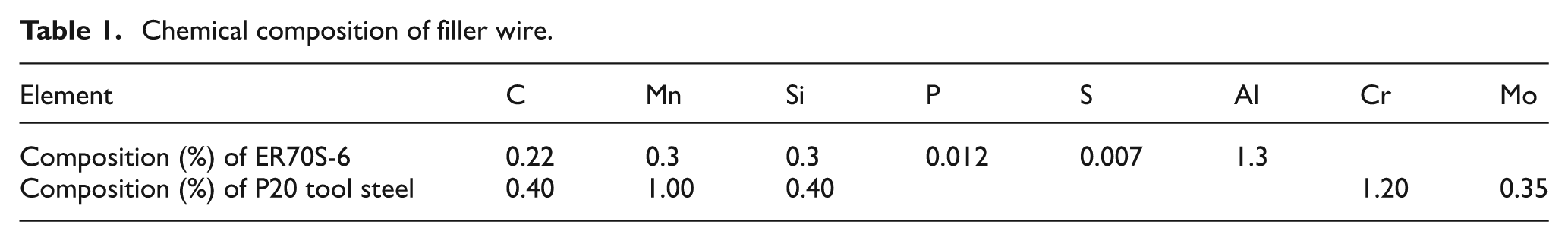
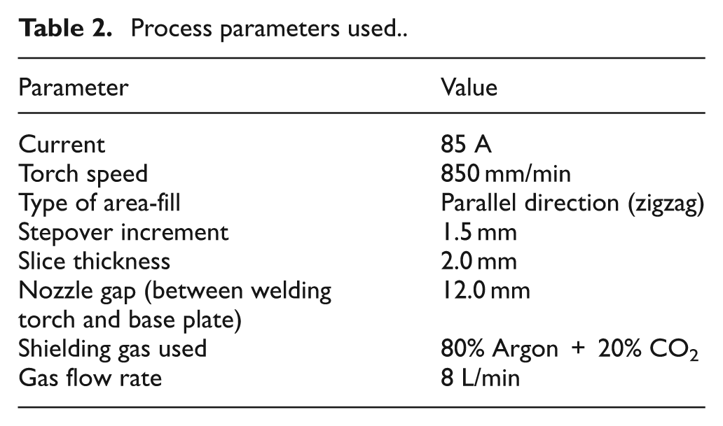
These analyses were done for a copper-coated mild steel filler wire, ER70S-6, of diameter of 0.8 mm. Table 1 lists its chemical composition. Process parameters listed in Table 2 have been used consistently for all the experiments. Subsequently, the ability of HLM to produce composite matrix has also been studied.
Chemical composition of filler wire.
Process parameters used.
Hardness
The life of a die or mold is largely dependent on its surface hardness. Hardness measurement is also used for assessing the tensile strength of components due to their direct correlation.
Methodology
As the object is built in layers in HLM, the lower the layer, more are the thermal cycles it undergoes. In order to understand the effect of thermal cycles on hardness, three specimens with varying number of layers were made (Figure 2) and their hardness variation along build direction (i.e. vertical direction) was studied. Rockwell Hardness B Scale with 1/16″ ball penetrator and a 100 kgf (0.98kN) load were used for the measurements. Automatic Rockwell Tester (LC200RB) manufactured by Future-Tech Corp. and conforming to the American Society for Testing and Materials (ASTM)-E140 was used for the measurements. The error in the hardness readings was calculated by measuring the hardness of the top layer of a specimen at 10 different locations.
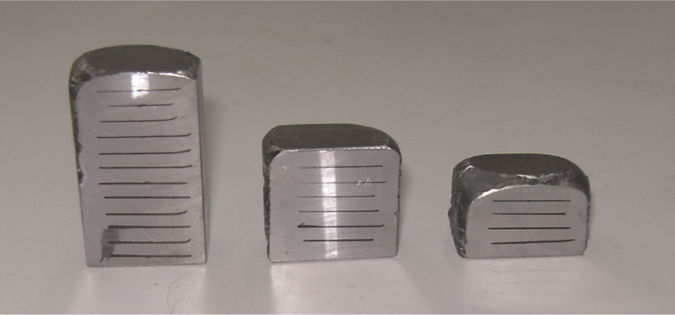
Specimen for testing the hardness variation.
The experimental results were correlated using a simplified model of the deposition process. Thermal analysis of deposition over a simple block was carried out using Fluent software. The top surface was assumed to be at the melting point temperature of the metal, and the bottom surface was maintained at ambient temperature. Convective heat transfer to the atmosphere and conductive heat transfer into the block were assumed.
Experimental results
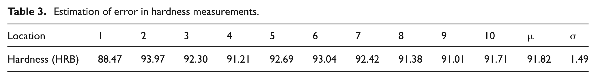
The measured hardness values of the top layer of a specimen are given in Table 3. The error was estimated by calculating the standard deviation of the 10 sample readings. The same error margin was extended to the subsequent hardness measurements. Figure 3 plots the hardness of a layer against the number of thermal cycles it is subjected to (as a result of weld-deposition in subsequent layers). The thermal distribution based on Fluent analysis is shown in Figure 4.
Estimation of error in hardness measurements.
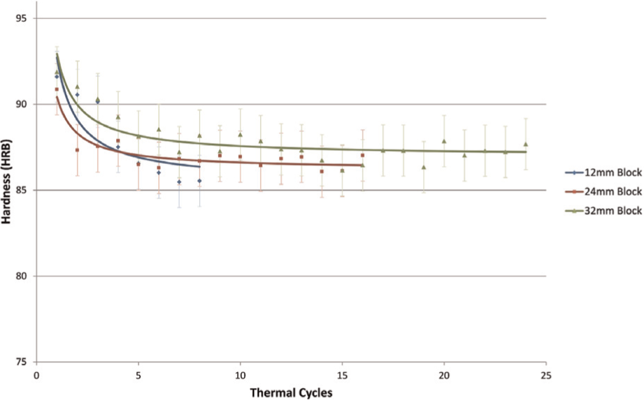
Hardness versus thermal cycles for various heights.
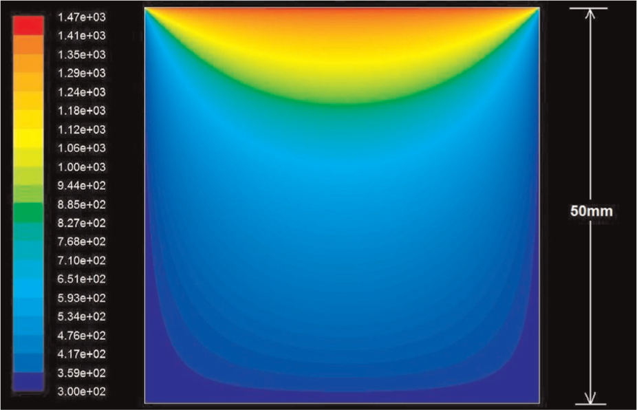
Thermal distribution along vertical plane in a rectangular block.
Discussions
The variation in hardness can be attributed to the number of thermal cycles a given layer undergoes. It was observed that hardness of the material is the highest in the top most layer. It falls rapidly within a first few thermal cycles, about five layers in this case, before stabilizing. In other words, thermal cycles during weld-deposition will have negligible effect on the material properties after around 10 mm/five layers. Figure 5 further elucidates this relationship between layer number and thermal cycles undergone.
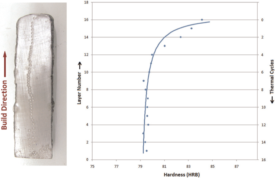
Hardness variation along vertical direction.
As the metal is deposited in layered bottom-up manner in HLM, the latest layer stands on the top. As more and more layers are added, the distance between a given layer and point of heat input increased continuously. In other words, for a given layer, the distance of the current layer (or source of heating) keeps increasing as the deposition progresses (Figure 6). The increase in distance results in decreasing effect of thermal cycle on a given layer. When a given layer is nearer to deposition, it will be at a high temperature, resulting in annealing and softening effects. After some layers (five layers for the chosen set of process parameters), the temperature gradient falls below the recrystallization temperature and thermal cycles cease to have an effect on its hardness. This phenomenon tallies with the experimental observation that hardness variations below 10 mm thickness are negligible. The following are the significant inferences based on the earlier discussions:
The hardness variation exists only in the final layers. It falls rapidly within a thickness of few layers, about five layers in this case. In other words, the interior matrix has negligible hardness variation.
The hardness of the core is independent of the number of thermal cycles, irrespective of whether all the layers are deposited continuously or with breaks in between.
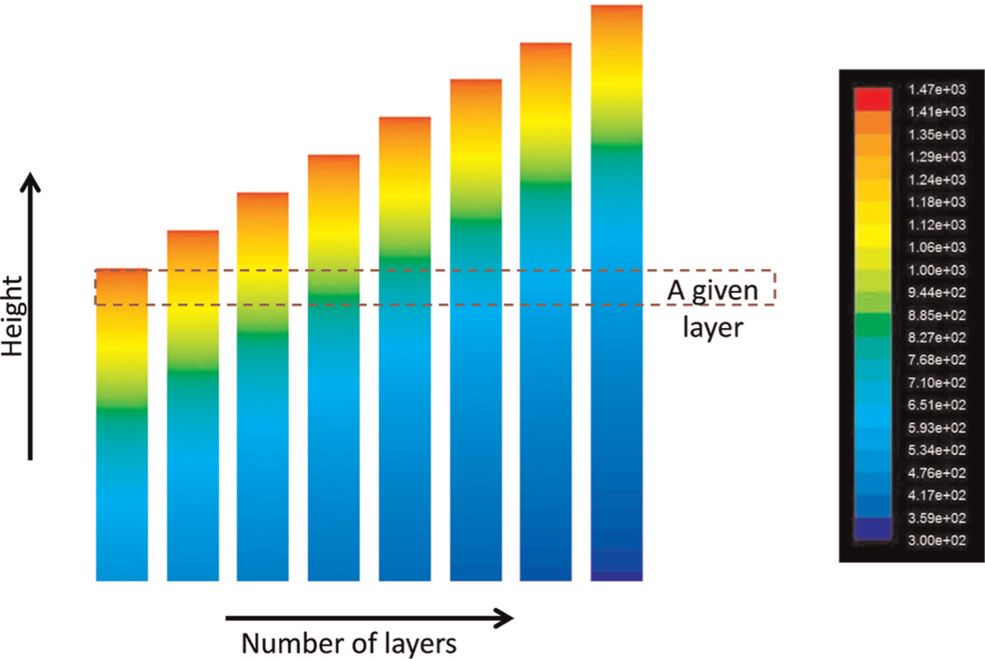
A given layer being subject to varying number of heat cycles with different thermal gradients as the deposition progresses.
Tensile strength
Tensile testing is crucial in evaluating the behavior of engineering materials as well as in assessing the amount of materials for use in design. Most objects made using RM techniques tend to show anisotropic properties due to the layer-by-layer manufacturing process. Thus, a deeper study of tensile behavior of HLM matrix along various directions was felt necessary.
Methodology
The tensile strength of the HLM matrix was analyzed using ASTM A370 standard. This standard is exclusively meant for fully welded objects and hence is applicable to HLM. The geometry of the tensile specimen specified in this standard is shown in Figure 7. The process parameters used in preparation of the specimen, as listed in Table 2, are same as those used for hardness evaluation. These specimens were prepared in all the three directions, namely, torch direction (X), stepover direction (Y), and build direction (Z). Four blocks of 140 mm × 120 mm × 10 mm, as shown in Figure 8(a), were prepared. Four specimens, two each for X and Y directions, were cut out of each block. Similarly, the Z specimens were cut from another block of 20 mm × 15 mm × 120 mm (Figure 8(a)). These blocks built are given in Figure 8(b). The tensile specimens were manufactured from these blocks using a wire-cut electrical discharge machining (EDM) machine. These specimens were tested in EZ50 universal testing machine manufactured by Lloyd Instruments. Using standard deviation, the error in each of these directions for the total of eight samples per direction was calculated. These results were compared with the properties of a MS Billet of similar composition (420MC steel confirming to DIN EN 10149-2).
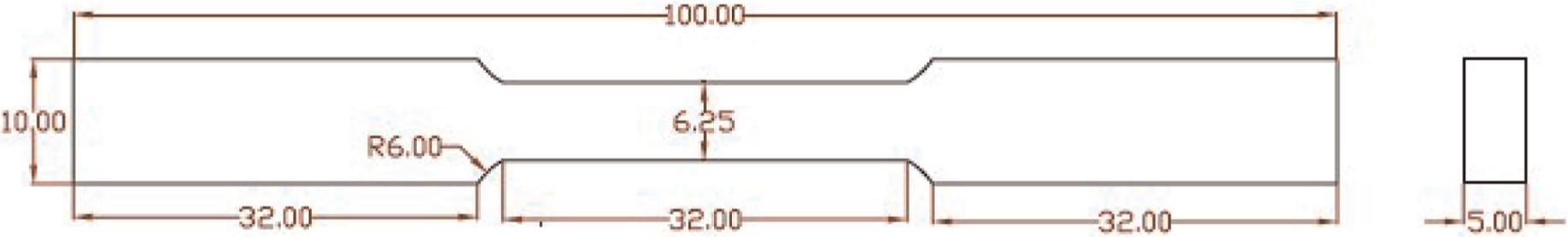
Dimensions of ASTM A370 test specimen.
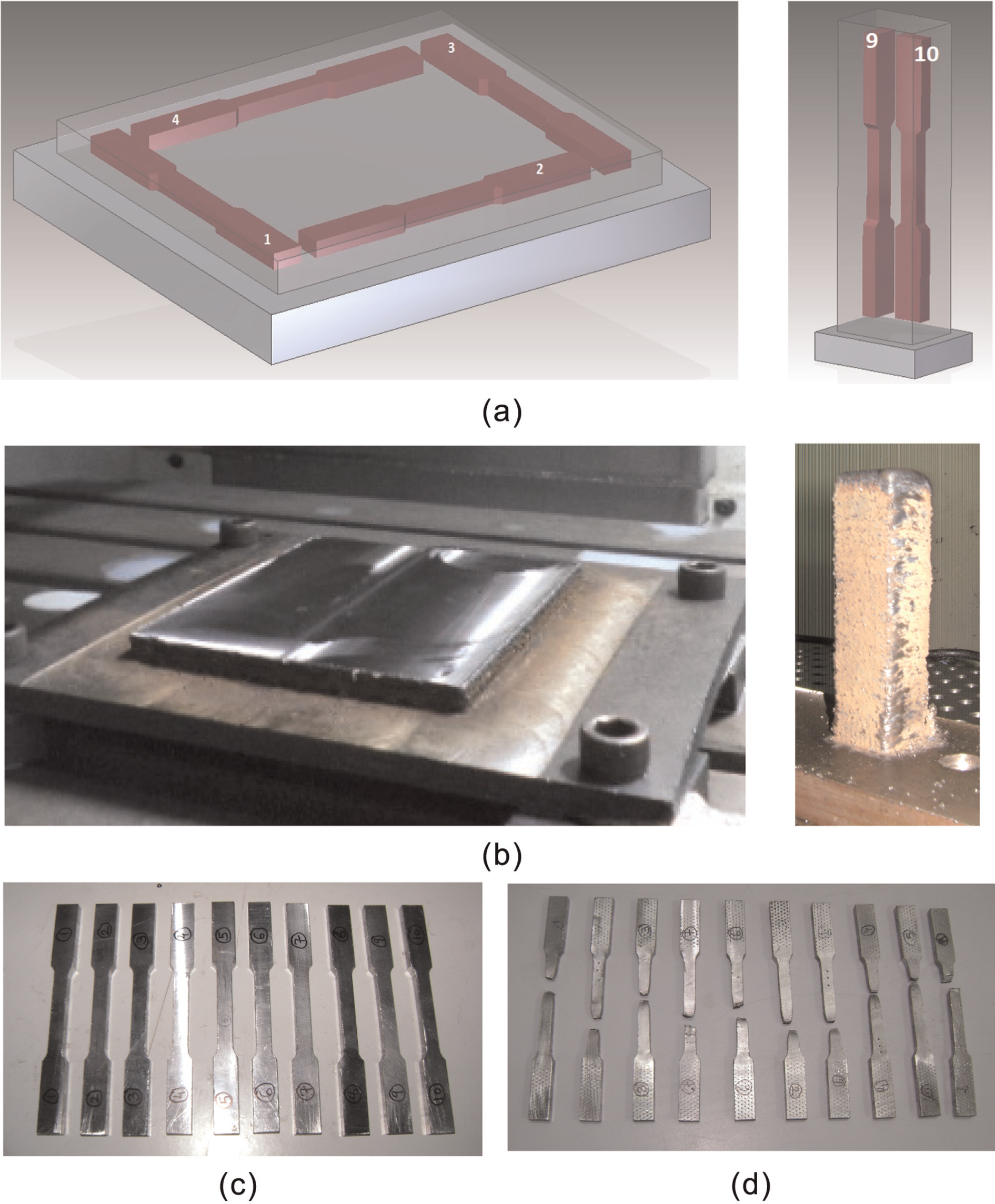
Specimen for tensile testing: (a) plan of specimens for X–Y and Z directions, (b) deposited blocks, (c) specimen before testing, and (d) specimen after testing.
Experimental results
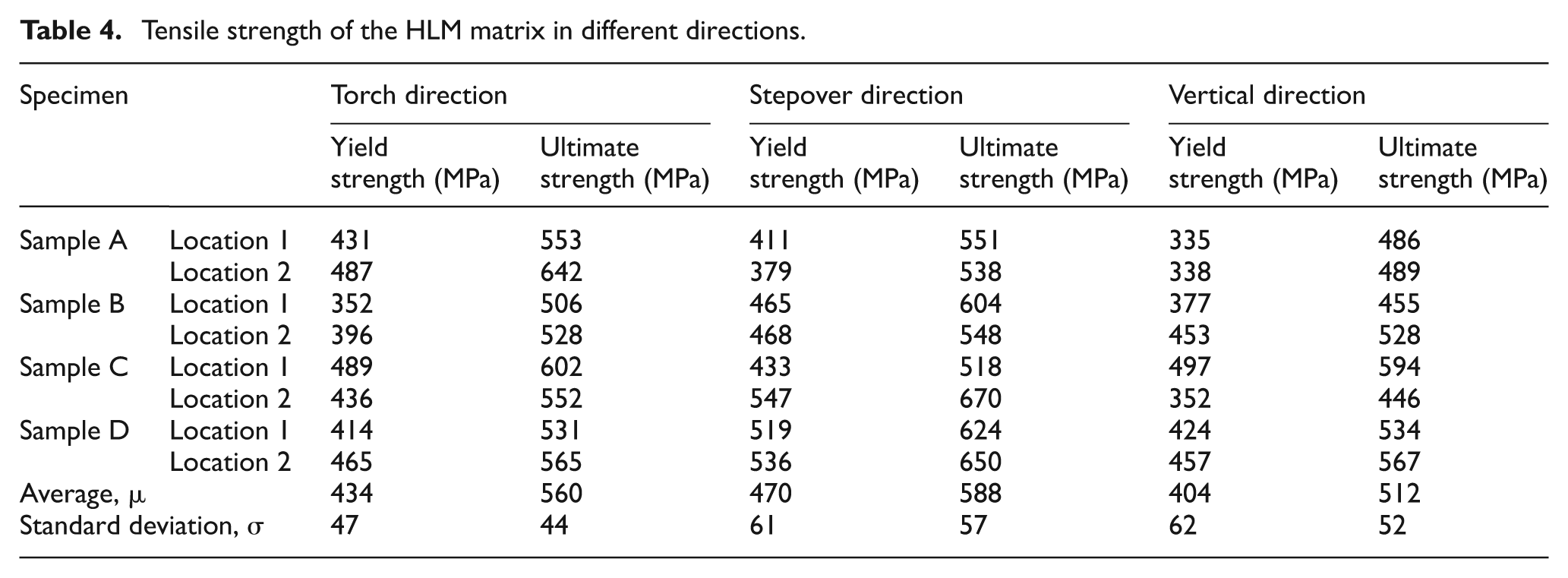
Figure 8(c) and (d) shows some of the specimens before and after testing, respectively. The yield and ultimate strengths are the two important mechanical properties to be inferred from these tensile tests. These values for all the specimens, along with the error analysis, are summarized in Table 4. Furthermore, the variation of the ultimate strength along the three different directions is depicted in Figure 9.
Tensile strength of the HLM matrix in different directions.
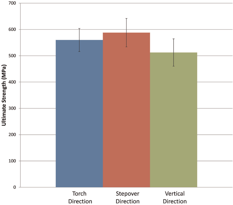
Ultimate strength in the three different directions.
Discussions
Table 5 gives the comparison of the tensile strengths of the HLM matrix with that of the billet. It may be noted that the properties of HLM matrix are within the ±σ range; in other words, the deviation of the properties of HLM matrix with respect to billet is within the error margin. It was found that the average yield and ultimate strength varied only by 7.6% and 4.8%, respectively, between the torch and stepover directions, implying negligible variation of strength in XY plane. However, the same for vertical direction varied by 10.6% and 10.8%. Further experiments were conducted to study the influence of current on the tensile properties along vertical direction for different values of current. Figure 10 plots the ultimate strength of the specimen for different values of current. From Figure 10, it is clear that the tensile strength of the HLM matrix can be further improved by increasing the current. This is due to improved penetration with increase in current, resulting in higher weld strength and tensile properties. 22 Therefore, it is possible to achieve same tensile properties in all the three directions while suitably increasing the current.
Comparison of tensile strengths along various directions with respect to a billet.
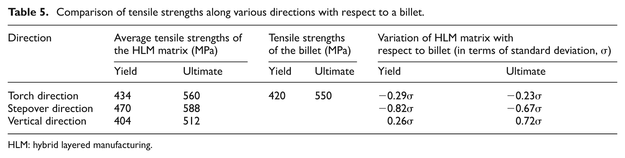
HLM: hybrid layered manufacturing.
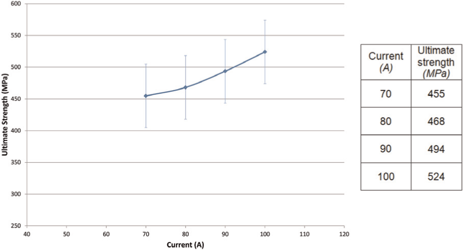
Ultimate strength in the vertical direction for different values of current.
Composite matrix
Gradient objects have controlled variation of the material composition throughout the matrix so as to obtain the desired distribution of the properties such as color, density, porosity, hardness, and toughness. No natural object is uniform; they are all gradients throughout. Examples are bamboo, bone, stone, and so on. However, most man-made objects are uniform both due to the inability to design them and subsequently manufacture them. The bottleneck today for the use of gradient objects is the design tools. The CAD models define only the boundary, and the interior is assumed to be filled with uniform matrix.
The objects built through layered manufacturing are inhomogeneous or nonuniform, that is, they are inherently anisotropic. When this inherent nature is carefully exploited, the anisotropy transforms into the desired distribution of the properties. ZCorp’s 3D printing is able to produce color prototypes out of starch in this manner. Similarly, Therics has adopted 3D printing to produce time-delivery drugs commonly used by the neurotic patients. LENS is another popular process for making metallic gradient objects through layered deposition. 23 Selective laser sintering (SLM)/selective laser melting (SLM), LENS, laminated object manufacturing (LOM), stereolithography (SL), fused deposition modeling (FDM), three-dimensional printing (3DP), and ultrasonic consolidation (UC) are some rapid prototyping (RP) processes, which have been employed for fabricating composites. 24 These cases demonstrate the emergence of the manufacturing technologies for making gradient objects. The gradient matrix can be realized in mainly two approaches:
Controlled varying the properties of a single material matrix,
Multiple materials.
As discussed in the earlier section, by varying the value of the current in the desired fashion, it is possible to manufacture objects exhibiting gradient properties in a single material matrix. The capability of the HLM for creating gradient matrix with multiple materials is discussed in the following subsections.
Methodology
To realize multiple material deposition, HLM is integrated with two weld-deposition units, as shown in Figure 11, each loaded with different materials. An experiment was done to assess the bonding tendency of the matrix made through this setup. A hard filler wire (P20 tool steel) and a softer one (mild steel) were loaded onto the two weld-deposition units.
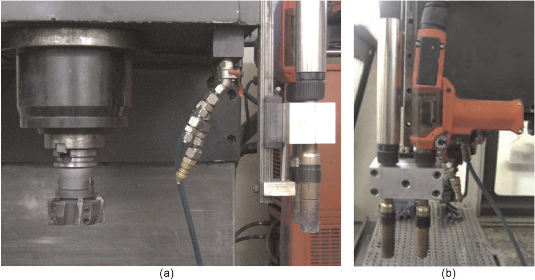
Weld-deposition torches with different materials fixed to the CNC: (a) front view and (b) side view.
Experimental results
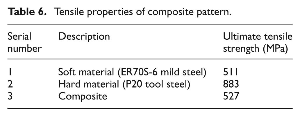
The two patterns shown in Figure 12 were deposited, one using each material. From this deposited matrix, three tensile specimens, shown in dotted lines, were prepared. The results of the tensile testing are given in Table 6.
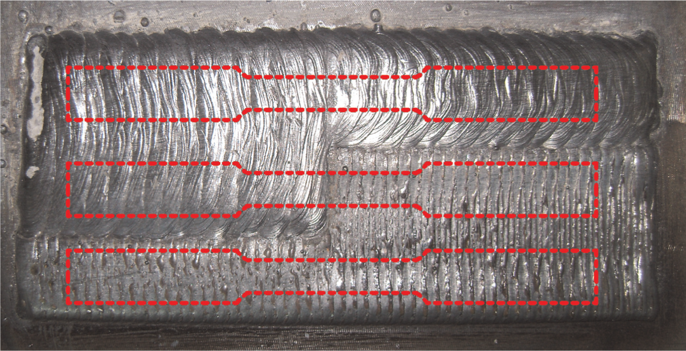
Pattern for testing the tensile properties of composite deposition.
Tensile properties of composite pattern.
Discussion
The strength of the joint varied by only 3% to that of the weaker material. This indicates good bonding of the two materials.
Conclusion
The mechanical properties, including analysis of their tensile properties and hardness variation, built through weld-deposition have been presented. It was found that hardness variation exists only in the final layers. From the maximum point in the final layers, it falls rapidly within a thickness of few layers, about five layers, before stabilizing. In other words, the interior matrix has negligible hardness variation. Tensile strength experiments revealed that the average yield and ultimate strength varied only by 7.6% and 4.8%, respectively, between the torch and stepover direction, implying negligible variation of strength in XY plane. However, the same for vertical direction varied by 10.6% and 10.8%. Subsequent experiments showed that it is possible to achieve similar tensile properties in all the three directions while suitably increasing the current. Hence, it can be suggested that the properties of HLM are comparable to those of objects made using conventional means like CNC machining. They can be further improved through an appropriate thermal and/or mechanical treatment such as hot isostatic pressing (HIP) or simply a heat treatment.
The ability of HLM to make composite objects was also studied. It was also found that the tensile strength of the bond is stronger than the tensile strength of the weaker material. This denotes good bonding of the two materials.
Footnotes
Conflict of interest
The authors declare that there is no conflict of interest.
Funding
This study was supported by the Ministry of Information Technology, Government of India.