
Abstract
This article presents a novel linearity amending system for the precise film potentiometer. The proposed mathematical model for this film resistor can accurately describe the electrical characteristics of the potentiometer and estimate the thickness of carbon film, which is the source of linearity error. The voltage–position curve is measured first to model each unique potentiometer. Due to the noise and interference, the detected data have some outliers in the measurement. Next, a new algorithm to process the outliers of the data is proposed, which can identify and eliminate the noise interference. Finally, a cut profile is given to modify the linearity of potentiometer based on the model. The laser fixing robot was developed to check and improve the linearity of potentiometer, with the laser processing technology, to remove the redundant parts. Experiments illustrate the proposed method.
Introduction
Precise film potentiometer (PFP) is widely used in the military, industry, aeronautical and astronautical industries, auto industry, sophisticated manufacturing and so on. PFP enhances performance in several aspects, such as thermostability and insulation. Additionally, it mitigates dynamic noise and erosion.1,2 In an electrohydraulic servo system, it acts as an essential position feedback sensor. PFP is made of a liquid resistor coating on a nonconducting substrate. The liquid resistor consists of graphite, carbon black, resin and other materials (Figure 1). It is difficult keeping the thickness of the resistor invariant in the coating procedure, which results in a linear error of the potentiometer. With the development of electronics, the improved performance requirements of PFPs are increasing. Linearity can be improved manually to achieve a better performance, but this is an inefficient process, and the minimal effect gained does not merit the energy expenditure. Therefore, designing an autonomous amending system is a necessity.
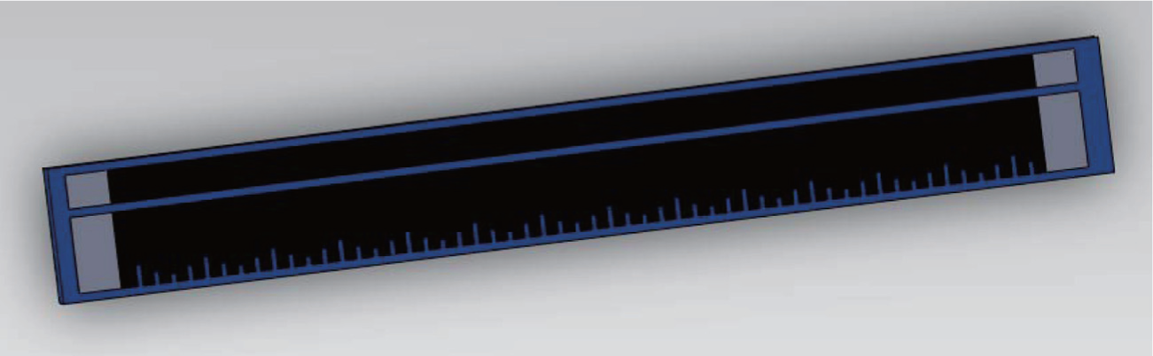
The sample of a precise film potentiometer.
Currently, there are three dominant methods available. They are the abrasive wheel polishing method, the milling cutter method and the laser cutting method. Operators implement the abrasive wheel polishing method,3–5 and it is inefficient and imprecise. The milling cutter method uses a special carved header to cut the film resistor. The cutting in this method is not continuous and the precision cannot be guaranteed. Hence, these problems require a new solution.
The laser cutting method is a recently developed technology.6–9 The advantages of laser cutting include a high degree of accuracy, continuous cutting, free of noise, higher productivity and decreased maintenance costs. This technology requires an accurate mathematical model to describe the potentiometer. Furthermore, the data processing technique, as well as the laser fixing robot (LFR) and control strategy, needs additional research for use in the amending system. As a result, there are not many products currently available to satisfy the requirements of using this technology. The open architecture for computer numerical control (CNC) systems, based on PC-control technology, has been extensively used in previous decades.10,11
This article reports on the construction of the mathematical model for the film resistor. Additionally, a new algorithm to process the data is proposed to calculate the cutting line based on measurement results. Finally, the LFR is introduced. The experimental results show that the system can meet the requirements to achieve the desired result.
This article is organized as follows: section “Problem statement” describes the mathematical model of the film potentiometer. Section “Data processing” introduces a new method to identify and eliminate outliers. In section “System implementation,” a robot is designed to modify the potentiometer. Experimental results are provided in section “Experiment,” with section “Conclusion” concluding the article.
Problem statement
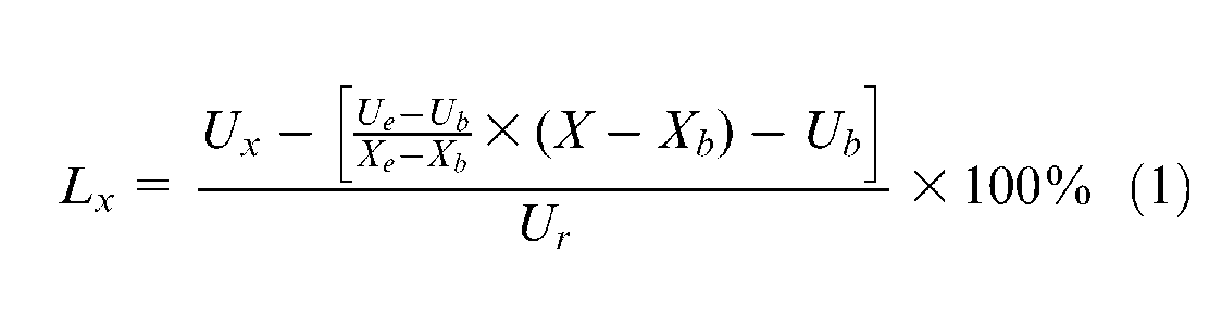
In order to estimate the quality of an PFP, a definition of linear error is produced. Considering a rectangular potentiometer, define Lx as the linear error at the position x in equation (1) and L as the mean linear error of the potentiometer in equation (2). How L varies with x and Ux is shown in Figure 2. Generally, the L of a rough potentiometer is about 3%. The required linear error of qualified products should be within 1‰
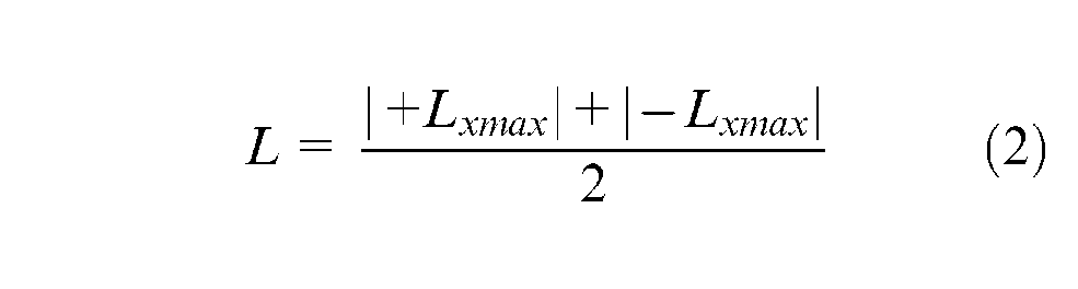
The demonstration of linear error.
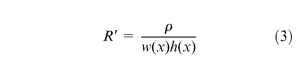
In this article, the film resistor is considered as a general resistor model. The resistance value R is given by R = ρ×l/S, where l is the length of the resistor and S represents the cross-section area of the film resistor. As S is not uniform everywhere, the R value is not linearly dependent on l. In order to identify how S is related to l, the concept of resistance density R′ is introduced in equation (3), where x is equal to the displacement of brush, w(x) is the width of S and h(x) is the thickness of the film. A sketch of the film resistor is shown in Figure 3
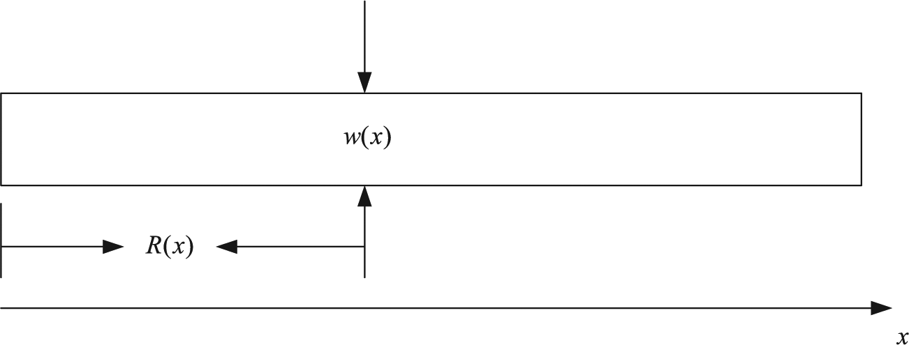
A schematic diagram of the film resistor.
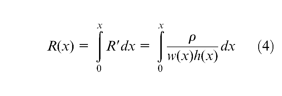
Then, the resistor of the potentiometer R(x) is given by
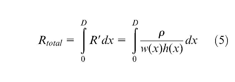
Denoting D as the length of the film resistor, the total resistance of the film is
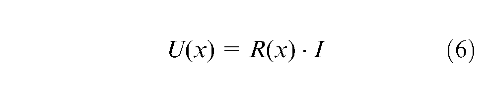
When constant currents flow through the resistor, the voltage U(x) can be detected, where
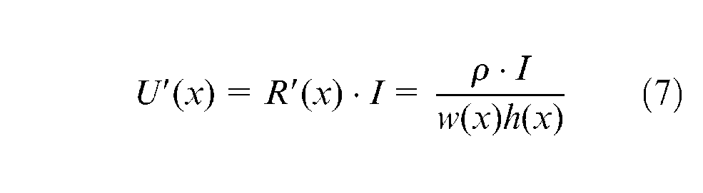
The derivative of U(x) is
Then S(x) can be calculated by
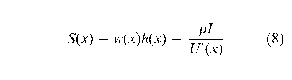
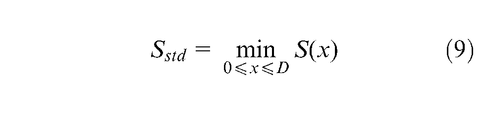
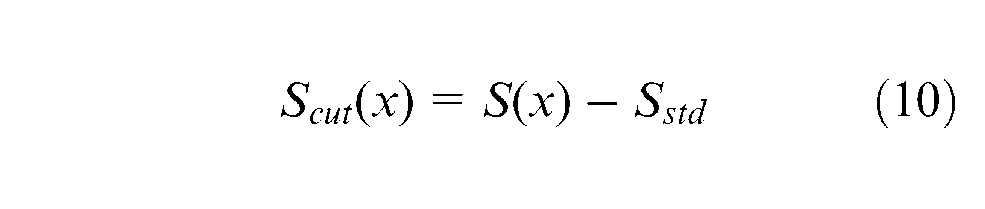
The measuring system can get U(x) from the high-precision voltmeter as the brush moves along x, and S(x) is then obtained from equation (8). The cross-section area S(x) varies with x, which leads to Lx. The proposed method modifies S(x) to meet the linearity requirement. Laser cutting technology is used to cut the film and to ensure S(x) in a small fluctuation range. In order to make the cut film as small as possible, the smallest S(x) is chosen as the standard area Sstd
Then the theoretical area to be cut is
Practically, the unstable thickness is the main cause of the difference of S(x). According to the film resistor manufacturing technique, the crosswise thickness is well proportioned; however, the lengthways thickness, in general, fluctuates. The solution is to modify the width to reduce the waviness of S(x). Consequently, the width to be cut, wcut, is (Figure 4)
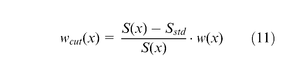
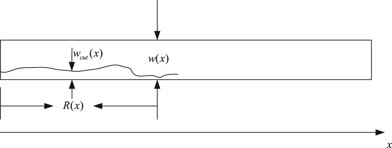
The theoretical cut profile to improve linearity.
The small change on w(x) can be ignored, thus w(x) = 10 mm. Then
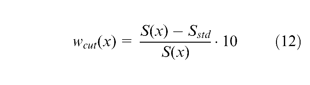
Now the cutoff width can be calculated. The following sections focus on eliminating the measurement error and implementing the amending robot.
Data processing
The first step of the amending process is measuring data. When constant current flows through the resistor, the voltage could be detected as the brush is driven along the resistor. The voltmeter needs a settling time when measuring data. The contact area between the resistor and brush changes with high frequency when the brush is moving. In addition, the process has some other noise that would result in an unstable voltage. Therefore, the voltage data are not accurate. The noise in the measured voltage data makes wcut(x) vary frequently. U(x) is singular, particularly at the head and end part of the resistor. The measuring process contains outliers, which need to be identified and eliminated before calculating the cutting line.12,13 An algorithm is proposed to process the outliers. In order to explain the progress of the algorithm, a group of data was sampled from a potentiometer whose length is 50 mm. The detected and theoretical voltage–position curve is shown in Figure 5. It is obvious that the curve is not strictly linear.
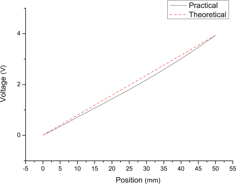
The voltage–position curve of a 50-mm-length potentiometer.
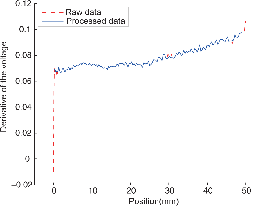
Following the method in section “Problem statement,” the derivative of the voltage is U(x). The derivative–position curve of the resistor is shown in Figure 6. This indicates that at the beginning of the data, U′(x) brought by the outlier is much worse than the other parts and even be negative, which must be a positive number. The carving line calculated from the raw data is shown in Figure 7. With the restricted width of the brush, the cutting size is limited to 3 mm. Figure 7 shows that the cutting volume outdistances the limitation. In order to satisfy the restriction, the singular value must be identified and removed.
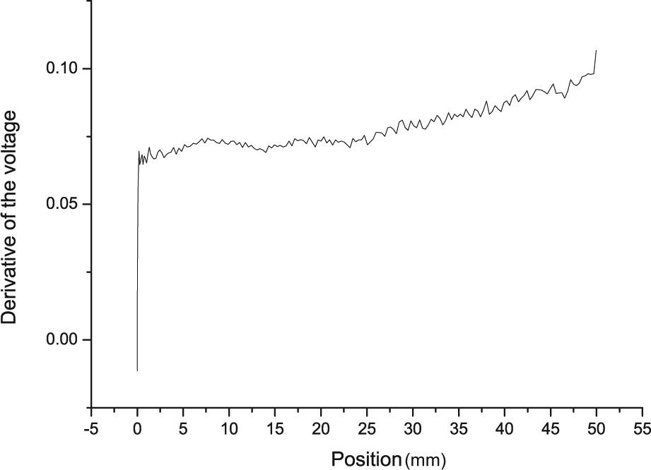
The derivative–position curve of resistor.
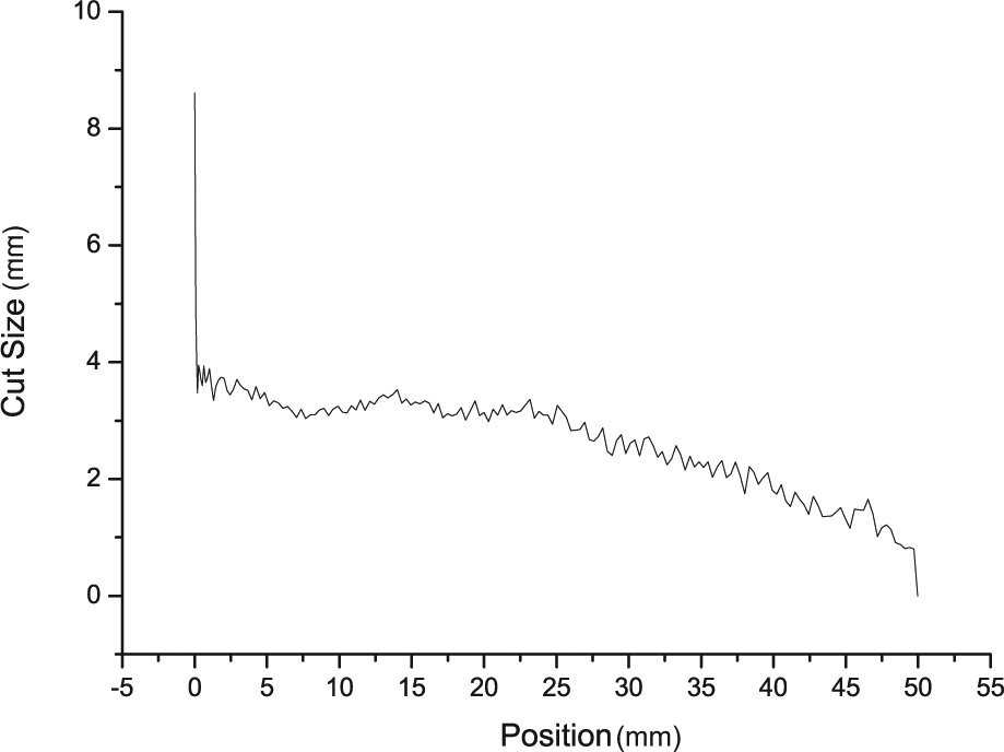
The raw carving line to modify the potentiometer.
There are four leading methods to distinguish and eliminate the outliers, Peirce’s criterion, Chauvenet’s criterion, Grubbs’ test and Dixon’s Q test.14–16 They are based on statistics principles and are appropriate for repeating data and linear data. According to this problem, these methods are inapplicable; hence, a new way to distinguish the outliers needs to be developed.
Since the thickness of the film resistor is diverse, U′(x) is variable. Suppose that the thickness of the film along the length changes slowly, then each small segment of the data has the same value of U′(x) and each point belongs to one of the local segments. Based on the proposed method, every segment of data follows a straight line. The distance between the point and the straight line can be used to judge the quality of a point regressing to the segment. For each segment of data, the regression model is Y = a+bX+ε, where a is the intercept, b is the slope of the regression line and ε is a random variable following a normal distribution ε∼N(0, σ2).
First, the best length of local segment data needs to be determined. Next, the traversal method, from
Searching the suitable length of local data segment
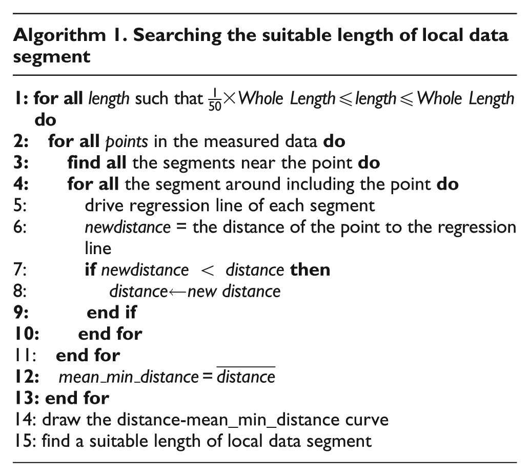
Figure 8 shows the relationship between length of resistor and the mean distance σ2. When n is close to 50, the variance σ2 is too large, and the result is rough. However, when n is a small value, for example, approaching 1, the randomness of the regression line is too large. The proper n corresponds to the smallest acceleration of σ2. According to Figure 8, when n is between 13 and 20, the increment speed of mean distance is gradual. However, from a local viewpoint of the data in the head or end part, the density of outliers is much higher than the average level. Therefore, in the local area of the head or end part, n needs to be reduced to fit the situation. According to the numerical result, the algorithm is effective in distinguishing the outliers with n = 10, where
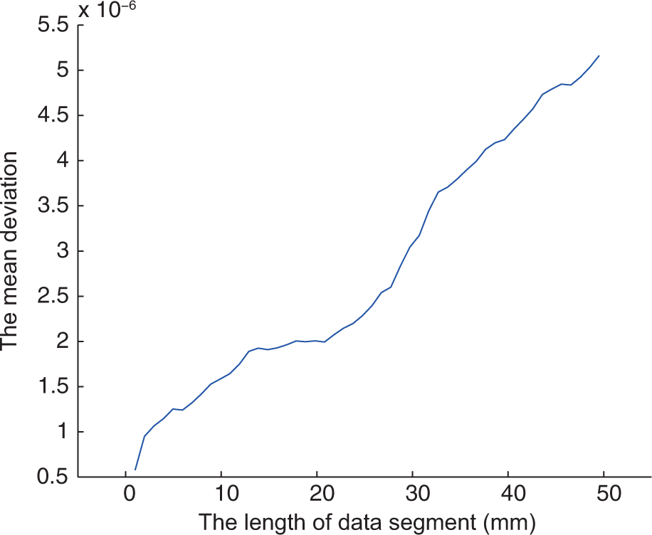
The curve of relationship between regression length and mean variance.
As the local data fit to model
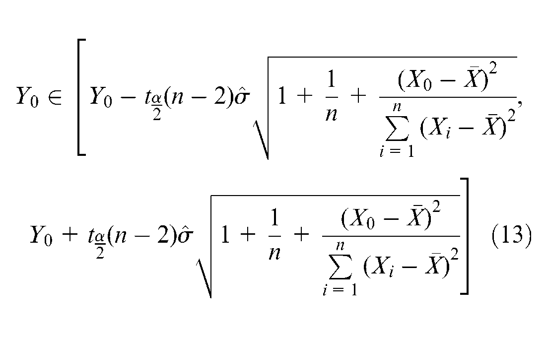
where Y0 = a+bX0 and
A suitable confidence level 1 −α is required to detect the outliers, thus α = 0.2 and
The derivative of voltage before and after eliminating the outliers.
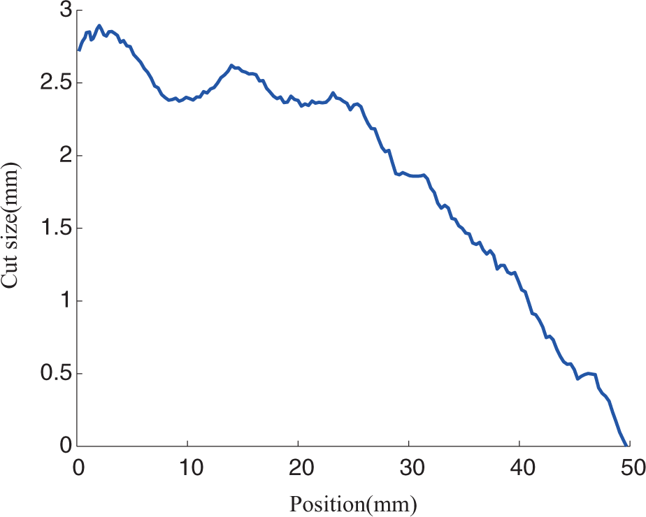
The carving line from equation (12) is shown in Figure 10. It is obvious that the curve is rough. It is hard for the motor to follow the path accurately, and it is harmful for the long-term usage of the motor. A low-pass filter to smooth the curve line is studied here. Using the high-order multi-parameters polynomial fit method does not produce good performance. Here, the filter chooses y(k) = γ×y(k− 1) + (1 −γ) ×w(k) to improve it. The curve line after a low-pass filter is shown in Figure 11.
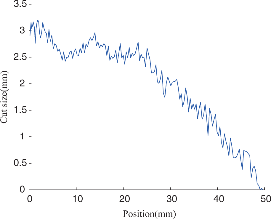
The cut profile after data processing.
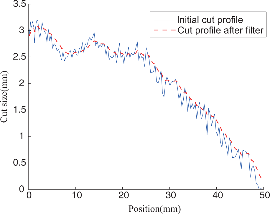
The curve line after low-pass filtering.
The cut volume is too minimized in the process. A curve adjustment is required to make the minimum cutting volume zero. By shifting the curve, Figure 12 shows the ultimate carving line for the laser to follow. In some cases, the maximum cutting volume of the ultimate carving line is larger than 3 mm. In order to satisfy the maximum constraint, the method is to select the part of the curve where the height is 3 mm, which makes the unselected area minimal. As shown in Figure 13, the striped area represents the unselected area. Then we shift the curve to zero, which is a minimal cut volume. In this way, L can be kept at the smallest value and simultaneously meet the cut volume limit.
The final profile to cut by laser.
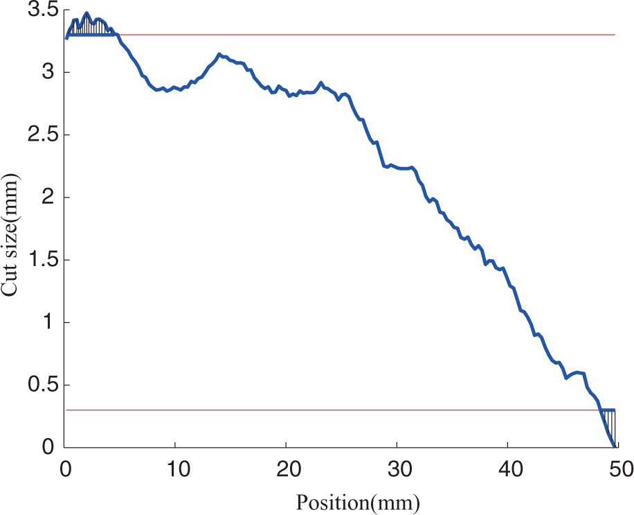
The method to shift curve line.
The beam diameter is less than 0.4 mm, and there is a margin about 2 mm between the edge of carbon film and the edge of the plastic substrate. When the amending work starts, the cutting point of the laser beam will be adjusted to the datum point, which ensures the cutting volume is zero, so the width of the laser beam will cause fewer errors. Assume that the laser beam increases cutting volume Δw. Since the whole profile has a small shift, where the change volume is the same everywhere and the resistor density is well proportioned, there is little influence on the linearity.
System implementation
LFR has been built for cutting redundant film resistors following a calculated profile. The functions of LFR include measurement and automated carving of carbon film resistors. The main parts of the machine are the 1R1P manipulator with the laser cutting head and the high-precision measuring system. The 1R1P manipulator has two joints. The prismatic joint drives the brush as the laser gun moves along the resistor. The rotary joint controls the cutting volume of the laser. It consists of three sections. First, constant current flows through the resistor, then the brush is driven by the motor from one end of the resistor to the other. After a simple transformation, the linearity data can be measured. Based on the steps in sections “Problem statement” and “Data processing,” the carving line can be calculated. Next, the system drives a laser, following the curve, and a split line burned by the laser light can separate redundant resistors out of the potentiometer. Finally, the operator needs to clear the ash and cut off the border manually and measure the linearity again. At that stage, the amending work is finished. The linearity error can be reduced to a minimum. The frame of the system is shown in Figure 14.
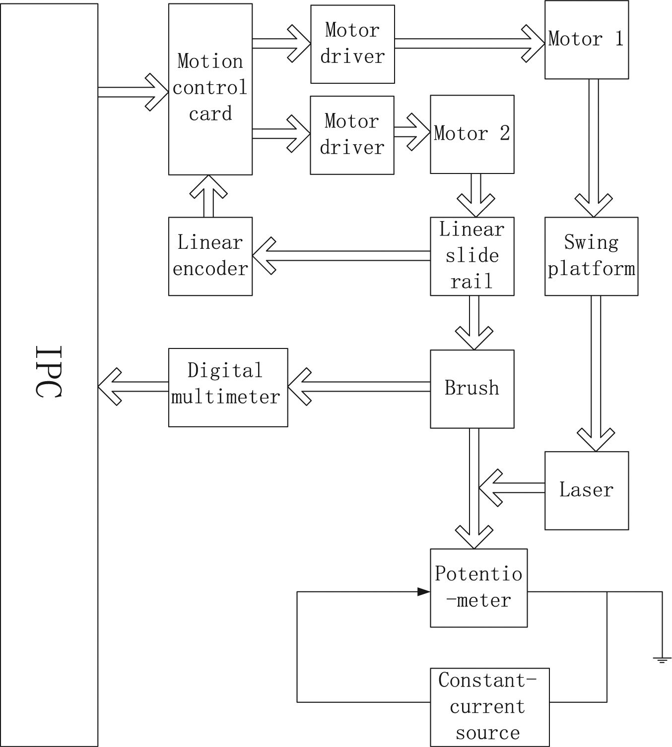
The diagram of system hardware. IPC: Industrial Personal Computer
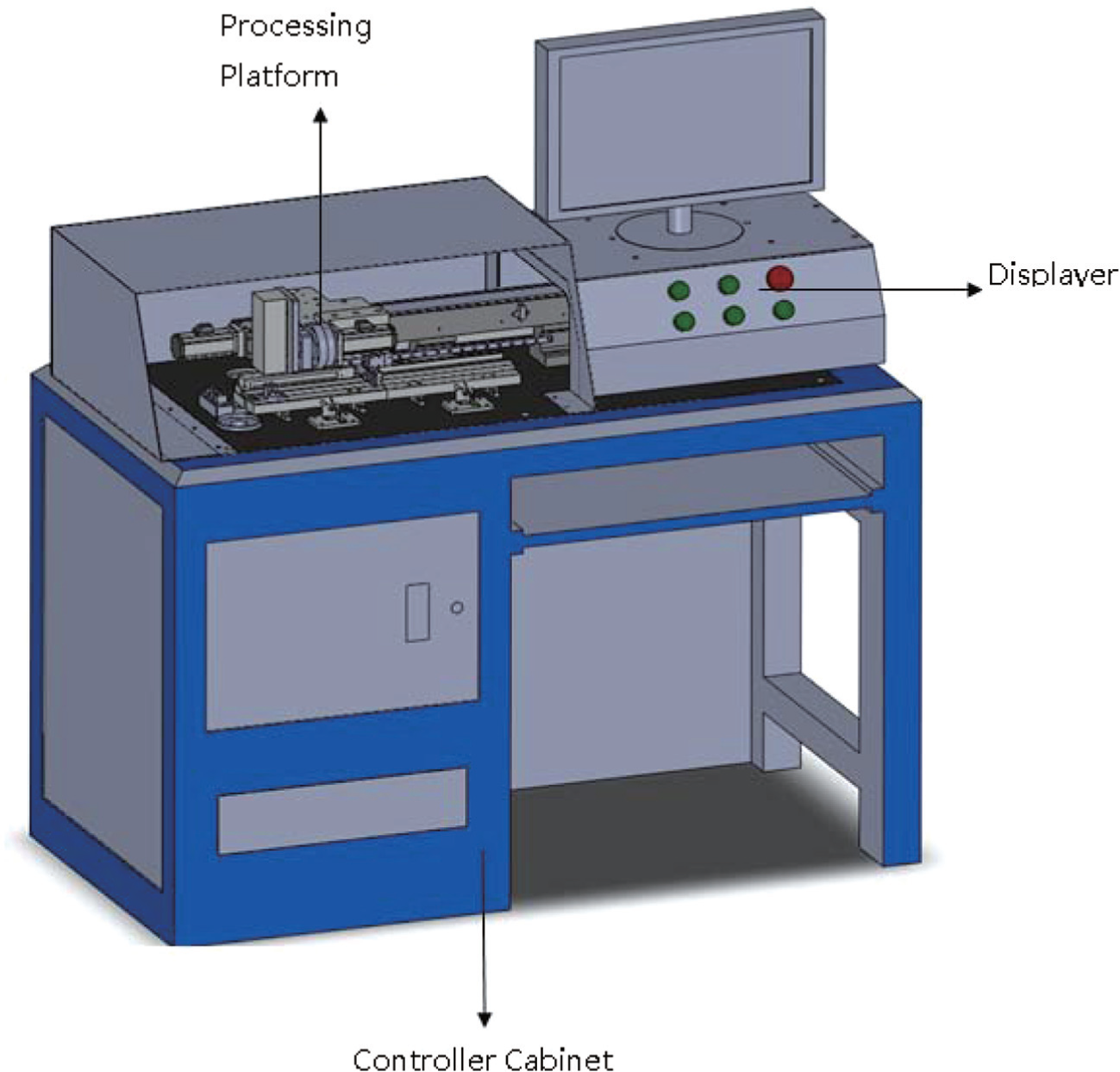
The mechanical system consists of a controller cabinet, a displayer and a processing platform. The processing platform is the core part, where a two-axis positioning robot drives a brush and a laser to finish the measuring and modifying procedure (Figure 15). One axis is driven by an alternating current (AC) servo motor (MINAS A5 series of Panasonic) transmitted by a lead screw. There are two closed loops on it. One is the rotary encoder on the motor to get a closed speed loop and the other is a grating (Product ID:LE-500 of IMCOR) for an open position loop. The two loops ensure the precision of the displacement along the length. The other axis controls the laser’s cutting volume. It swings the laser device to adjust the angular dimension. The harmonic gear reducer on this axis has a transmission ratio 1:100, which ensures the rotating torque and precision, satisfying requirements. The rotary encoder on the axis provides the closed loop of speed and position. The laser has a beam diameter of about 0.4 mm, and the operation efficiency is about 30 s/cm. The controller cabinet consists of a constant-current source, a digital multimeter, an IPC and a robot controller. The constant-current source changes the current to make the total voltage a definite value. A sketch of the mechanical system is shown in Figure 16.
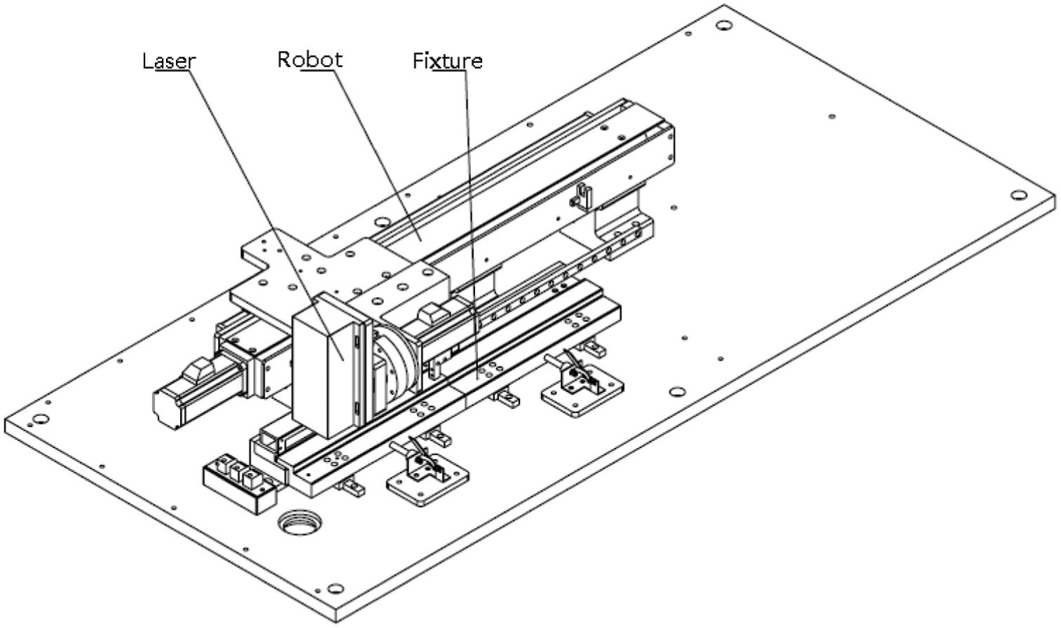
Processing platform structure.
The system mechanical sketch.
The LFR comprises a CNC controller and a graphical user interface (GUI) implemented on a PC-based system. The control system performs various tasks for LFR: time-critical servo control of position loops, acceleration, deceleration, numerical control path generation, program loading and interpreting, GUI, file management and data processing. The control interface, which utilizes the high-performance multifunction input/output (I/O) board for PC motion-control applications, connects the constant flow source, the digital voltmeter and several limit sensors. The GUI connects user I/O devices, which brings all the displays and functions together for machine management. This was developed to provide a user-friendly machine operation control that allows for easy diagnostics and maintenance.
The working sequences of the system are described as follows. First, the potentiometer is clamped in the working position and connected to the constant-current source by the conductors. Next, a fully automated computer-controlled measurement is achieved and the linear error is calculated. The proposed curve is based on the above algorithm. The laser light burns through the film resistor and carves a line to modify the potentiometer. After that, the system measures the linearity again to check whether the result meets the requirement.
Experiment
For the sake of the system’s reliability, it is important to confirm performance through an experiment. In this section, three groups of potentiometers with lengths of 50, 100 and 150 mm are modified. Each group of potentiometers is selected randomly with a different linearity error. Five raw potentiometers for each length are selected, and the linearity error is measured before amending the potentiometers. The robot modifies the potentiometers according to the steps described above, and the linearity error is measured again. The experiment data is given in Table 1.
Experiment results.
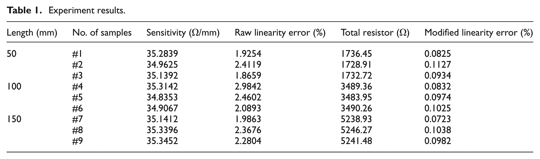
It can be seen that the amending system has a good performance, where the required linearity error of the qualified products is less than 0.1%. However, reaching the required standard is difficult since the raw potentiometer is tuned manually. Actually, if the linearity error of a modified potentiometer is lower than 0.2%, the product is accepted. The failure rate is close to 10%. This is not only wasteful but also leads to higher costs. The amending process not only improves the linearity precision but also reduces the rate of product disqualification. Figure 17 shows a sample of the film potentiometer modified by this system.
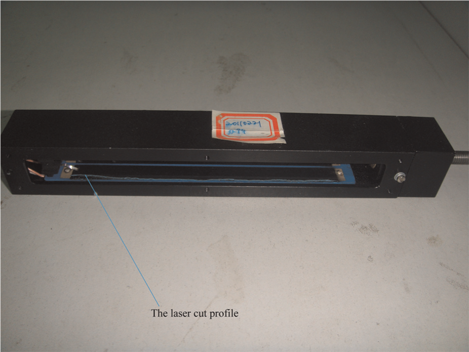
A sample of the modified film potentiometer.
Conclusion
Based on the mathematical model of the rectangular resistor, we can find the variation in thickness along the length. The linearity can be modified by adjusting the width of the film resistor. The proposed algorithm, which can detect and eliminate the outliers, improves the precision of the carving line.
The potentiometers can be measured by the mechanical system automatically, and then the carving line can be obtained. The amending system drives the laser to carve a preset line. Then the modified potentiometer is measured again to verify the carving result. The performance of the system is satisfactory. Future studies will focus on the burn effect between the laser and the film resistor, which might also influence the linearity.
Footnotes
Appendix 1
Funding
This work was partially supported by the Research Fund of State Key Laboratory of Mechanical Systems and Vibration (MSV), China (grant no. MSV-MS-2010-03), the State Key Laboratory of Robotics and System (HIT) (grant no. SKLRS-2010-ZD-06) and the National Natural Science Foundation of China under grant nos 61105101 and 61075086.
Declaration of conflicting interests
The authors declare that there is no conflict of interest.