
Abstract
Aluminium metal matrix nanocomposite reinforced with 0.5 wt% B4C nanoparticles was prepared by a novel ultrasonic cavitation method. The metal matrix nanocomposite was studied microscopically to ascertain the uniform distribution and the degree of dispersion of the B4C nanoparticles within the aluminium metal matrix. Electrical discharge machining was employed to machine the metal matrix nanocomposite with copper electrode by adopting response surface methodology using face-centred central composite design technique. This method has been applied to investigate the influence of process parameters and their interactions. Furthermore, a mathematical model has been formulated in order to study the machining characteristics. It has been observed that pulse current was found to be the most important factor that affects the characteristics of all the three output parameters such as material removal rate, electrode wear rate and surface roughness. The pulse current and pulse on time have statistical significance on both electrode wear rate and surface roughness. Higher pulse off time lowers the electrode wear rate value, whereas both pulse current and pulse on time increase the electrode wear rate. Similarly, surface roughness also increases with increase in pulse current and pulse on time. From the analyses, the optimum combination of the parameters has been identified for the metal matrix nanocomposite. The results obtained from the confirmation experiments were compared with the experimental results and found that errors are in the acceptable range.
Keywords
Introduction
Aluminium metal matrix nanocomposites (MMNCs) are a new class of nanostructured materials consisting of nanoscale particles used as reinforcements. Generally, micron-sized ceramic particles are added so as to improve the mechanical properties of the materials. However, the ductility of the metal matrix composites (MMCs) deteriorates with increase in ceramic particle concentration.1–3 Therefore, researchers focus their attention on the nanosized ceramic particles with an objective to strengthen the metal matrix, along with good ductility. It is expected that MMCs reinforced with ceramic nanoparticles (less than 100 nm), termed as MMNCs, can overcome those disadvantages associated with the conventional MMCs. When compared with the corresponding MMCs, the properties of MMNCs would be enhanced considerably even with lower volume fraction of nanoparticles. It has already been reported that MMNCs could especially provide a significantly improved performance at elevated temperatures. 4
Even though several fabrication methods of MMNCs exist, namely, mechanical alloying with high-energy ball milling, ball milling, nanosintering, vortex method, spray deposition, rapid solidification, electroplating, sputtering, laser deposition and sol–gel synthesis, they cannot be used for mass production and net shape fabrication of complex structural components. 5 Solidification processing such as stir casting utilizes mechanical stirring to produce aluminium MMCs, which are reinforced by micro-ceramic particles. Nevertheless, a combination of good distribution and dispersion of micro-particles can be achieved by mechanical stirring. 6 If this technique is extended to fabricate MMNCs, it posses lot of challenges to distribute and disperse nanoparticles uniformly in melts because of their higher specific surface area. In order to achieve a uniform dispersion and distribution of nanoparticles in aluminium MMCs, Lan et al. 7 developed a new technique that combined solidification processes with ultrasonic cavitation–based dispersion of nanoparticles in metal melts. The full potential of these materials hindered the difficulties experienced in machining of MMCs. Machinability of MMCs has received considerable attention because of their high tool wear, which is caused due to the presence of the hard reinforcement particles.3,8 This hard reinforcement particle causes premature failure of the cutting tool, which leads to higher machining cost. The efficient and economic machining of MMCs is essential so as to obtain the desired dimensions and surface quality. Due to possession of higher hardness and reinforcement strength, composite materials are difficult to be machined by traditional techniques. Hence, electrical discharge machining (EDM) process becomes a viable method for these kinds of composite materials. Since the EDM process does not involve mechanical energy, the material removal rate (MRR) is not influenced by the material properties such as hardness, strength and toughness. 9
It is observed that materials with poor machinability such as cemented tungsten carbide and composites can also be processed without much difficulty by the EDM process. 10 Narendar Sing et al. 11 presented the correlation between the major machining parameters, electrical current and on time, and crater size on machining of Al/SiC. They concluded that the crater size of Al/SiC was larger than steel, and for effective EDM, large electrical current and short on time were recommended. 11 A study on the feasibility of using EDM process for machining cast Al/SiC MMC was carried out and found that the SiC particles shield and protect the aluminium matrix from being vaporized, thus reduced the MRR. The unmelted SiC particles dropout from the MMC together with surrounding molten aluminium droplets, and the power levels such as voltage and current dominate all other factors and greatly affect the MRR and surface finish. 12 Harmesh Kumar and Paulo Davim 13 carried out an experimental study on the machining parameters in powder-mixed EDM of Al/10% SiC MMC. They mixed silicon powder into the dielectric fluid and reported that the addition of silicon powder into the dielectric fluid of EDM increases MRR but decreases surface roughness (SR). 13 EDM characteristics of nanocomposites prepared by sintered magnesium nano-alumina composites were investigated and reported that the pulse on time showed significant effect on the output parameters. 14 Literatures on the machining of MMNCs are scarce in general and investigations on the characteristics of EDM in particular.
This research work is envisaged to investigate the EDM studies by developing mathematical model and further analysing the effects of parameters on the performance characteristics of MMNC using response surface methodology (RSM). Accordingly, the quantitative mathematical models have been carried out to study the influence of pulse current (Ip), voltage (Vg), pulse on time (Ton) and pulse off time (Toff) on the MRR, electrode wear rate (EWR) and SR by using RSM. 15
Experimental details
Materials used
In this work, aluminium (Al 7075) is used as the base matrix alloy. Its chemical composition (%) is Si = 0.2, Fe = 0.22, Cu = 2.0 max, Mn = 0.1, Mg = 2.1–2.9, Zn = 5.1–6.1, Ti = 0.1 max, Cr = 0.2 and Al comprises the remaining. The aluminium matrix was reinforced with 0.5 wt% of B4C nanoparticles with an average particle size of 50 nm. Boron carbide (B4C) is a high-performance monolithic ceramic of low density (2.52 g/cm3) combined with high strength and an extremely high hardness. Common applications of B4C are armour and wear protection, neutron absorbers in the nuclear industry, bearings, nozzles and turbines. B4C offers higher life for components when compared with SiC and Al2O3 ceramic particles.
Fabrication of MMNCs
Aluminium alloy was reinforced with nano-B4C particles fabricated by ultrasonic cavitation–based solidification processing as shown in Figure 1. It mainly consists of a resistance heating furnace for melting aluminium, protection gas system and ultrasonic processing system. A stainless steel crucible of 110 mm inside diameter and 150 mm height was used for melting and ultrasonic processing. The ultrasonic probe made of niobium alloy was used to generate an 18 kHz and a maximum of 4 kW power output for melt processing. The melt temperature for ultrasonic processing was controlled at about 150 °C above the alloy melting temperature (610 °C). Niobium is a high-temperature element and does not react with aluminium at the melt temperature. Nanosized B4C particles were fed into the aluminium melt through a steel tube.
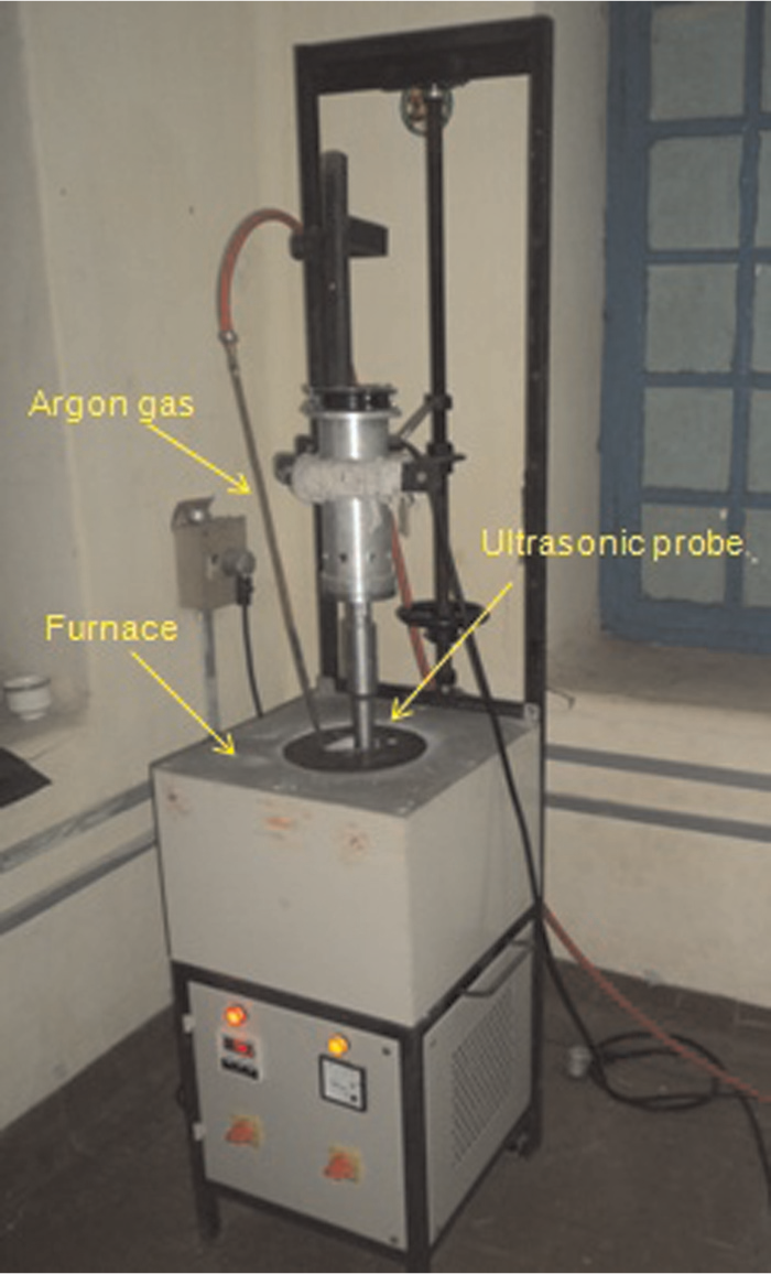
Ultrasonic cavitation setup.
For each casting, about 1 kg of Al 7075 was first melted in the crucible to a temperature of 750 °C. The aluminium alloy melt pool was protected by argon gas. B4C nanoparticles of 0.5 wt% (5 g) were preheated to 800 °C for 1 h in a muffle furnace to improve the wettability. 16 When nanoparticles were added in the Al alloy melts, the viscosity of the Al alloy significantly increased. Thus, after efficient ultrasonic processing, a higher casting temperature of 750 °C was used to ensure the flowability inside the mould. The aluminium melt was cast into a steel permanent mould that was preheated to 500 °C, and Al MMNCs with 0.5 wt% of B4C was fabricated.
Conduct of the experiments
The microstructures and mechanical properties of nanocomposites were studied to understand the effect of nanoparticles in as cast Al 7075 alloys. From the cast MMNCs, the standard tensile specimens were prepared by machining as per dimensions of ASTM E8. For microstructural study, samples of cast Al MMNCs were mounted, mechanically polished down to 0.1 µm by emery paper and etched by Keller’s reagent (2 mL of HF (48%), 3 mL of HCL (concentrated), 5 mL of HNO3 (concentrated) and 190 mL of water). The microstructure of the samples was studied by scanning electron microscopy (SEM) and field emission scanning electron microscopy (FESEM).
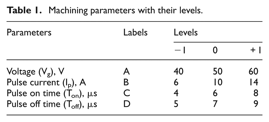
The EDM experiments were designed based on central composite design (CCD) of RSM. The factorial portion of CCD is a full factorial design with all combinations of the factors at two levels (high, +1, and low, −1) and composed of eight star points and six central points (coded level 0), which is the midpoint between the high and low levels, corresponding to an α value of 1. The ‘face-centred CCD’ involves 30 experimental observations at four independent input variables. Table 1 shows both coded and actual values of the four machining parameters and their possible ranges. 17
Machining parameters with their levels.
Results and discussion
Microstructure and mechanical properties of MMNC
The SEM micrograph was taken at high resolution in order to verify the dispersion of nanoparticles, as shown in Figure 2. The nanoparticles are reasonably well distributed within Al matrix barring some micro-clusters found in the FESEM micrograph shown in Figure 3. The X-ray diffraction (XRD) patterns of the samples were recorded on a Philips® PANalytical X’Pert PRO X-ray powder diffractometer using Cu-Kα (λ = 1.54060 Å) radiation. Slow scans of the selected diffraction peaks were carried out in step mode (step size: 0.05°, measurement time: 5 s, measurement temperature: 25 °C, standard: Si powder). The diffraction angle (2θ) was maintained between 10° and 70°. In Figure 4, it can be seen that besides Al reflections, there appeared a broad peak at about 2θ = 45° and some smaller peaks indicating the B4C nanoparticles. The broad peaks whose positions are little lower than the hexagonal η phases are from the metastable hexagonal η phase. 18 The smaller peaks in Figure 5 at 2θ = 36°, 60° and 72° indicate the presence of nano-B4C particles and conclude that uniform structure was formed in Al 7075 alloy. The energy dispersive X-ray spectroscopy (EDS) analysis shows (Figure 5) the presence of nano-B4C particles in the sample obtained from the cast Al/B4C nanocomposites.
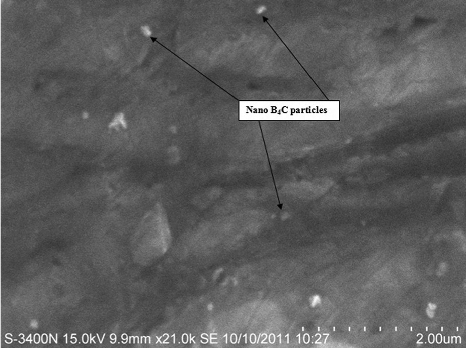
SEM micrograph of Al 7075 reinforced with 0.5 wt% of B4C.
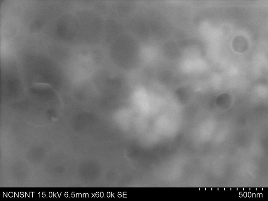
FESEM micrograph of Al 7075 reinforced with 0.5 wt% of B4C.
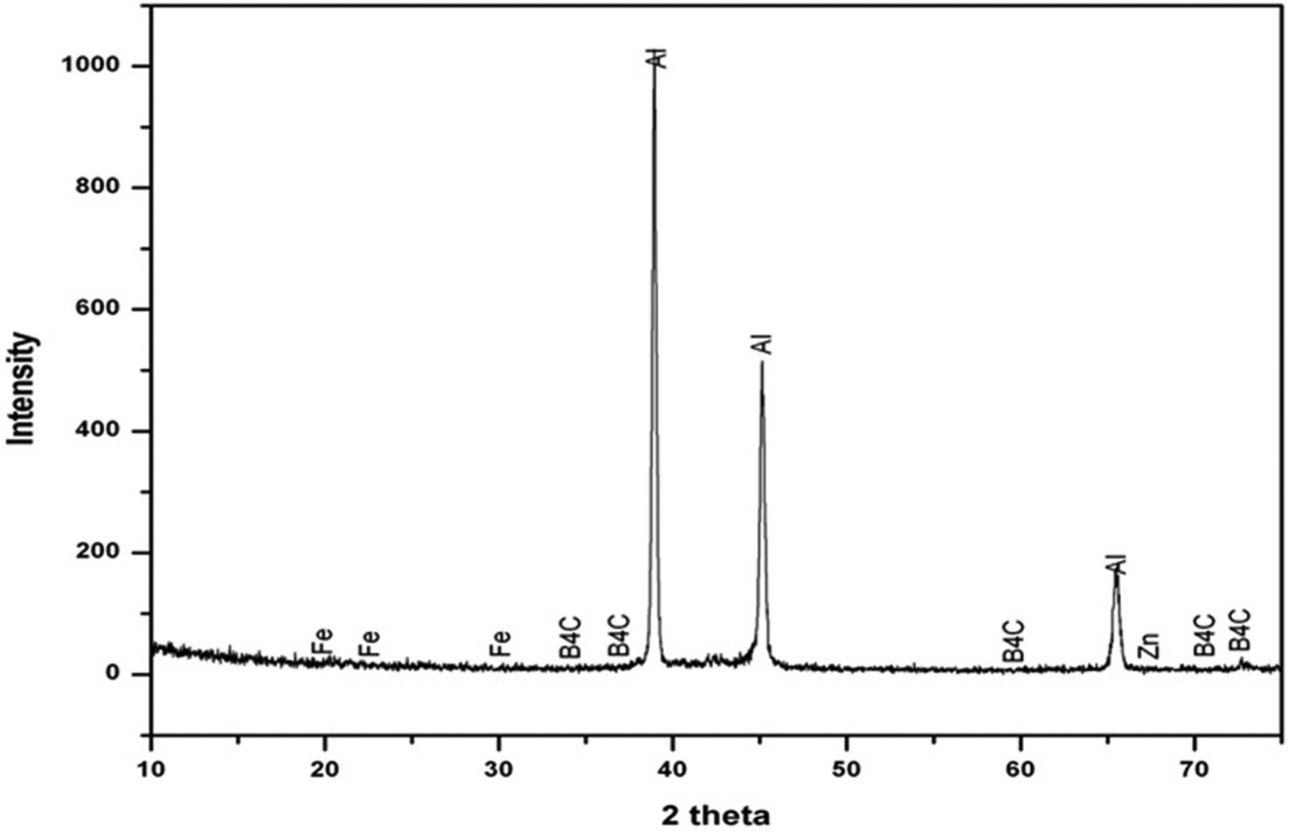
XRD analysis of Al 7075 reinforced with 0.5 wt% B4C nanocomposite.
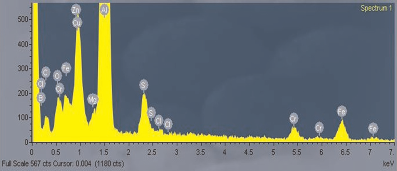
EDS analysis of Al 7075 reinforced with 0.5 wt% B4C nanocomposite.
To obtain the mechanical properties, tensile specimens with overall length of 100 mm, thickness of 6 mm and a gauge length of 32 mm were tested in UNITEK 94100 universal testing machine as per ASTM E8, which yields an ultimate tensile strength of 166.437 MPa and yield strength of 149.22 MPa, which are 52% and 34% greater than as cast Al 7075 alloy, respectively. The hardness of the samples was measured using a UHL Vickers microhardness measuring machine by applying a load of 0.5 kg, and this load was applied for 20 s yielding 124.8 HV, which is greater than 96 HV of as cast Al alloy. Similarly, reduction in percentage elongation is very less while comparing with as cast Al 7075 sample and within a reasonable range. In a way, not only mechanical properties have been improved by adding small quantity of nanoparticles but the ductility of the material has been retained. 19
EDM studies
Experimental procedure
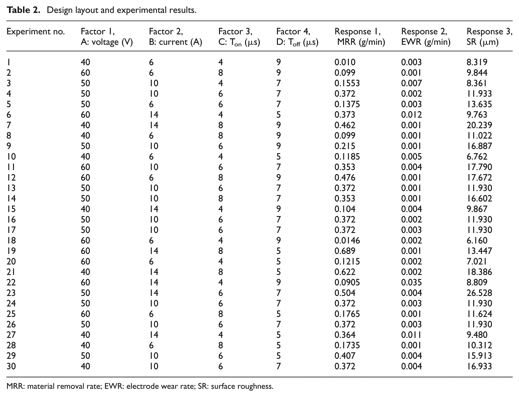
The experimental plan adopted in this study in the coded form is shown in Table 2. The experiments were performed on a die-sinking EDM of type Grace D-6030S and carried out for 20 min to acquire a more accurate result. Work materials of size 20 mm diameter and 30 mm thickness and electrolytic copper electrode of 10 mm diameter were used. The circular electrode is preferred over the other shapes of electrodes because it provides higher MRR and lower EWR. 20 Commercial-grade kerosene was employed as the dielectric fluid, and impulse jet flushing system was used to flush away the eroded materials from the sparking zone. The MRR and electrode wear values have been calculated by weight difference of the workpiece and electrode material before and after the machining using a digital weighing scale of 0.001 g precision.
Design layout and experimental results.
MRR: material removal rate; EWR: electrode wear rate; SR: surface roughness.
The machining was based on performance criteria selected for this study, which were based on performance characteristics such as MRR, EWR and SR 21

where wjb and wja are weights of the workpiece before and after machining, respectively, and t is the machining time. EWR is expressed as the ratio of difference of weight of the tool electrode before and after machining to the machining time

where web and wea are weights of the tool electrode before and after machining, respectively, and t is the machining time. Percent electrode wear is calculated as the ratio of volume of material eroded from the tool electrode per unit time to the volume of material eroded from the workpiece at the same time.
The MRR and electrode wear values have been calculated by weight difference of the work material and the electrode before and after machining using a digital weighing scale and recorded. The average SR value Ra (µm) was chosen to assess the surface finish quality. The surface of material generated using EDM is composed of many microscopic craters associated with random spark discharge between the electrodes. The size of craters produced on the workpiece surface mainly depends upon the magnitude of discharge energy. When more energetic pulses are generated, they usually lead to a higher material removal, which forms a deeper cavity resulting in higher SR. 12 The SR measurements for the machined surface were performed with a Kosaka Surfcoder SE 1200.
Development of mathematical model for MRR, EWR and SR
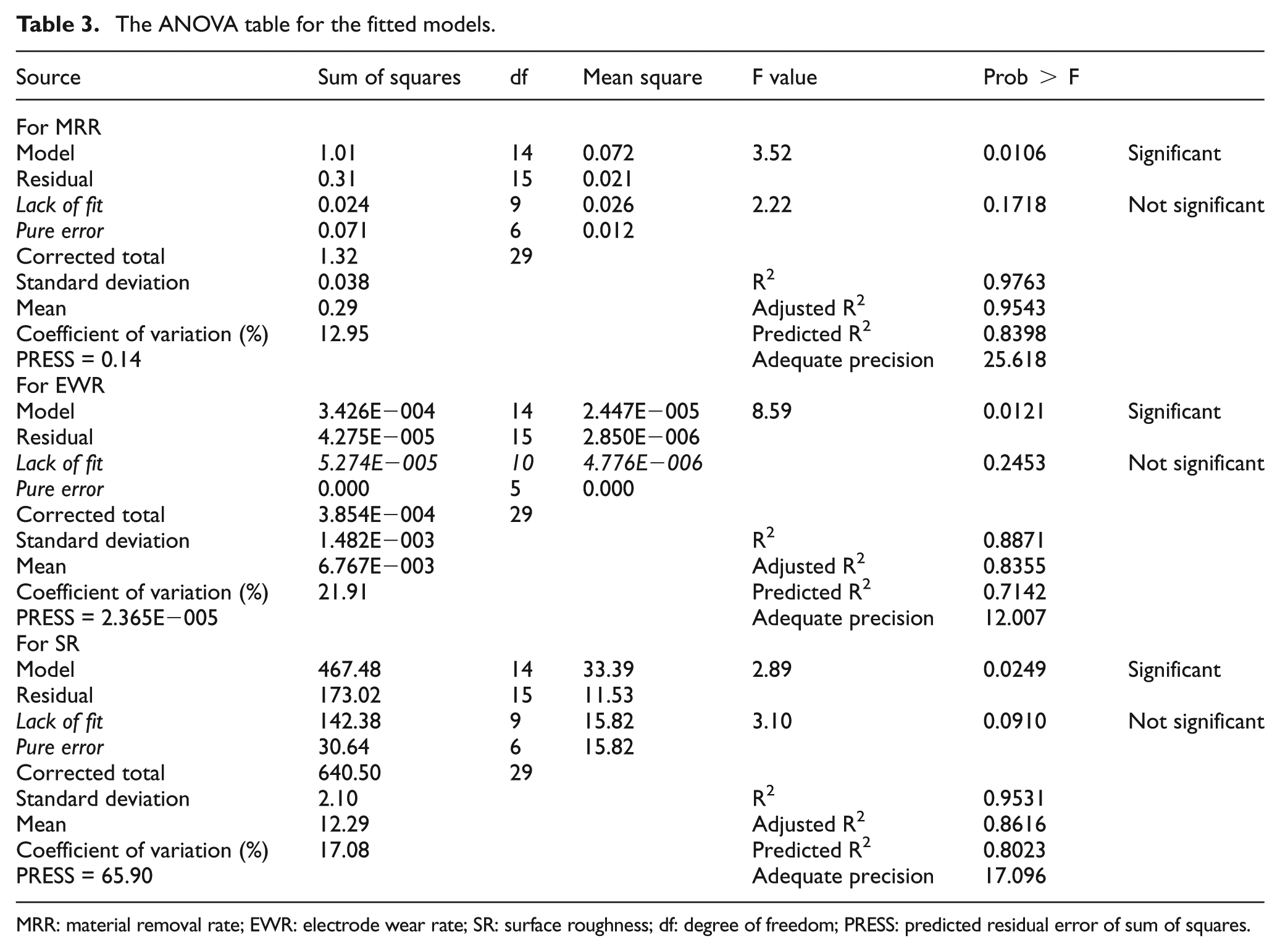
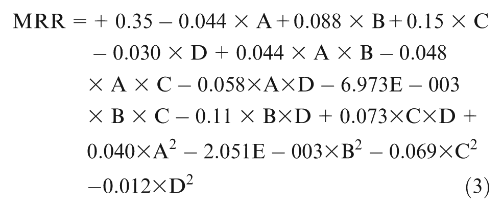
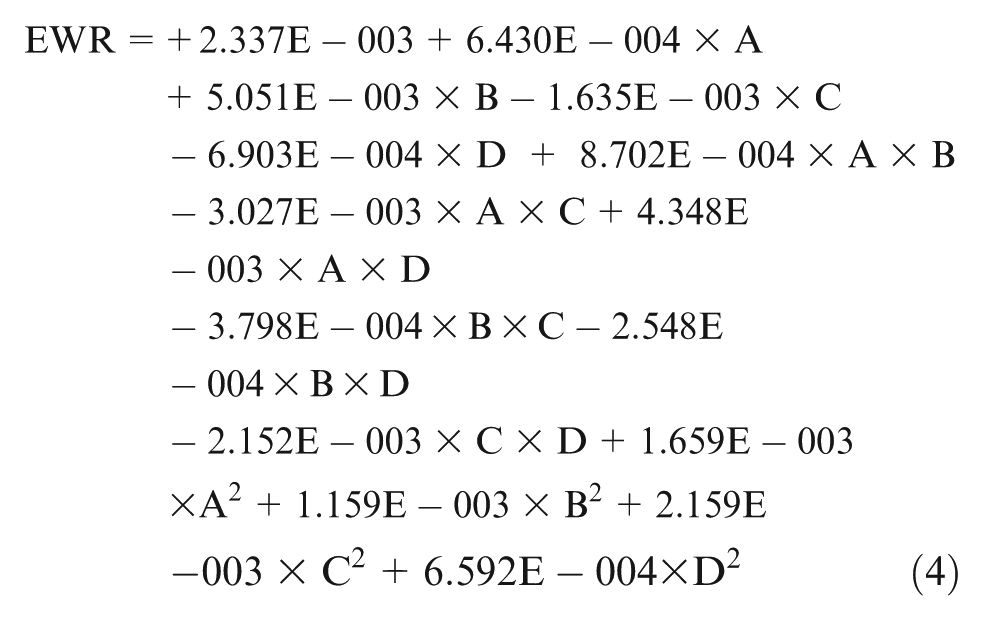
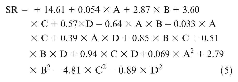
The fit summary recommended that the quadratic model is statistically significant for analysis of MRR and SR and the linear model for EWR. The results of the quadratic and linear models are given in the analysis of variance (ANOVA) Table 3. When R2 approaches unity, the response model better fits the actual data. There exists less difference between the predicted and actual data. Furthermore, the value of adequate precision (AP) in this model, which compares the range of the predicted value at the design point to the average prediction error, is well above 4. The values obtained are as follows: R2 = 0.9763 and AP = 25.618 for MRR; R2 = 0.8891 and AP = 12.007 for EWR; R2 = 0.8531 and AP = 17.096 for SR. The backward elimination process eliminates the insignificant terms to adjust the fitted quadratic models. These insignificant model terms can be removed, and the test of lack of fit displays no significance as desired. The final response equations for MRR, EWR and SR are as follows
The ANOVA table for the fitted models.
MRR: material removal rate; EWR: electrode wear rate; SR: surface roughness; df: degree of freedom; PRESS: predicted residual error of sum of squares.
Effect of process variables on the output parameter
MRR
Figure 6 shows the estimated response surface for MRR in relation to the design parameters of voltage, pulse current, pulse on time and pulse off time. The discharge energy was normally smaller when the pulse current was smaller; hence, the smaller discharge energy delivered into the machining zone was associated with a lower MRR; therefore, the machined cavity was shallower and the debris was more easily expelled from the machining zone. In contrast, if higher peak current is set, then the discharge energy is also higher. Therefore, deeper cavities have been formed. However, if the cavity depth increases, it causes difficulty in expelling the debris from the machining zone. It requires larger duration of pulse off time as shown in Figure 6(c), which agrees well with earlier findings. 11 Nevertheless, shorter pulse off time reduces the debris removal time; hence, the debris does not allow the electrical discharge to contact the workpiece. Due to this effect, a short-circuit is caused, which results in lower MRR. Therefore, the optimal values of process parameters are essential to obtain maximum MRR.
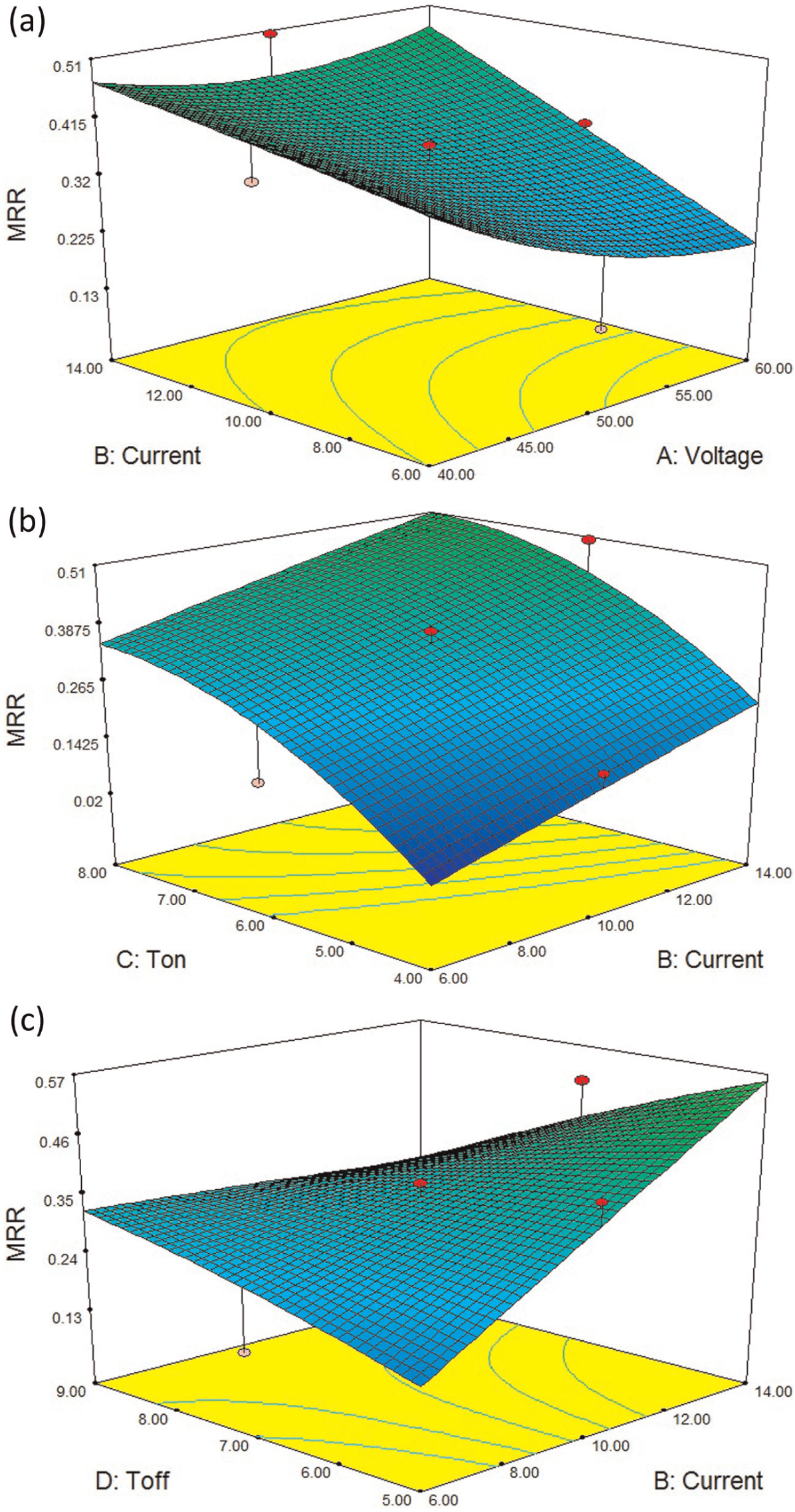
(a)–(c) Estimated response surface for MRR in relation to the design parameters of voltage, pulse current, pulse on time and pulse off time.
EWR
The wear of tool electrode is a dynamic process, which is simultaneously influenced by different parameters with varying input values. While electrical discharges erode materials from both the tool electrode and workpiece, the cracked carbon from the dielectric fluid may be deposited on the surface of tool electrode, which protects them from further erosion. Generally, longer pulse duration, lower pulse current and shorter pulse off time tend to increase the possibility of carbon deposition on the electrode surface, which helps to minimize the electrode wear. The electrode wear is low at smaller current; hence, shorter pulse off time is sufficient for the dielectric to restore its dielectric properties with minimum thermal loss. 22 As the eroded cavity was shallower, the debris can be easily flushed away from the machined zone and the same is reflected in Figure 7. The estimated response surface for EWR in relation to the design parameters of voltage, pulse current, pulse on time and pulse off time is shown in Figure 7. As can be seen from Figure 7(b), the EWR increases considerably with increase in pulse current and pulse on time. The EWR is more at higher values of Ton and Toff and also increases with respect to pulse current.
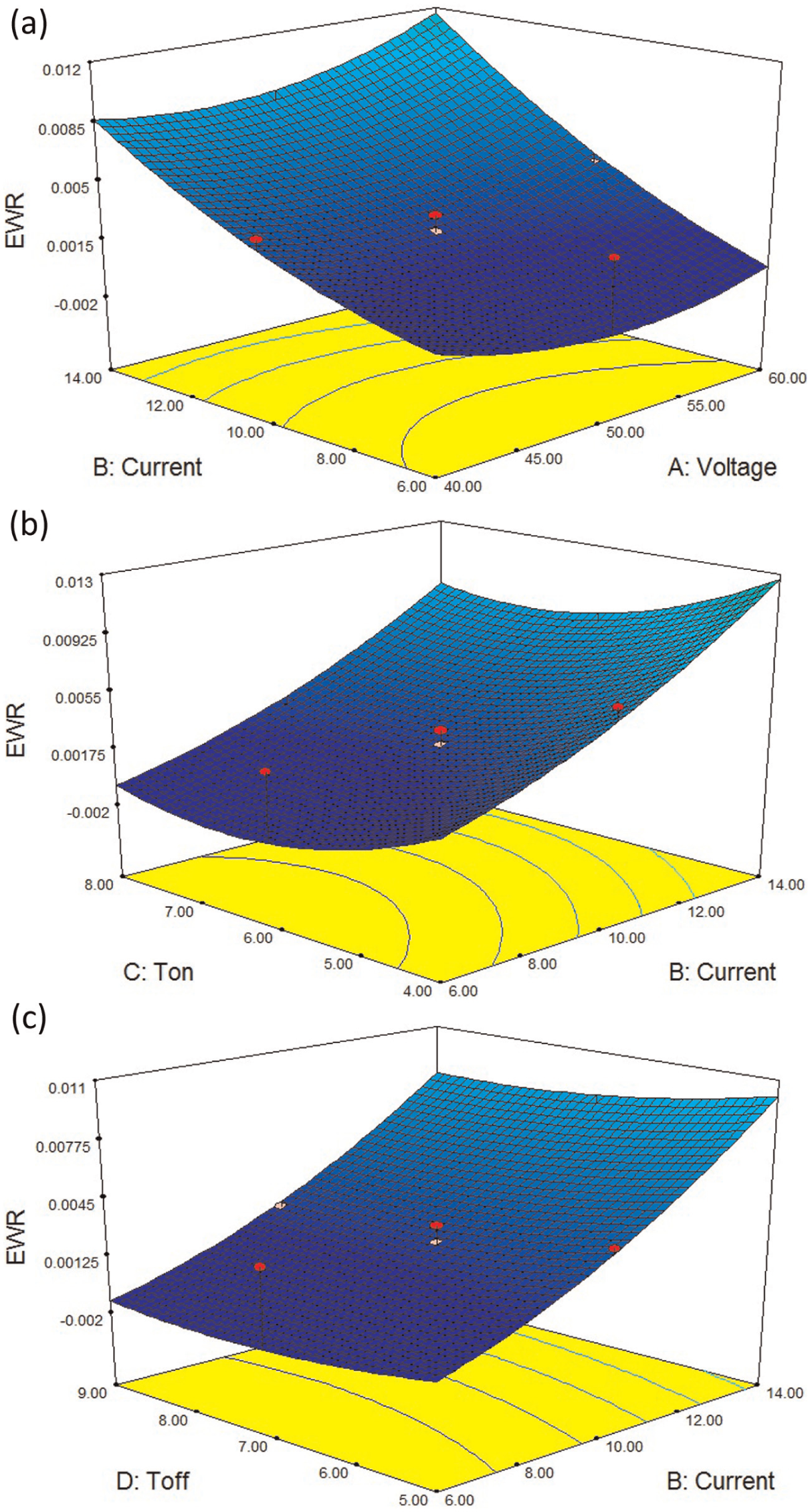
(a)–(c) Estimated response surface for EWR in relation to the design parameters of voltage, pulse current, pulse on time and pulse off time.
SR
In case of SR, the most influencing parameters are pulse current and pulse on time. When any one of this parameter is increased, it enhances the SR value. The high-energy pulse produces crater on the machined surface, which leads to poor surface finish quality.23,24 The estimated response surface for SR in relation to the design parameters of pulse current and voltage is shown in Figure 8(a), pulse current and pulse on time in Figure 8(b) and pulse off time and pulse current in Figure 8(c). As can be seen from Figure 8, the SR tends to increase with increase in voltage and pulse current. The SR also increases with increase in pulse on time. This is due to their dominant control over the input energy.
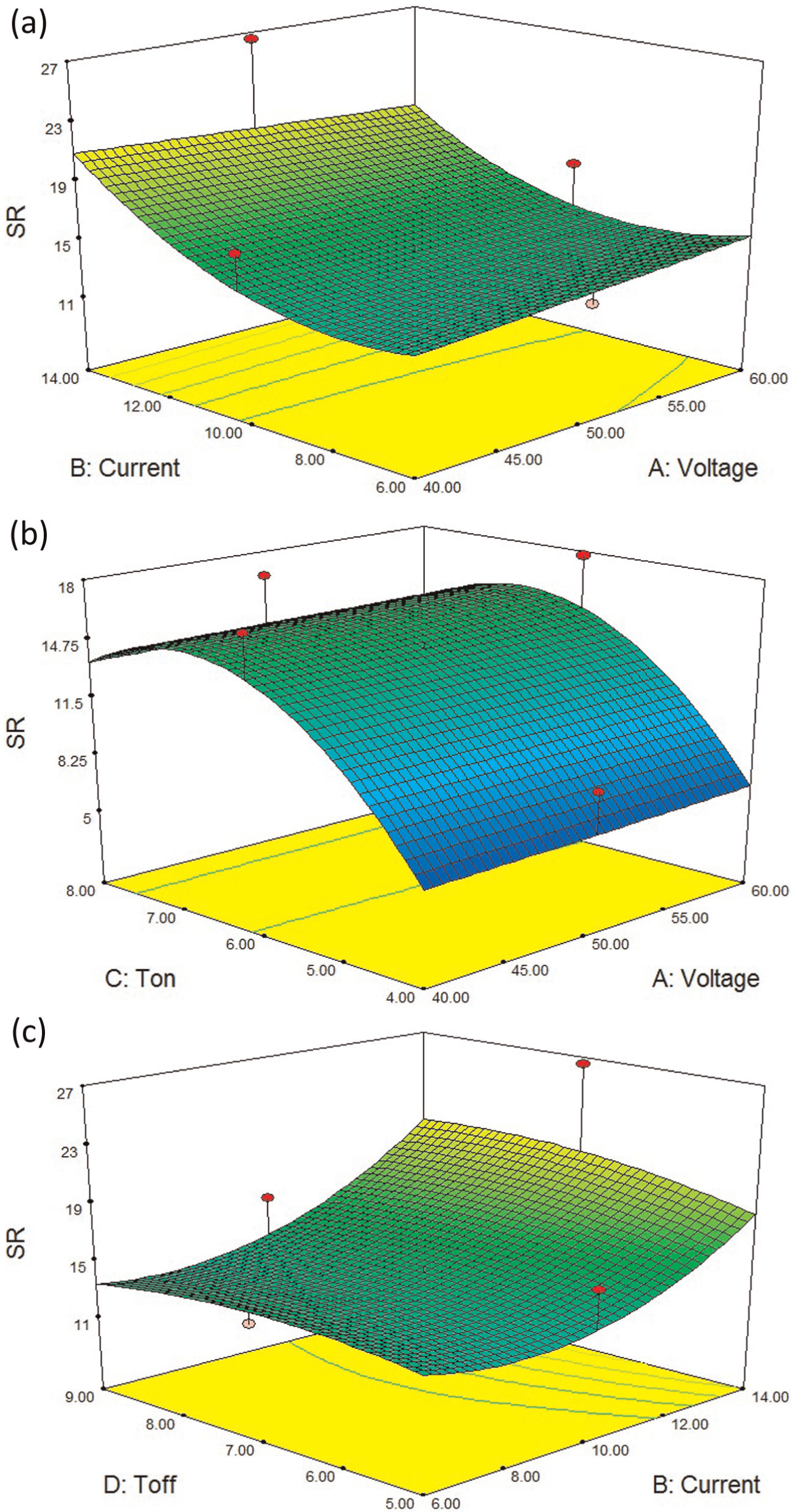
(a)–(c) Estimated response surface for SR in relation to the design parameters of voltage, pulse current, pulse on time and pulse off time.
Multi-response optimization
Selection of the optimal machining parameter combination for achieving improved process performance, for example, MRR, EWR and SR, is a challenging task in EDM operation due to the presence of a large number of process variables and complicated stochastic process mechanism. Based on Derringer and Suich multiple response method (desirability), the multiple quality characteristics were optimized. The method makes use of an objective function D(X) called the desirability function (utility transfer function) and transforms an estimated response into a scale-free value (di) called desirability.25–27 The factor settings with maximum total desirability are considered to be the optimal parameter conditions. Hence, the maximum total desirability obtained for this process is 0.798 as shown in Figure 9. This combination has been evaluated with the help of Design-Expert® software. Three responses, that is, MRR, EWR and SR, have been optimized simultaneously using developed models (equations (3) to (5)).
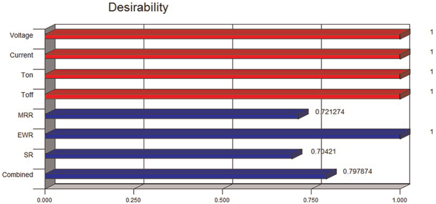
Bar graph showing the maximum desirability of 0.798 for the combined objective.
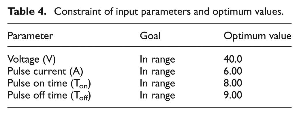
The optimum parameters of combination settings for maximizing MRR and minimizing EWR and SR are as follows: voltage: 40.0 V, pulse current: 6.00 A, pulse on time: 8.00 µs and pulse off time: 9.00 µs. The confirmation experiments were carried out for optimal process parameters in order to predict and verify the improvement of the performance characteristics. The results of confirmation experiment agree well with the predicted optimal settings. However, an error of 3.21%, 6.19% and 4.63% has been observed for MRR, EWR and SR, respectively, which confirms excellent reproducibility of the experimental conclusions given in Tables 4 and 5. Moreover, in order to observe the better resolution of the finished surface, atomic force microscopy (AFM) analysis was performed. 28 Figure 10 shows that lower crater height of the machined surfaces results in lower SR value.
Constraint of input parameters and optimum values.
Predicted and observed optimum values of responses.
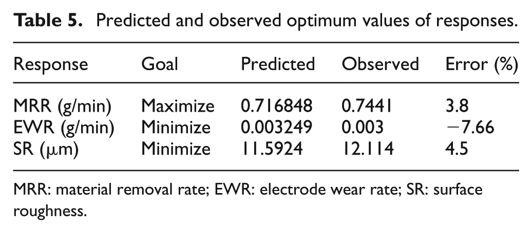
MRR: material removal rate; EWR: electrode wear rate; SR: surface roughness.
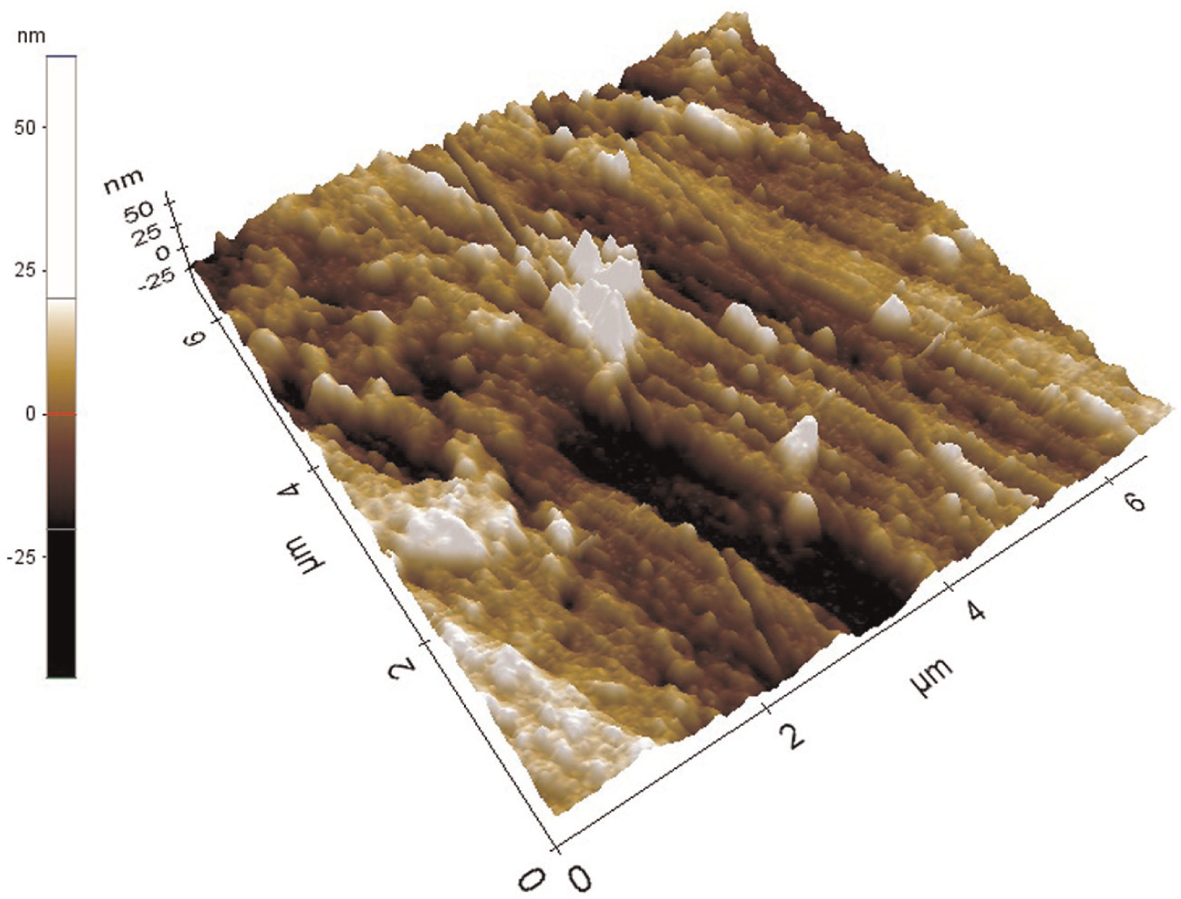
AFM image of the confirmation experiment.
Conclusion
The investigations of Al 7075 reinforced with B4C nanoparticles were studied for the EDM process, and the following observations were made.
Aluminium-based MMNCs reinforced with nanosized B4C particles were successfully fabricated in ultrasonic cavitation method. The nanoparticles are very well dispersed in the molted metal and give improved results.
The EDM of aluminium MMNC was successfully carried out using face-centred CCD of RSM by conducting 30 experiments for four factors at three levels.
The predicted values concur well with the experimental values, and this can be confirmed with the good agreement of R2 values of MRR, EWR and SR.
The two main significant factors that affect the MRR are pulse current and pulse on time. The MRR first increases with an increase in pulse on time and then decreases with further increase in pulse on time.
The pulse current and pulse on time have statistical significance on both EWR and SR. The higher pulse off time lower the EWR value.
The value of SR increases with increase in pulse current and pulse on time, whereas when voltage is concerned, SR decreases up to 50 V and then increases with a further increase in voltage.
The optimum parameters of combination settings for maximizing MRR and minimizing EWR and SR are as follows: voltage: 40.0 V, pulse current: 6.00 A, pulse on time: 8.00 µs and pulse off time: 9.00 µs. The results obtained would be very much useful and would serve as a technical database for aerospace/automotive industries.
Footnotes
Acknowledgements
The authors are very much thankful to Dr D. Nageswara Rao, Professor, Department of Mechanical Engineering, Andhra University, Visakhapatnam, India, for the help rendered to fabricate the material in the ultrasonic cavitation setup.
Funding
This research received no specific grant from any funding agency in the public, commercial or not-for-profit sectors.