
Abstract
The magnetic field distribution in magnetron sputtering processes has been verified to influence the collision of positive ions on the target, as well as the efficiency of the deposition onto the substrate. However, locally concentrated collision due to the distribution has also been known to lead to nonuniform erosion on the target, which deteriorates the efficiency of sputtering. In this study, a cylindrical magnetron sputtering system with a rotary-type target is proposed to improve the expected lifetime of the target by reducing the local erosion of target in the magnetron sputtering process. For the sputtering system, the magnetic field distribution over the target was analyzed with finite element method. Based on the analysis, the effect of the configuration of permanent magnets on the magnetic field distribution was investigated. The result of the analysis could be used to predict the region where concentration of positive ions occurs and thus to estimate the pattern of how the erosion on the target surface would occur for the proposed system. The results also reveal that the magnetic field distribution related to the erosion pattern could be controlled with the configuration of the permanent magnets.
Keywords
Introduction
Sputtering phenomenon has been widely applied to deposit various types of thin films on substrates with magnetron sputtering systems. It is used in application areas, including wear-resistant coatings, low-friction coatings, corrosion-resistant coatings, and coatings with specific properties such as large-area display panels. 1
In sputtering systems, energetic particles collide with a target, which emits atoms that are deposited onto a substrate. The sputtering process consists of three steps, which are the acceleration of ions, the bombardment of ions on the target, and the emission of atoms from the target. The emitted atoms are deposited to form a thin film on the substrate. The processes include direct current (DC) sputtering, three-pole sputtering, radio frequency (RF) sputtering, magnetron sputtering, and so on. Magnetron sputtering systems were recently developed to significantly improve the efficiency of DC sputtering systems by placing permanent magnets behind the target. A schematic diagram of a DC magnetron sputtering system is shown in Figure 1. In the magnetron system, the magnetic field formed by the magnets confines the electrons from the target to a certain area, which increases the bombardment of positive ions on the targets, finally resulting in the improvement of the deposition efficiency on the substrate. In order to obtain further improvement of the efficiency, the target needs to be designed with various shapes. Magnetron sputtering with planar targets has been well studied with respect to magnetic field distribution. The magnetic field distribution has been analyzed with finite element method (FEM) 2 as well as analytically, 3 and traces of electrons in the chamber were studied with elapsed time. 4 In previous studies using magnetron systems with planar targets, it has been difficult to solve the problems associated with the uneven distribution of the magnetic field causing locally deep erosion, which shortens the lifetime of the target. However, the important problem of nonuniform erosion has not been well studied, and only a few studies have been performed on the change of magnetic field distribution with respect to the parameters of the sputtering process.1,5
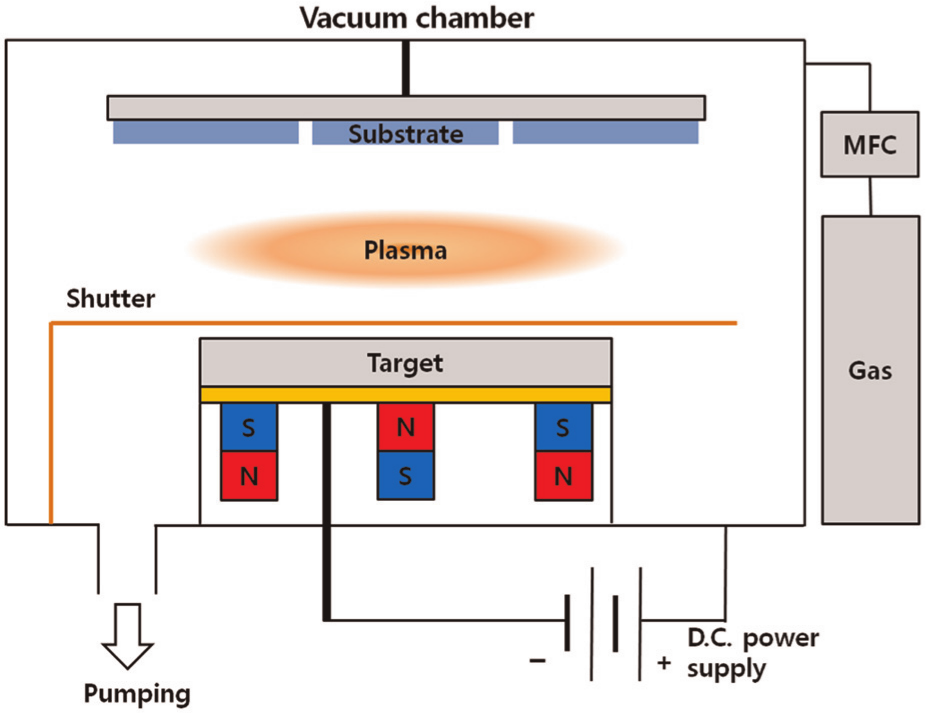
DC magnetron sputtering system.
In this study, a cylindrical magnetron sputtering system with a rotary target is suggested to manage the erosion problem of the target in the sputtering process and to subsequently improve the deposition efficiency of the process compared to planar targets. In the proposed system, the target rotates uniformly with a slow rate to expose new surfaces, before ions from the plasma deepen the erosion, while the gun system, which includes permanent magnets, is in a static state. The trajectory of positive ions following the electric field has already been analyzed for the rotary sputtering system, and an electric potential has been prescribed by a numerical method without considering the magnetic field effect. 6 However, it has been verified that the horizontal magnetic field parallel to the target surface clearly affects the collision of the positive ions driven by the electric and magnetic field forces, improving the sputtering from the target2,5 and revealing at the same time that the eroded area on the planar target is closely related to the magnetic field distribution. Therefore, the magnetic field distribution for the proposed system should be analyzed prior to predicting the performance of the sputtering process.
In this study, analysis on the magnetic field distribution was carried out to study the proposed system, using FEM. In addition, the effect of the configuration of the permanent magnets on the magnetic field distribution was investigated. The result is used to position the permanent magnets suitably to confine the movement of the electrons in a wider range over the target surface in the design of the sputtering system with a rotary-type target.
Analysis of magnetic field
Magnetic field between target and substrate
The magnetic field in a magnetron sputtering system can be developed between the target and the substrate in the chamber with the two different sources. The first source of magnetic field is permanent magnets located below the target. The second is attributable to the passage of the electrons from the target to the substrate by the electric field applied to the sputtering chamber. In this study, only the magnetic field distribution of the permanent magnets is analyzed, while the magnetic effect of the electric field was not taken into account to simplify the problem under the consideration of its negligible magnitude.
Electrons emitted from the target are enforced with the following Lorentz force applied by the electric and magnetic fields

where
When free electrons are forced to remain around the target for a long time while sustaining high speed, the density of the electrons increases. The accumulation of the electrons also enhances the probability of collisions between the electrons and gas particles in the plasma to generate positive ions, which ultimately bombard the target. Therefore, the efficiency of sputtering can be improved by increasing the amount of bombardment of ions on the target. When the forces acting on electrons are computed, traces of electrons can be predicted. Thus, suitable traces can also be decided to maximize the density of free electrons over the target surface. To solve the equation of the force, the magnetic field should be determined in advance. In this study, the magnetic field generated by the permanent magnets was analyzed using FEM.
Trajectory of electron in magnetic field distribution
The trajectory of electron in a sputtering system indicates where the plasma density increases over the target. Therefore, the influence of the distribution of magnetic field upon the shape of erosion on the target can be estimated with a simulation on the trajectory of electrons in a magnetic field distribution. For the purpose of this, the trajectory of electron in a magnetic field distribution was predicted for the sputtering system with a planar target for which the analytic solution on the distribution of magnetic field can be obtained. 3 When an electron is forced in the magnetic field by the Lorentz force as in equation (1), acceleration of the electron can be derived from the force in terms of mass and derivative of velocity. Because the magnetic density varies with the position in the magnetic field, the velocity of the electron can be found by a numerical integration using the Heun method. 7 The position of the electron can be then located with the velocity.
Finite element formulation for magnetic field distribution
The Maxwell equation describing a magnetic field in a magnetostatic situation such as in the magnetron sputtering process is presented as follows


where
The relation between the magnetic flux density and the magnetic field intensity can be expressed as follows for magnetic materials

where
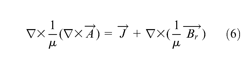
When magnetic vector potential

Then, the following relation is derived from equation (4)
With the principle of virtual work and the introduction of shape function N, the equation governing the magnetic field can be formulated for finite element analysis as follows 8
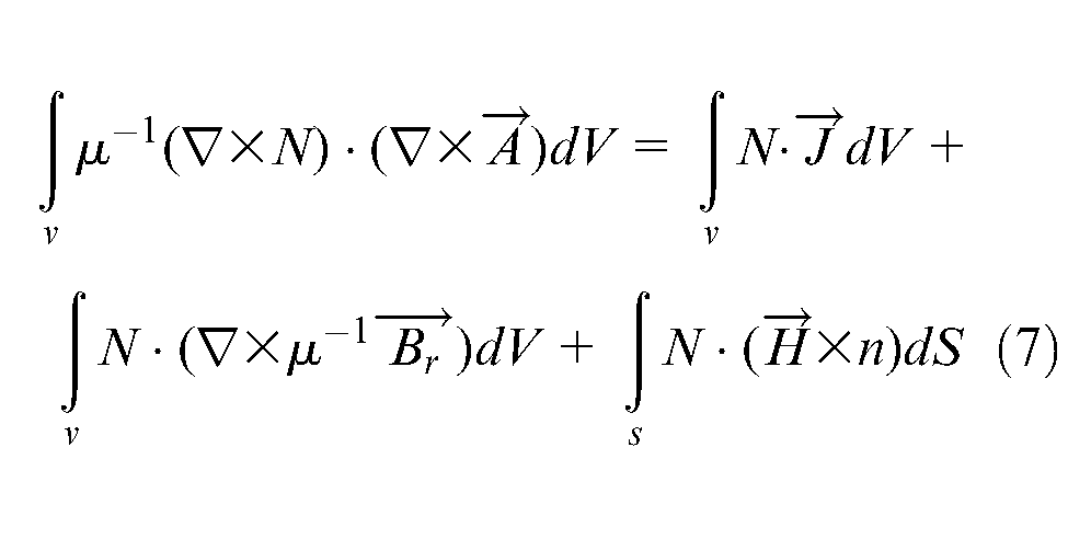
where n is the outward normal to a volume at the boundary S.
When the Curl operator G for xyz coordinates is introduced as follows
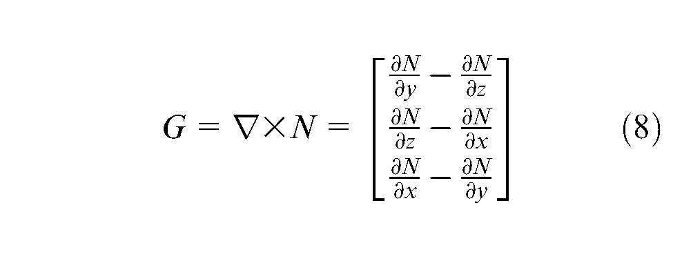
the finite element formulation for the magnetic field distribution can be obtained in a matrix formation as follows

where
Magnetic field in cylindrical magnetron system
In order to handle the uneven erosion problem in the sputtering system with a planar target, a cylindrical magnetron sputtering system with a rotary target is suggested as illustrated in Figure 2. The cylindrical target contains a stainless steel tube for cooling water flow, permanent magnets and a yoke located above the cooling tube, and a stainless steel cover to protect the magnets. The target is 1800 mm in length, 127 mm in outer diameter, and 9 mm in thickness.
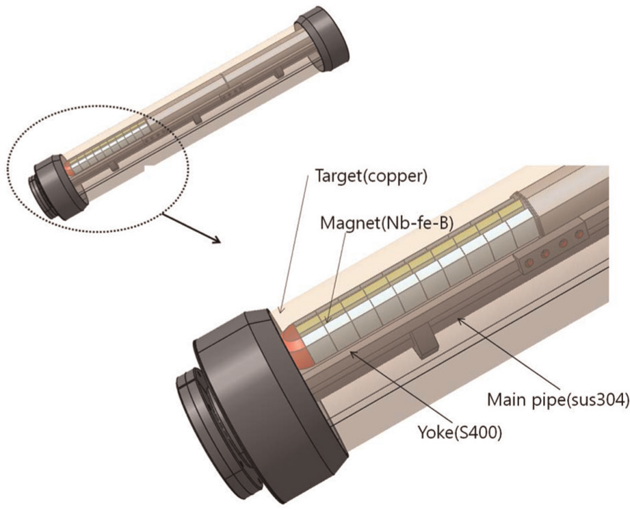
Cylindrical cathode system with a rotary target.
Sputtering occurs from the outer surface of the cylindrical target. The target is rotated slowly to keep its surface as flat as possible during the sputtering process before considerable erosion begins to occur on its surface. Since the length of the cylindrical system is much larger than the other dimensions, the magnetic field distribution and erosion are assumed to be uniform along the length direction of the sputtering system. Based on the assumption of uniform distribution of the magnetic field, only a two-dimensional analysis of magnetic field distribution was conducted at a middle section positioned normal to the length direction. Figure 3 shows the middle section of the system. The model corresponding to the section to be analyzed is shown schematically in Figure 4, which is located on the xy plane with the origin at the center of the target. The permanent magnets in the system consisted of north polar magnet 1 in the middle, south polar magnet 2 on the left side, and south polar magnet 3 on the right side, which are symmetrically positioned with the y-axis. The analysis was carried out with a Cartesian coordinate system, while the results of the analysis are presented in cylindrical coordinates for the convenience of expression and ready understanding.
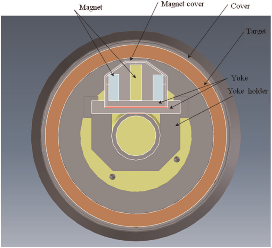
Middle section of cylindrical cathode system.
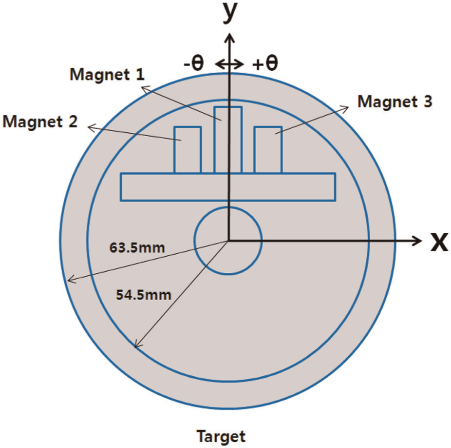
Two-dimensional coordinate system for the middle section of the cathode.
In the calculation of the magnetic field, the permeability should be given for each magnetic material. Since both the stainless steel for the cooling tube and the cover and the copper for the target have a permeability similar to vacuum, 9 the permeability for the materials was assumed to be 1.26 × 10⁻⁶ T m/A, which is the same as that of vacuum. For the yoke made of a carbon steel, a permeability of 1.26 × 10⁻³ T m/A was used for the calculation of the magnetic field. The permanent magnet was set to have a remanence of 1.0 T (10,000 gauss).
The solution domain was divided as shown in Figure 5. For the finite element analysis, the commercial software package program MARC was utilized. In order to find the proper placement of the permanent magnets to yield a minimum amount of uneven erosion, analyses on the magnetic field distributions were performed for three different arrangements of magnets in the cylindrical target, as shown in Figure 6. The configurations of the magnets were selected to be available for the practical design.
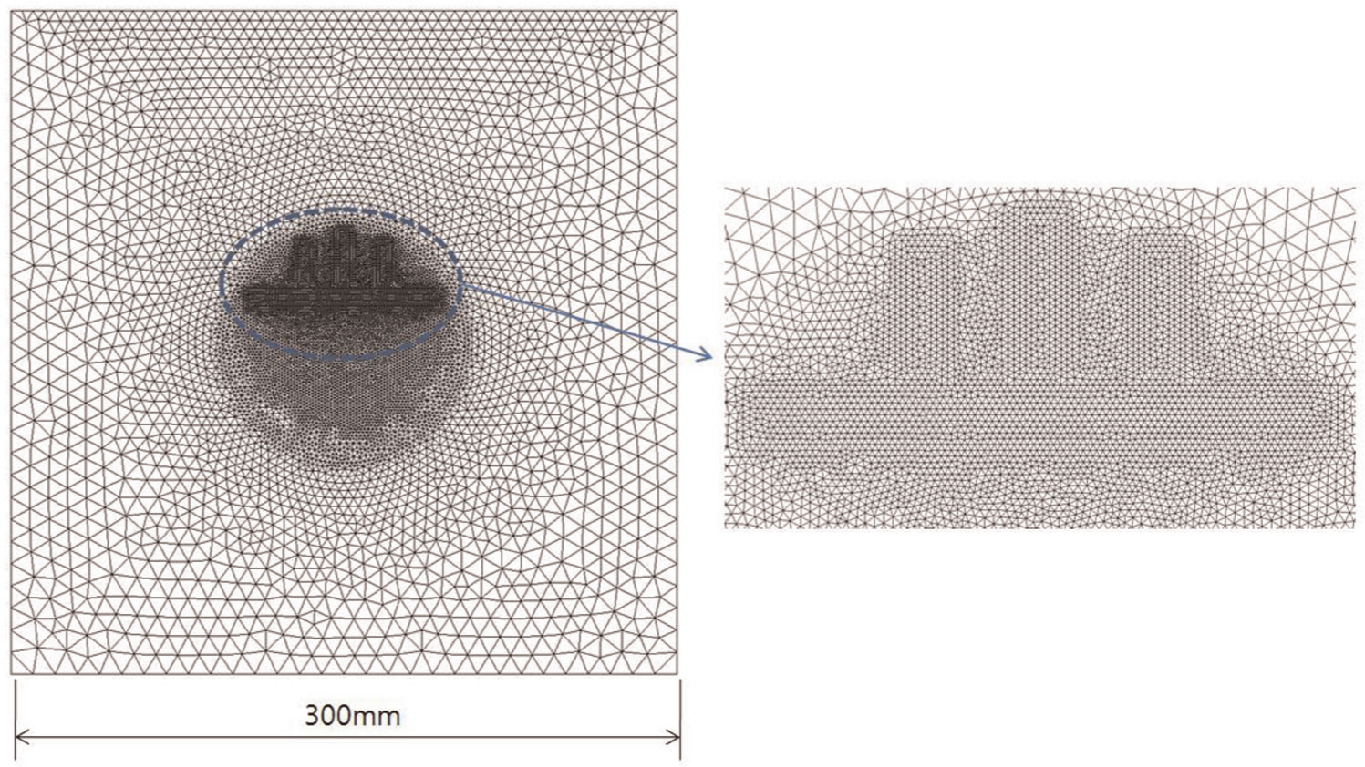
Mesh generation in solution domain for FEM analysis.
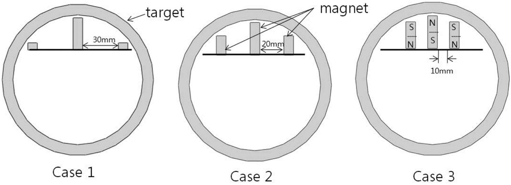
Three types of permanent magnet configurations.
Results and discussion
Trajectory of electron in magnetic field distribution
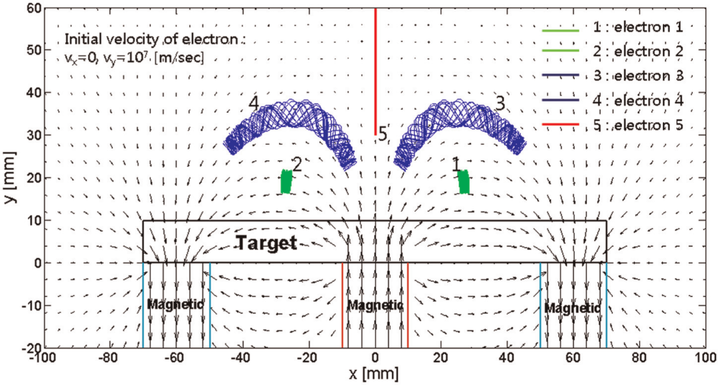
Figure 7 shows the trajectory of electron in a magnetic field distribution predicted for the sputtering system with a planar target using a numerical solution. The arrow represents the magnetic flux density, which is a vector indicating the direction with its head and the magnitude with its tail. The magnetic field distribution over the upper surface of the target has vertical direction at the magnet positions, while it is parallel to the target surface in between the magnets. In particular, the region with the parallel distribution of magnetic field becomes wider as the location get closer to the upper surface of the target. The trajectories of five particles were illustrated in the magnetic field. When the electrons moved initially at position 1 (25.7 and 20 mm), position 2 (−25.7 and 20 mm), position 3 (35 and 33 mm), and position 4 (−35 and 33 mm) with a velo city of
Trajectory of electron in magnetic field distribution of planar target.
Especially, the electrons at the positions 1 and 2 moved back and forth being confined at much narrower regions than those at the positions 3 and 4. This is because the velocities at position 1 and 2 are much closer to perpendicular to the direction of the magnetic field than those at the positions 3 and 4. A previous study also revealed similar results. 2 Therefore, the magnetic field distributed parallel to the target surface is verified to cause the electrons to be confined to a narrow region. The accumulation of the electrons consequently increases the plasma density, which directly affects the degree of erosion on the surface of the target.
Magnetic field distribution in cylindrical magnetron system
The magnetic flux density and magnetic field intensity in the solution domain of the sputtering system with the rotary-type target of case 3 shown in Figure 6 were predicted as shown in Figure 8, without rotating the target. The results indicate that magnetic fields between each two magnets of south and north polarity are formed symmetrically, presenting hundreds of gauss in magnetic flux density. The flux density on the lower surface of the target is shown to be the largest, and it decreases with the distance from the target along the y-axis. On the upper surface of the target, the magnetic fields appear to be distributed nearly parallel to the target surface. In particular, the direction of the magnetic flow over the target surface in the middle of each two magnets of south and north polarity is nearly perpendicular to the direction of the electric field between the target and the substrate. Based on the result, it would be expected that the electrons moving toward the substrate from the target with the perpendicular magnetic flux obtain rotational movement, making them stay around the surface of the target by the Lorentz force, while acting along the other perpendicular direction. Therefore, the electrons are supposed to be trapped within the region to increase the positive ions coming from the gas flow in the chamber.
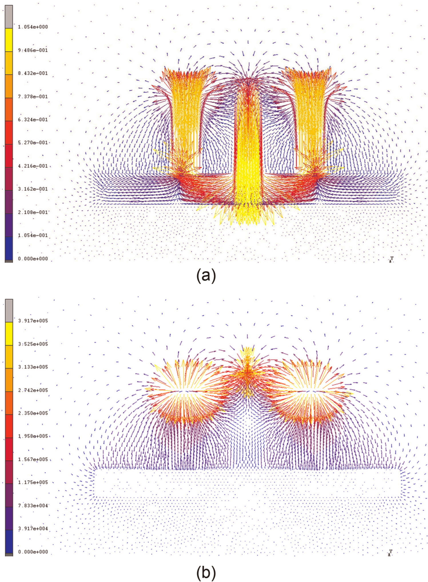
Magnetic field distribution in the solution domain: (a) distribution of magnetic flux density (B, (T)) and (b) distribution of magnetic field intensity (H, (A/m)).
The magnetic flux density obtained along the circumferential direction on the upper surface of the cylindrical target of case 3 is shown in Figure 9. The magnetic field can be divided into directional components. The magnetic flux density B can be divided into Bn in the radial direction and Bt in the circumferential direction. The circumferential component Bt of the magnetic flux density directly influences the movement of free electrons and thus enhances the density of the electrons in a confined region, increasing the number of ions that bombard a certain area of the target. Therefore, when the absolute magnitude of Bt increases in a region, the region begins to erode locally corresponding to the increment. According to the result shown in Figure 9, when the target is located in a static position without rotation, the erosion is expected to increase from 0° to 13° and decrease from 13° to near 30°, followed by an increment of erosion to near 30° and a slow decrement at further angular positions. Thus, uneven erosion is to be profoundly produced on the target surface when the target system is not rotated.
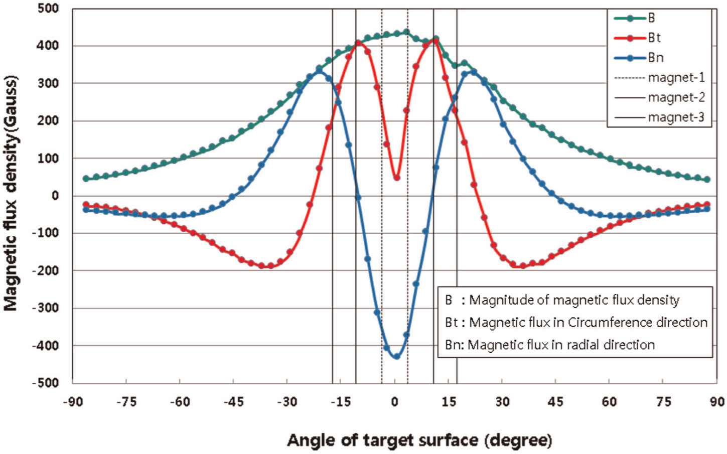
Magnetic flux density (B) on the upper surface of target.
Effect of magnet configuration
In order to find a proper placement of the permanent magnets for flatter and broader erosion instead of uneven erosion, analyses of the magnetic field distributions were performed for three different arrangements of magnets with the cylindrical target. The results of the analyses are presented in Figure 10 with the magnetic flux density on the upper surface of the target for each placement of magnet.
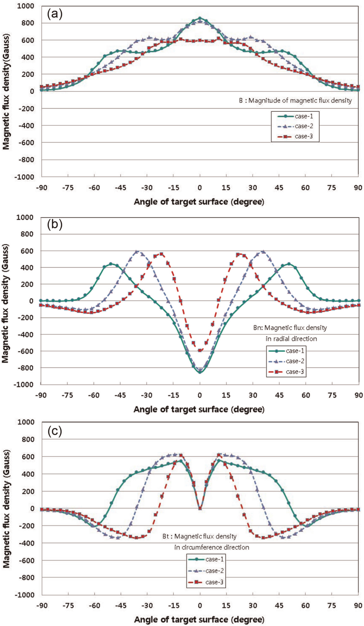
Magnetic flux density distributions on the upper surfaces in three different configurations of magnets: (a) absolute magnitudes, (b) radial components, and (c) circumferential components.
Figure 10(a) shows the absolute magnitude of magnetic flux density for each case of magnet arrangement. An insignificant difference in the absolute magnitude of magnetic flux density of hundreds of gauss was obtained between the arrangements.
The radial component of the magnetic flux density is presented in Figure 10(b) for each placement of magnets. Compared to other cases, the case 1 yielded the broadest distribution of magnetic flux density.
Figure 10(c) illustrates the circumferential component of the density for each of the three arrangements of the magnets. Since the component is perpendicular to the movement of electrons emitted from the target due to the electric field, the component of the magnetic field that is parallel to the target surface induces rotational movement of the electrons and accordingly enhances their density, followed by increase in the bombardment of ions on the target, deepening the erosion.
As a result, the erosion of the surface of the target would mainly be related to the distribution of the components. According to the illustration of the result, the erosion is estimated to increase from 0° to 13° and begins to decrease from 13° for every arrangement of the magnets. The result also indicated that in the case of far distance between magnets like in case 1, the magnitude gradually decreased from 13° but started to decrease rapidly from near 45°. When the magnitude changes rapidly, the eroded region is expected to become narrower to yield uneven erosion. Therefore, case 1 can be the best arrangement of magnets among the three cases. This also implies that the distance between the magnets should be as far as possible to reduce the unevenness of distribution of the erosion by making the magnetic field much flatter on the target.
Figure 11 shows the angle between the magnetic induction vector and the direction normal vector to the target surface along the circumferential direction for each arrangement of magnets (case 1, case 2, and case 3). The angle determines the direction of the Lorentz force and thus the rotation period of the electrons. As the angle approaches 90°, the force reaches its maximum to increase the rotation speed of the electrons. When the angle decreases, the movement of the electrons starts to be less dependent on the rotation. The angle distributions were predicted, in the result, to differ greatly as the distance between magnets varied. The direction normal vector to the surface indicates the direction of electron movement from the surface. Therefore, the erosion of the target would be increased when the angle becomes close to 90° because of the great increase in the electron density.
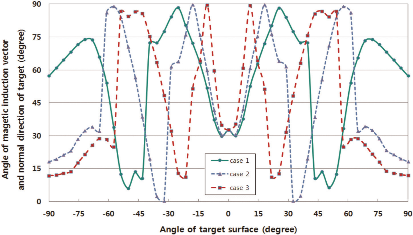
Angles between magnetic induction vector and normal direction of target surface in three different configurations of magnets.
Conclusion
The magnetic field distribution was analyzed using FEM for a cylindrical magnetron sputtering system with a rotary target. With the obtained results on the distribution, the region where the magnetic flux density changed rapidly could be distinguished. Since the region with the magnetic field distribution is closely related to the particular region confining the free electrons to increase the density, the result could be used to estimate the performance of the cylindrical system when the target had a static position. Moreover, according to the results of the analysis comparing the effect of the magnet configurations on the magnetic field distribution, the space between each of the permanent magnets below the target should be as wide as possible to make the magnetic flux density more uniform and thus to yield even distribution of the erosion of the surface. Therefore, the erosion would be reduced more significantly when the target is set to rotate to continuously expose new surfaces. When the space between the magnets became narrower, a higher but more uneven magnetic flux density was predicted in the circumferential component, which would make locally a higher sputtering rate and result in uneven erosion over the target surface with the lifetime of the target shortened. The result of the analysis can be used for the prediction of the trace of the free electrons, which affects the density of positive ions, which bombard the target and create erosion on its surface.
Footnotes
Funding
This research was supported by the Converging Research Center Program through the Ministry of Education, Science and Technology, Korea (2012K001247).