
Abstract
It is important in grinding for the fluid to remove heat from the grinding contact zone to avoid thermal damage to the workpiece surface and/or subsurface layers. The cooling effect of grinding fluid can be quantified by a convection heat convective heat transfer coefficient acting in the grinding zone. This article presents values of the convection heat transfer coefficient based on published experimental results for measured grinding temperatures. This article also presents a new convective heat transfer model based on principles of applied fluid dynamics and heat transfer. Predicted values for the convection heat transfer coefficient calculated from the model are compared with results from experiments obtained under a range of grinding conditions and with experimental data obtained from published literature. The results demonstrate that the new convection heat transfer coefficient model improves the accuracy of prediction and helps explain the variation in the value of convection heat transfer coefficient under varying process conditions. The results also show that convection efficiency strongly depends on the grinding wheel speed, grinding arc length and fluid properties. This new model can be readily introduced into current thermal models of the process used to predict and control grinding temperatures.
Introduction
Cooling by process fluids has an important influence on the removal of heat from the grinding zone and reduces the risk of thermal damage to the workpiece. The cooling efficiency is quantified by a convection heat transfer coefficient (CHTC) acting in the grinding zone. Heat is also removed from the grinding zone via conduction to the grinding chips, conduction to the wheel grains and conduction to the workpiece.1–3 Determination of the proportion of heat energy removed by each has been the subject of numerous studies in grinding thermal analyses.4,5 Convection to the fluid varies the proportions of heat available for distribution to other sinks, and hence, correctness in CHTC modelling is needed for accuracy in temperature prediction.
A model for the CHTC is developed based on applied fluid dynamics and heat transfer. The model is referred to as the laminar flow model (LFM). The effect of varying process conditions on the value of CHTC is investigated. The key parameters varied were depth of cut, wheel speed and work speed, fluid type and fluid delivery conditions, wheel type and diameter. The major process considered was plane surface grinding. Results of this analysis are compared with results obtained from experiments and case studies in the literature. The CHTC from case studies was obtained from inverse solution of the measured grinding temperatures reported and from application of a fluid wheel model (FWM). The LFM predicts lower CHTC values than the FWM and is described below in more detail. In the narrow range of maximum grinding temperatures between 110 °C and 165 °C, the experimental values of CHTC were closer to predictions from the LFM. However, this is the temperature range where boiling of water would be expected and could be a cause of reduced CHTC values. At lower grinding temperatures, higher values of CHTC were found.
Thermal studies
Thermal modelling is studied as a predictive process control tool6,7 to predict the grinding temperature. Control is exercised frequently in real time to avoid the risk or occurrence of heat damage to the workpiece.
Heat partition model
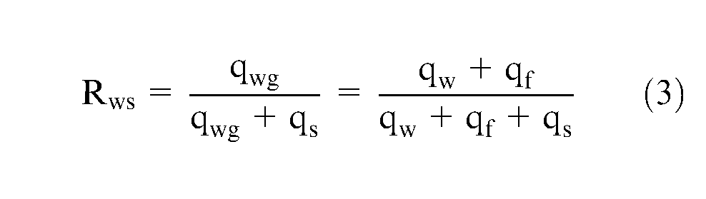
It is common for heat transfer to be expressed in terms of heat flux as this enables convenient calculation of conduction and convection quantities. The grinding total heat qt generated in the contact zone is distributed to four heat sinks: workpiece, wheel (abrasive), chips and fluid3,8

where
Flux values are defined as the rate of heat flow divided by the grinding contact area as follows. The grinding total heat, obtained from power or force measurement, is

where
Flux
Thermal model
From equation (1)

So that by equations (3) and (4)
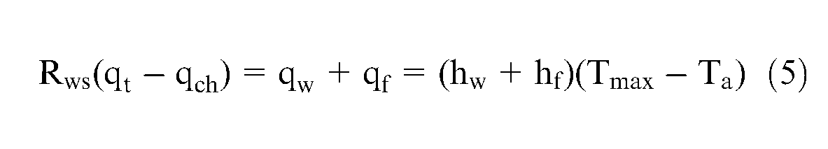
Then
where Tmax − Ta represents temperature rise above ambient. Tmax is taken to be the maximum background temperature rise in the grinding contact zone. Flash temperatures also occur at individual grain contacts that may be much higher than the background temperature rise. However, the area under the flash points is very much smaller, typically 1% of the total contact area. The grinding fluid is assumed to contact the entire grinding contact area. It is therefore the background temperature rise that is always employed for studies of fluid convection.
The work–grain partition ratio according to Rowe et al. 9 is expressed as
where
A conduction factor for the net heat flow into the workpiece

The factor C has a maximum value of 1.13 for a uniform heat flux distribution or 1.06 for a triangular heat flux, which is the preferred solution to match the distribution of material removal rate in the contact zone. The factor C is usually close to 1 for conventional work speeds and shallow cuts, 8 although lower values apply for deep grinding. 3
Heat to the chip is expressed as
where
Grinding arc length
In predicting the temperature of the workpiece, it is very important to determine the effective length lc of the heat source over which the energy transfers into the workpiece. It has been found that the real contact length in grinding for vitrified and organic bonded wheels is much greater than the geometric contact length, lg. Theoretical solutions for real contact length were derived by Rowe et al. 10
The real contact length can be expressed as
where
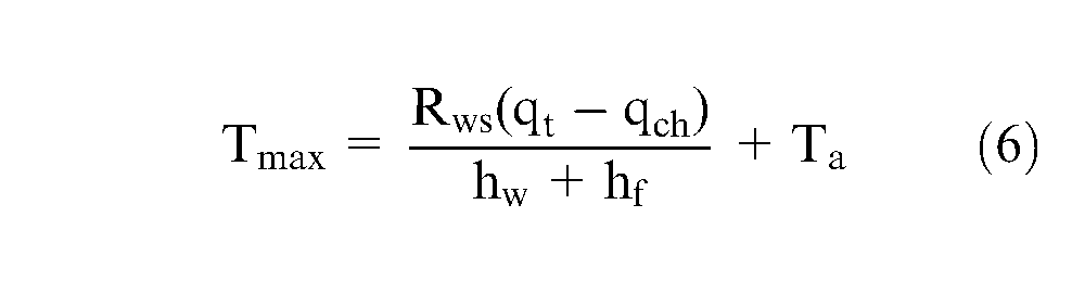
From equation (6), it is evident that the convection heat transfer hf is a critical variable of the process, and knowledge of its value is important for accuracy in workpiece surface temperature prediction.
Convection heat transfer model
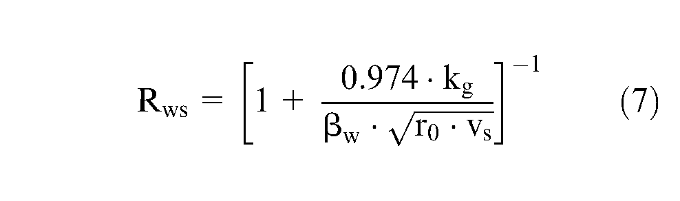
In earlier studies, Rowe et al. 4 estimated fluid convection based on an ‘FWM’. A key assumption in this case is that a layer of fluid covers the contact zone and moves across the work surface at wheel speed. The CHTC of the FWM based on the sliding heat source is expressed as

where the thermal property of fluid
Equation (11) suggests that the values of CHTC for fluid cooling depend on wheel speed, real contact length and thermal properties of the fluid. However, it is well known from theory of fluid dynamics 12 that the dynamic viscosity plays a role in convection, and this is excluded in equation (11). In the analysis of Lin et al., 13 a model to estimate CHTC was developed based on the same fluid dynamics and principles of heat conduction. However, in this case, conductivity was omitted.
A new analytical model for CHTC in grinding is proposed to include the following fluid properties: dynamic viscosity, conductivity, density and specific heat capacity. The aim of this work is to study and compare the predictive accuracy of the new model.
Achievable useful flow criterion
The flow of fluid through the grinding zone determines the cooling and lubrication efficiency. Useful flow is defined as the flow that actually enters the grinding contact area. Useful flow is lower than achievable if nozzle flow is low or if the jet is not well positioned. A method of calculating achievable useful flow is required to determine whether useful flow is high enough to remove sufficient grinding heat.
A method was proposed by Morgan et al.
14
for the calculation of achievable useful flow

where vs is the wheel speed, b is the grinding contact width,
Equation (12) can be used to predict the value of achievable useful flow for a given wheel and process. This can be used to give guidance on supply flow.
CHTC
If by application of the achievable useful flow criterion, the supply flow is sufficient to remove heat from the grinding contact area, assumptions can be made in order to simplify and facilitate the CHTC analysis.
For conventional operations, fluid velocity
As the flow drags on the workpiece surface, it is slowed at the wall to zero speed. When the fluid progresses in the grinding direction, the depth at which the fluid experiences a drag effect increases due to Newton’s law of viscous shear. The depth builds to a value that increases with grinding direction, and there is a laminar boundary layer. There are inaccuracies built into this physical representation, for example, the flow is almost certainly turbulent within the pores. However, for simplicity of comparison with experiments, the LFM is retained, and it is assumed that the fluid enters the grinding contact zone in a laminar stream. This is an approximation to the physical situation. In the following discussion, temperatures are given relative to ambient temperature for the sake of simplicity.
Assuming steady flow in the main stream at speed vs, speed at the wall is 0 and increases to vs at a distance δ from the wall. Similarly, temperature T increases from 0 at the wall and is assumed to attain a maximum Tmax at a distance δs from the wall, as shown in Figure 1. In the grinding situation, these boundary temperatures are reversed. The wall temperature in the grinding contact is the temperature Tmax, and the stream temperature Ts is assumed to be the ambient temperature Ta = 0. This does not affect the derivation of the basic equation.
Development of the flow speed and temperature boundary layers along a flat plate.
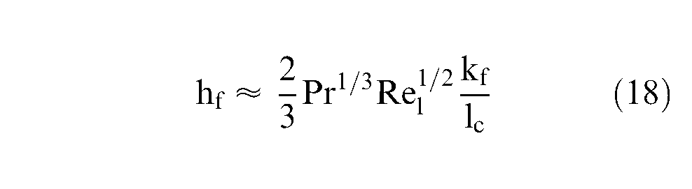
Heat transfer in steady laminar flow past a flat surface can be modelled as

In textbooks, the factor is given as 0.332 rather than1/3 = 0.333. The insignificant rounding is introduced here for convenience in the final expression given below as equation (19)


Assuming a constant wall temperature, the convection factor is
Therefore
The value of lc is the maximum value of x measured along the surface of the plate, that is, the grinding arc length. The wall temperature distribution in grinding arc length is not constant. An approximate expression for average temperature rise is
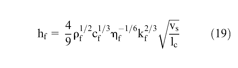
where the fluid properties are as follows: hf is the convection coefficient,
The factor 4/9 = 0.444 in equation (19). An almost similar model is obtained assuming an average heat flux along the contact zone rather than an average contact temperature. This assumption was mentioned by Lavine in a review of this article. The factor of 0.444 in equation (19) is then increased to 0.453.
Comparison of predicted CHTC with data from experiments
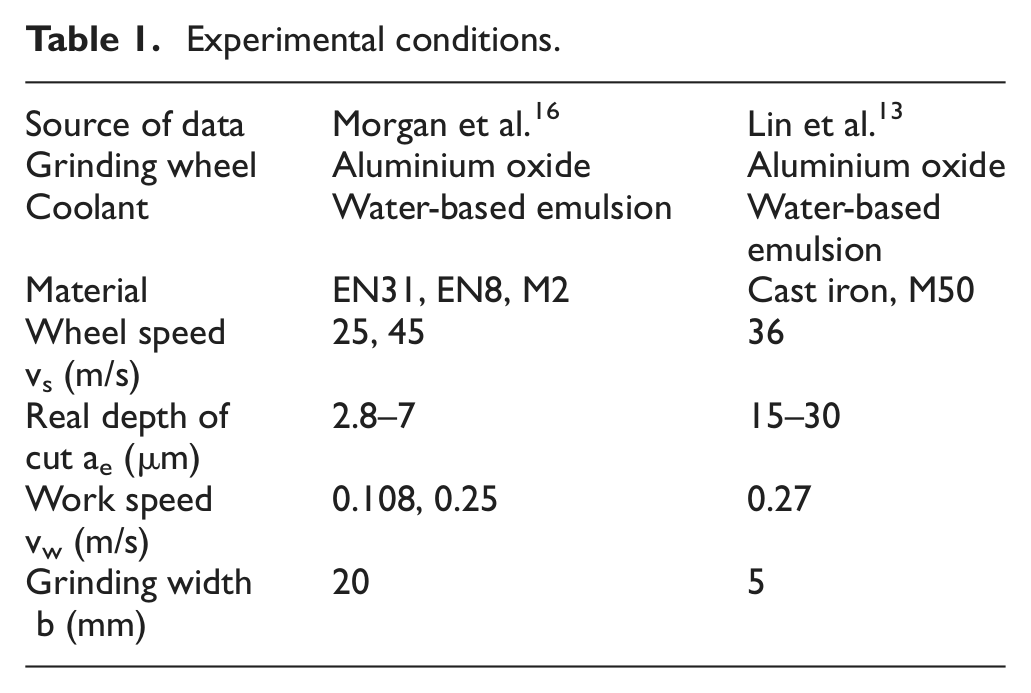
Experimental data from Morgan et al.,15,16 Barczak et al. 17 and Lin et al. 13 were entered into the CHTC model and also into the thermal model described above. The real contact length based on equation (10) is used for the thermal analysis. The experimental conditions are listed in Table 1. The thermal properties of steels (EN31, EN8 and M2), cast iron, water-based emulsion and abrasive are listed in Table 2.
Experimental conditions.
Thermal properties of materials
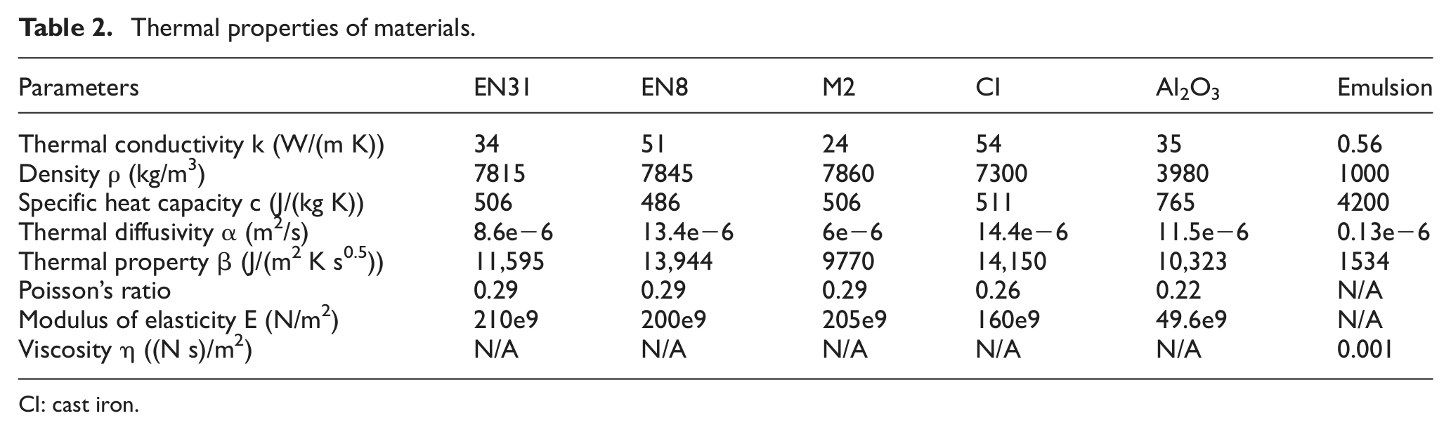
CI: cast iron.
Comparison of CHTC values with experimentaldata for water-based emulsion
A key aim of this study is to compare CHTC values calculated from both the newly developed LFM and the FWM with values obtained inversely using data from experiments (EXPT). This is achieved by matching the theoretical and measured grinding temperatures using equation (6) and published case studies data. The CHTC values calculated for the LFM and FWM and the value of CHTC (EXPT) for the cases of grinding cast iron and steel13,16 are given in Tables 3 and 4, respectively.
Calculated and experimental results of CHTC values.
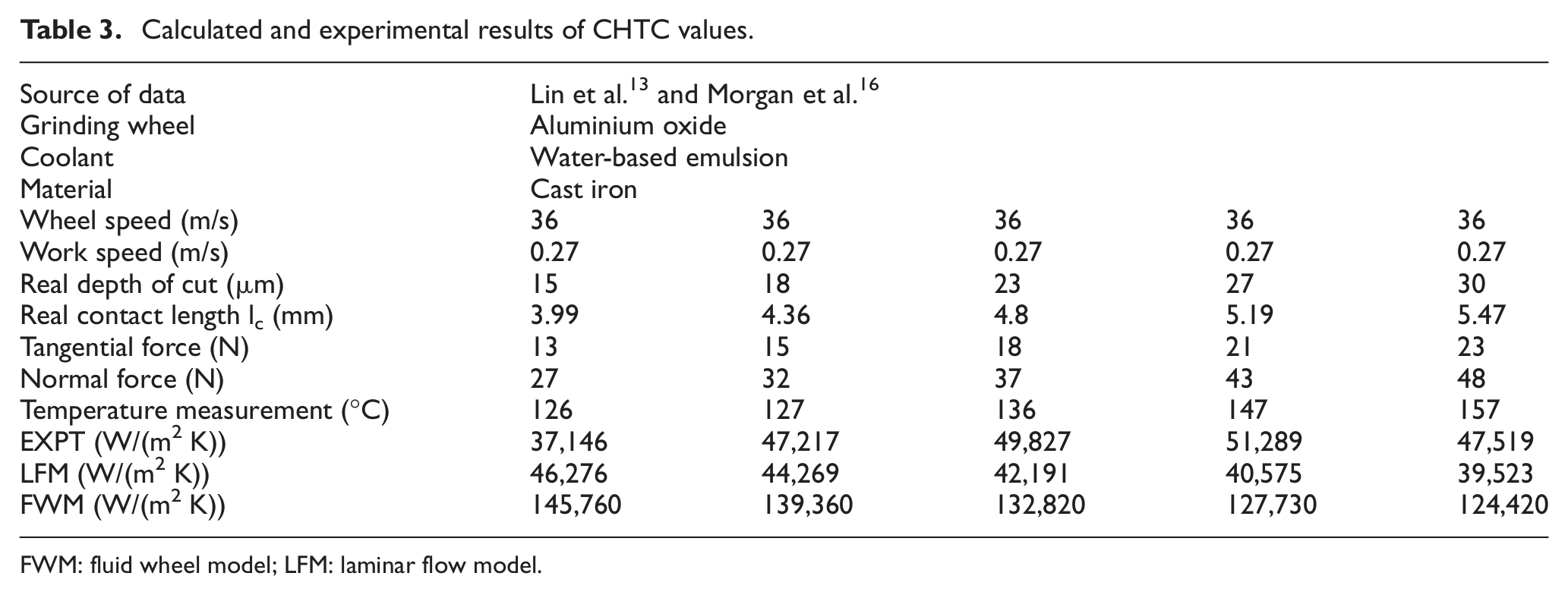
FWM: fluid wheel model; LFM: laminar flow model.
Calculated and experimental results of CHTC values.
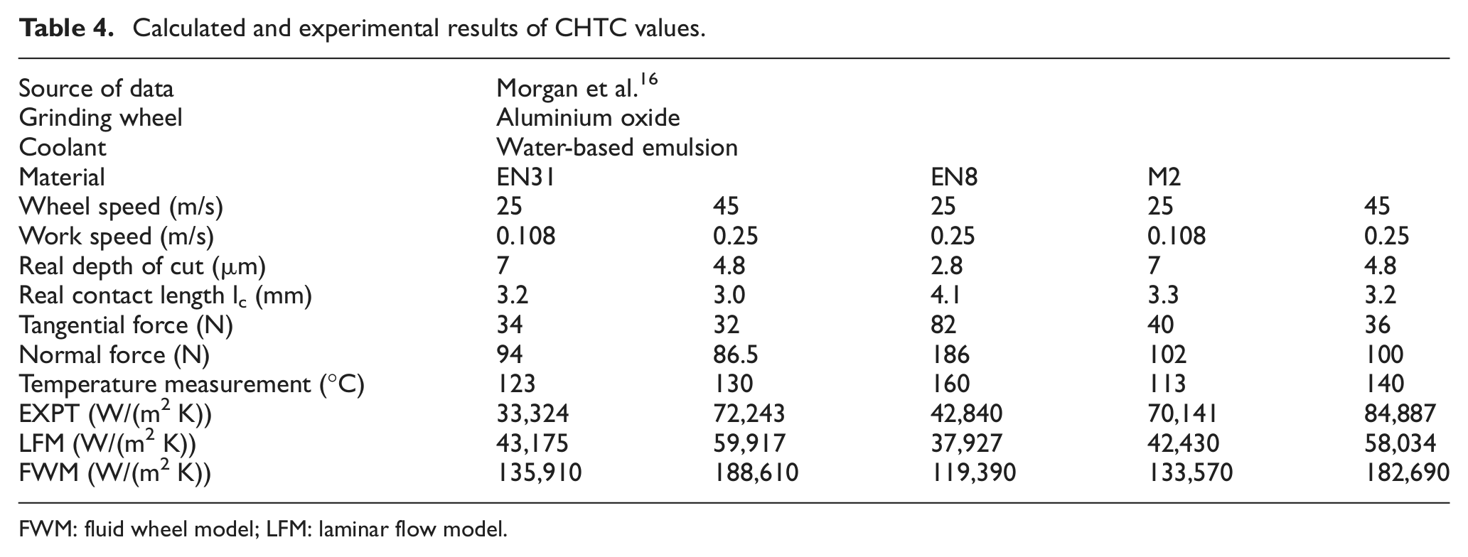
FWM: fluid wheel model; LFM: laminar flow model.
It is very interesting to note that taking the temperature measurement values to calculate the CHTC values (EXPT) for the water-based emulsion, the LFM exhibits better agreement than the FWM over the narrow range of conditions presented. In these conditions, the value of real contact length was 3 mm<lc<5.5 mm.
The values for CHTC (EXPT) are shown in Figure 2(a) with the predicted values of CHTC for the LFM and FWM. A linear fit is shown through each set of data points. For comparison with experimental results, temperatures are stated relative to 0 °C.
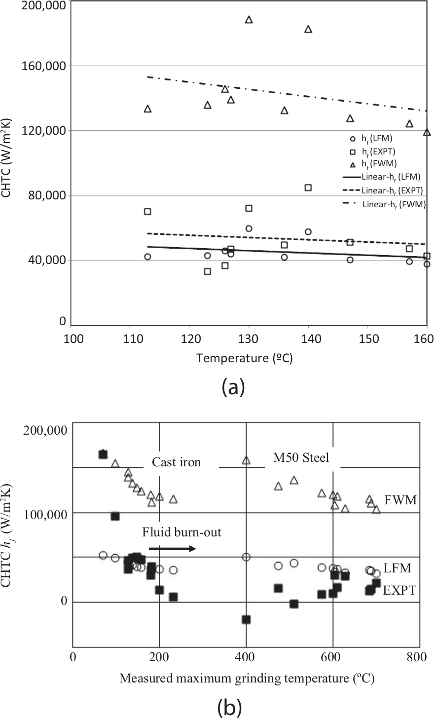
(a) Comparison of CHTC for EXPT, LFM and FWM. (b) Convection factors based on published 13 temperature measurements.
The values and trend line for the LFM agree better with EXPT than those for the FWM. It is evident in this range that convection is reduced as temperature is increased. The CHTC average value is approximately 60,000–70,000 W/m2. It is noted that the boiling of fluid can substantially reduce the cooling effectiveness when occurring at a threshold temperature.
Taking a wider range of temperatures, the agreement is less clear. Figure 2(b) shows results for cast iron and M50 steel. At higher temperatures, there is increased evidence of fluid burnout, and the CHTC reduces to approximately zero. This is expected of course. The thermal model requires that hf is made equal to zero to take account of fluid boiling at temperatures exceeding 180 °C. At low temperatures, it is possible that the CHTC value may be increased compared to the LFM line. However, it is suggested that this temperature range requires further research to test the accuracy of the measurements.
Effect of contact length on thermal predictionin LFM
Real contact length is an important factor in the calculation of grinding temperature. It is difficult to determine the real contact length in any given case as the theoretical models of contact length are derived employing a wide range of variables, the values of which are not available in most of the cases reported in the literature. However, the upper and lower limits of contact length can be analysed. In this context, two contact length values lc = lg and lc = 3lg are used to predict temperatures and to determine the limiting range for contact length wherein the values of CHTC predicted by the LFM correlate with CHTC (EXPT).
The predicted temperatures for the LFM using the two different contact lengths, lg and 3lg, are obtained from equations (6) and (19), and the results are shown in Figure 3. Most of the temperature measurements lie between the temperature predictions for contact lengths of lg and 3lg.
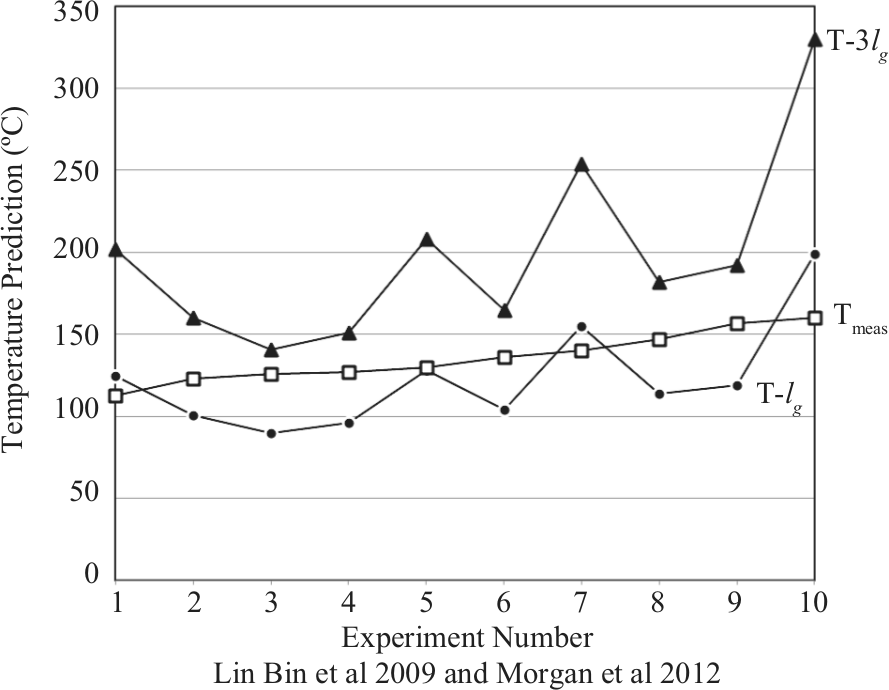
Measured and predicted maximum temperatures.
Case study comparing water- and oil-based grinding fluids
The following are typical calculations for water and oil coolants according to the two models for a wheel speed of 30 m/s and a contact length of 10 mm.
For water:
kf = 0.56 W/(mK), ρf = 1000kg/m3,cf = 4200 J/(kgK), ηf = 0.001 (N s)/m2
βf = 1600 J/(m2 K s0.5) and Gf = 510.5 J/(m2 K s0.5)
hf(FWM) = 87,700 W/(m2 K)
hf(LFM) = 27,960 W/(m2 K)
For oil:
kf = 0.14 W/(mK), ρf = 900 kg/m3, cf = 2100 J/(kg K) and ηf = 0.02 (N s)/m2
βf = 514.4 J/(m2 K s0.5) and Gf = 87.7 J/(m2 K s0.5)
hf(FWM) = 28,175 W/(m2 K)
hf(LFM) = 4804 W/(m2 K)
These values are of the right order of magnitude but rather lower than some experimental estimates based on temperature measurements given below.
Other published convection results for water- and oil-based grinding fluids
Values of convection factor obtained inversely depend on the thermal model employed. Other researchers’ results must be adjusted to match the particular thermal model employed.
Values of fluid convection factor have been estimated from grinding experiments and adjusted as follows. Rowe and Jin 18 reported average values of 290,000 W/(m2K) for water-based emulsions. Stephenson et al. 19 reported 23,000 W/(m2K) for neat oil. Applying adjustments for the difference in thermal model employed and the application of real contact length reduces these values to approximately 174,000 and 13,800 W/(m2K). More recent measurements by Jin and Stephenson 7 were for grinding 51CrV4 steel with a B252 cubic boron nitride (CBN) wheel at 0.4mm depth of cut. These values similarly adjusted to match the refined model in this article gave the following results:
Water-based (1): 104,000 W/(m2K) at 50 m/s wheel speed
Water-based (2): 144,000 W/(m2 K) at 50 m/s wheel speed
Water-based (3): 84,000 W/(m2 K) at 50 m/s wheel speed
Mineral oil: 26,200 W/(m2 K) at 50 m/s wheel speed
Mineral oil: 78,100 W/(m2 K) at 146 m/s wheel speed
Results were all obtained in grinding at temperatures well below fluid boiling. Unfortunately, insufficient data are available to conclude whether the new model is an improvement for oil fluids. However, experiments confirmed that the fluid convection factors depend on wheel speed as might be expected.
Conclusions
CHTCs of fluid in the grinding zone have been predicted through principles of applied fluid dynamics and heat transfer. The values of convection coefficient strongly depend on grinding wheel speed, grinding arc length and fluid properties. Experimental results show that the values of the CHTC can be high and of the order of 60,000–70,000 W/(m2 K).
The predicted CHTC values of the LFM showed better agreement than the values of FWM with experimental data in the region approaching fluid boiling. Contact length limits lg and 3lg can be used to provide boundaries on predictions of maximum grinding temperatures. The preliminary case study shows that the LFM is a useful analytical tool for prediction of the value of the CHTC in the grinding zone.
Footnotes
Funding
This study was supported by the Major State Basic Research Development Program of China (973 Program, grant number 2011CB706605).