
Abstract
Nanomeasuring machines are devices for solving various positioning and measuring problems in a range of several millimetres with sub-nanometre resolution. These devices are used for positioning, probing and measurements. The combination of this machine with a scanning force microscope leads to improved quality in the calibration of standards. The measurement accuracy and stability of the scanning force microscope are important for the achievable measurement uncertainty. Many systems are influenced by the creep, hysteresis and bending of the included piezo actuators. A scanning force microscope head with a combined deflection detection system that comprises an interferometer and a beam deflection system was developed. Due to this system, it is possible to simultaneously measure the displacement, bending and torsion of the cantilever with only one focussed beam. An additional high-speed piezoelectric actuator for the vertical motion of the cantilever was integrated and is controlled by the bending signal. The outcome of this additional control system is a much higher scan speed. The interferometer system can be used for precise measurement of the vertical cantilever motion. Hence, non-linearity and hysteresis in the actuator do not affect the measurement. The device was used for several calibration measurements on step height and lateral standards. This article deals with the set-up, function and application of a scanning force microscope head for dimensional metrology with the nanomeasuring machines.
Introduction
Nanopositioning and nanomeasuring machines (NPMM or NMM-1) are universal devices for solving various positioning and measuring problems in the macroscopic range with sub-nanometre resolution. 1 –3 These devices are able to move an object three dimensionally over a range of several millimetres. The machines can be used for positioning, probing and measuring as well as for machining and manipulation. The NMM-1 developed at the Ilmenau University of Technology and manufactured by SIOS Meßtechnik GmbH is equipped with three single-beam homodyne plane-mirror miniature interferometers for the measurement of the displacement of a movable corner mirror. 4 –6 The object being measured is placed on the corner mirror, which is positioned by a three-axis drive system. The plane-mirror miniature interferometers and the probing system are fixed on a metrology frame made of Zerodur®. Surface scans and three-dimensional point measurements and scans, including free-form scans, are possible within a range of 25 mm × 25 mm × 5 mm with this machine according to the applied probe system. The combination of this machine with a scanning force microscope (SFM) or atomic force microscope (AFM) leads to improved quality in the calibration of step height and lateral standards, as shown in some round robin tests of metrology institutes. 7 –10
The measurement accuracy and stability of the AFM head are important for the achievable measurement uncertainty. Many AFM systems are influenced by the creep, hysteresis and bending of the included piezo actuators. Because of this, a metrological AFM head with a combined deflection detection system (see Figure 1) was developed and improved over the last years. 11,12
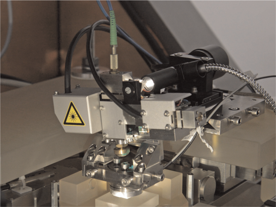
Metrological AFM head on the nanomeasuring machine (NMM-1).
Properties of the metrological AFM
The special feature of the developed metrological AFM head for the NMM-1 is the deflection detection system that comprises an interferometer and a beam deflection system, illustrated as block I in Figure 2. Due to this system, it is possible to simultaneously measure the displacement, bending and torsion of the cantilever. The interferometer measures with a resolution of 0.1 nm the vertical position of the tip directly on the topside of the cantilever. The signal of the quadrant photodiode is used for the control of the bending of the cantilever by a vertical motion of the sample while the sample is scanned with a lateral motion. Because of the permanent contact between the tip and measuring object, this mode of operation is called contact mode (CM). The measurement of the three signals (displacement, bending and torsion of the cantilever) also allows for determination of the force vector on the tip of the cantilever. The two tilt angles, the position, the spring constant and the dimensions of the cantilever can be used to calculate the orthogonal force vector components. 1
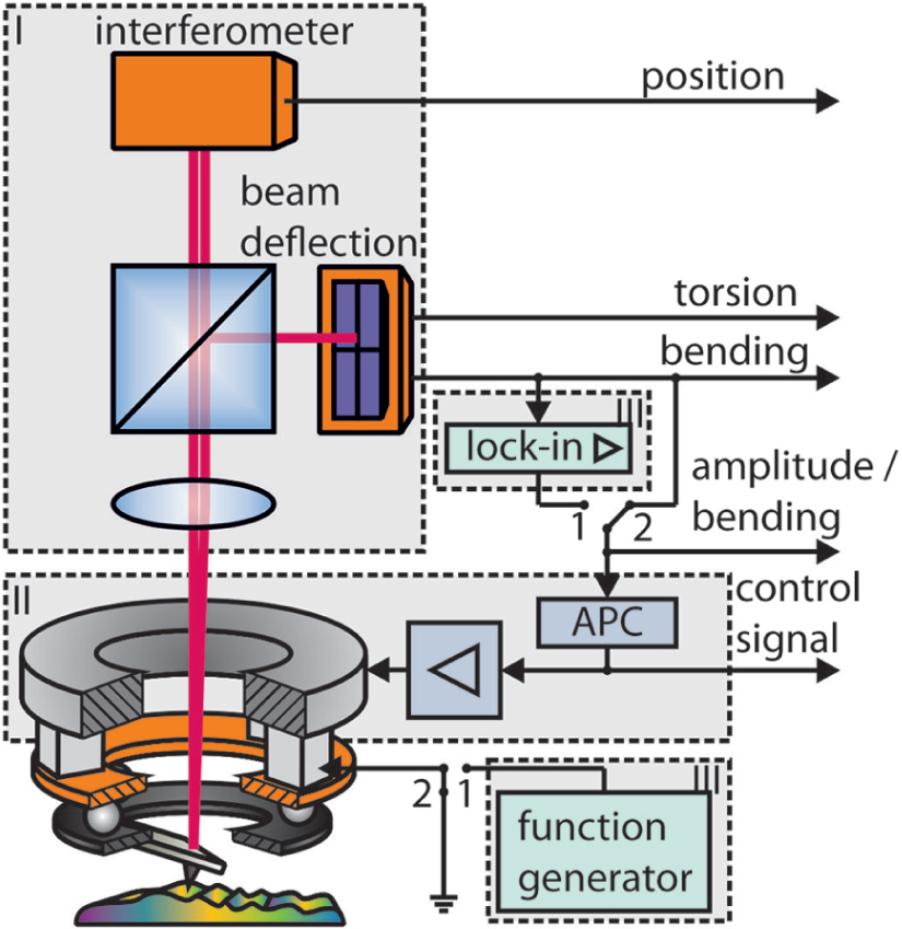
Schematic principle of the metrological AFM head (I: deflection detection system; II: piezoelectric actuator and active probe controller (APC); III: instrumentation for intermittent contact mode (IM) of operation). Mode of operation: switch position 1 – intermittent contact mode (IM) and switch position 2 – contact mode (CM).
In dynamic modes of operation, like the intermittent contact mode (IM), the cantilever is externally oscillated near its resonance frequency. The oscillation amplitude is detected and analysed by a lock-in amplifier. Both the lock-in amplifier and the function generator (block III in Figure 2) are included in the same unit. The output signal of the lock-in amplifier is used for the control of the oscillation amplitude of the cantilever and thus the distance between measuring object and tip by a vertical motion of the sample. Control dynamics and scanning speed are limited because of the high masses of the stage and corner mirror of the NMM-1. An additional high-speed piezoelectric actuator for the vertical motion of the cantilever was integrated in the metrological AFM head in order to increase the measuring dynamics (block II in Figure 2). The movement of the piezoelectric actuator is driven by the active probe controller (APC) for controlling the bending or oscillation amplitude of the cantilever. The interferometer system can be used now for precise measurement of the overall vertical cantilever motion. Hence, non-linearity and hysteresis in the actuator do not affect the measurement. The outcome of this additional control system is a much higher scan speed. 12 The notch–proportional–integral (PI) controller with two notch filters 13 is implemented currently into the APC. The parameters of this controller are the same for different modes of operations, scanning speeds and structure heights. This controller design is suitable for high-speed scans of up to 200 µm/s. 12
Calibration
For performing measurements, the sensitivity of the signals of the metrological AFM head (bending or oscillation amplitude, position and control signal) must be determined. This calibration is done by the NMM-1. The results of the calibration are the characteristic curves and regression coefficients of all AFM signals. 14,15 The electronic system of the NMM-1 uses the coefficients of a characteristic curve of the probe to calculate the distance between the cantilever tip and the sample.
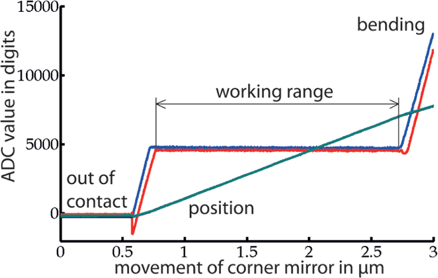
The calibration must be accomplished in two steps: The first step is the calibration of the bending (CM) or oscillation amplitude (IM) signal of the deflection detection system with the piezoelectric actuator locked. During this step, the AFM acts as a passive probe system. The characteristic curves of bending and position and oscillation amplitude sampled by the analogue digital converter (ADC) are shown in Figures 3 and 4. The working range and set point (needed for realising the constant force measurement mode) are determined from these curves.
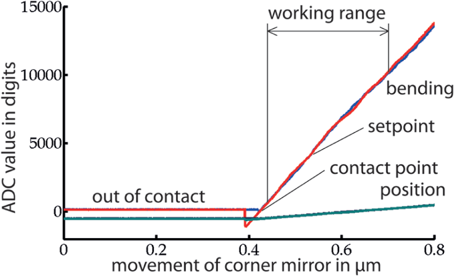
Passive probe system: characteristic curve of bending and position.
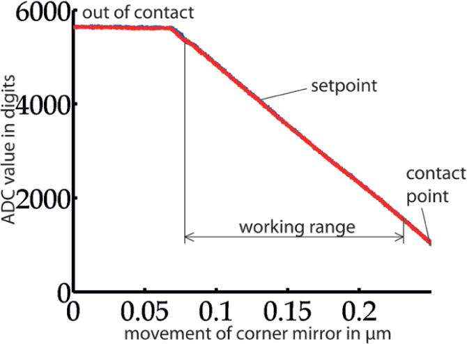
Passive probe system: characteristic curve of oscillation amplitude.
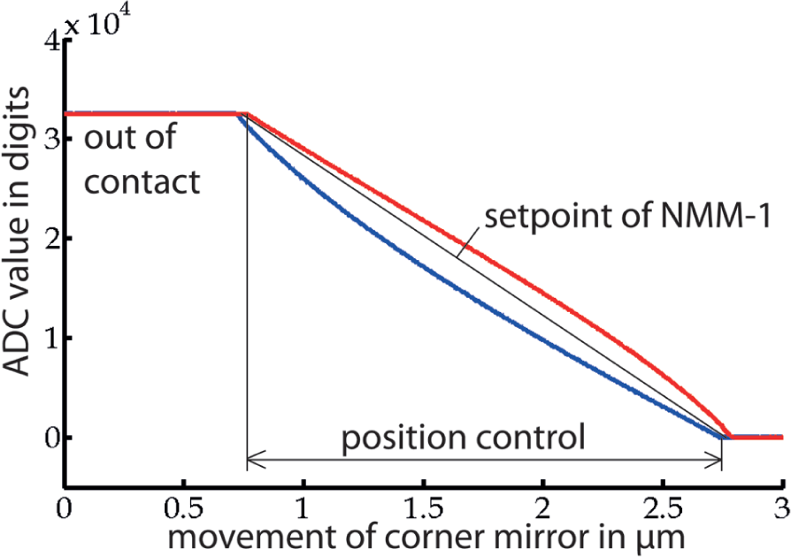
The second step is the calibration of the position (interferometer) signal with position controlled (notch-PI) piezoelectric actuator (see Figures 5 and 6). Now the scanning probe microscope (SPM) acts as an active probe system. The sample is moved up and down, and the position of the cantilever is tracked simultaneously by the piezoelectric drive within its working range, such that the bending (CM) or respectively the oscillation amplitude (IM) of the cantilever stays constant and equivalent to the set point. The bending signals for the approach (blue) and retract (red) motions are different because of the hysteresis and creep of the piezoelectric drive. As is obvious in Figure 6, the hysteresis and creep of the piezoelectric drive do not have any influence on the measurement results from the interferometer position signal (Figure 5). The two slope changes of the position signal at the working range limits of the piezoelectric drive results from the leverage of the cantilever. The focussed spot of the measuring beam is not located directly above the tip. Therefore, the deflection of the tip leads according to the lever lengths to a different length measured by the interferometer. During the actual measurement, the system remains in the working area of the piezoelectric drive. Therefore, the calibration coefficients of the position signal must be determined only for the working range.
Active probe system: characteristic curve of bending and position.
Active probe system: characteristic curve of control signal.
The repeatability of the calibration of the metrological AFM head was investigated by repeating the calibration procedure for 200 times for each mode of operation and probe system. Then, for each characteristic curve, the regression coefficients and eventually the working points were determined. The repeatabilities represented by the standard deviation of selected working points are listed in Table 1. The repeatability of a single measurement point from each signal is better than 0.3 nm.
Repeatability (standard deviation) of selected working points (set points) of the characteristic curves over 200 measurements.
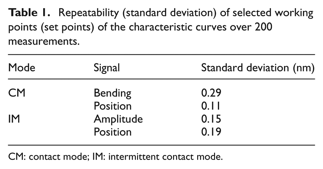
CM: contact mode; IM: intermittent contact mode.
Application for long-range measurements
Accurate measurements of lateral standards are very important in nanotechnology. These standards are used for lateral calibration of AFMs in the production lines and for the image characterisation of microscopes. The long scanning range is important for measurements over a large number of grating lines and, therefore, for better statistical results for the mean pitch. Commercial AFMs have a limited scanning range of less than 200 µm. The limited number of grid lines leads to larger uncertainties for the mean pitch value. In addition, the interferometric measurement system of the NMM-1 allows a more accurate and traceable determination of the lateral displacement during the scans. 1,16 The Physikalisch-Technische Bundesanstalt (PTB) took part in the intercomparison ‘NANO5 – 2D Grating’ with a NMM-1 and a home-built AFM head and achieved excellent results. 8
Accurate measurements require that the scan direction is perpendicular to the grating lines. 1,10,17 The sample does not need to be aligned precisely on the NMM-1 because of the large measuring range of 25 mm × 25 mm and the freely selectable lateral scan direction. The selection of the scan area and direction can be done based on the results from single line scans before the actual measurement. The one-dimensional (1D) calibration grating set TGS series (TGZ1 and TGZ2 with the structure period of 3 ± 0.05 µm) 18 was measured forwards and backwards in CM and IM. Lines of 600 µm length in CM and 1000 µm in IM with the measuring point spacing of 25 nm were scanned. The measurements were repeated 50 times in CM and 21 times in IM. The scanned-in IM profile on the TGZ2 and its magnification are shown in Figures 7 and 8. The structure period was processed using the Fourier transform method. 17,19 The mean structure periods obtained over all the measurements are presented in Table 2 for the two modes of operation (CM and IM). A better statistical result can be achieved for scans of very long lines. In this example, the standard deviation for measurements in IM is less than 0.05 nm. The deviation between CM and IM was less than 0.3 nm. The largest influences on the determined results are from the scan direction (cosine error) and the measurement range.
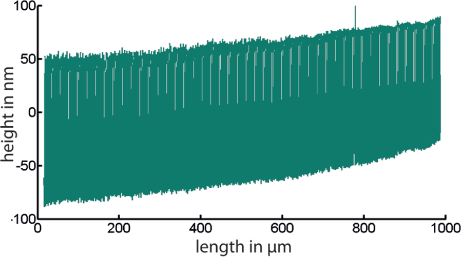
TGZ2 grating profile.
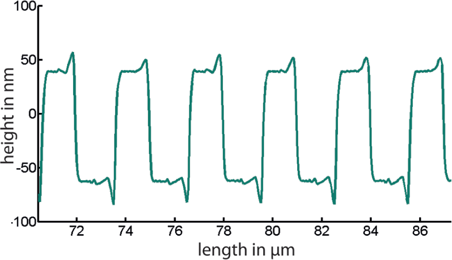
Magnification of a part of the TGZ2 grating profile (shown in Figure 7).
Comparison of the measurements results on pitch standards.
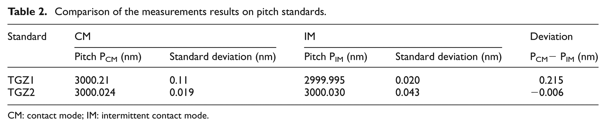
CM: contact mode; IM: intermittent contact mode.
Conclusion
This article demonstrated the application of a metrological scanning microscope head as a probe system to use in the nanomeasuring machine NMM-1 for dimensional metrology in the macroscopic range with sub-nanometre resolution. In particular, this system is able to take full advantage of the large measuring range (25 mm × 25 mm × 5 mm), high precision and traceability of the machine for effective surface measurements on 1D gratings for determination of the mean pitch. Excellent results were achieved for measurements of pitch standards. The repeatability was determined to be less than 0.11 nm for the measurements on the 1D gratings in CM and IM. The mean pitch deviation between CM and IM was less than 0.3 nm.
Footnotes
Acknowledgements
The authors wish to thank all those colleagues at the Ilmenau University of Technology who have contributed to this research.
Funding
The development of the nanopositioning and nanomeasuring machine is supported by the German Research Foundation (DFG) and the Thuringian Ministry of Education. Their support is provided within the context of Collaborative Research Centre (SFB) 622 ‘Nanopositionier- und Nanomessmaschinen’.