
Abstract
This article investigates the role that particle size and morphology have in determining the final characteristics of a part produced by direct laser deposition. 316L stainless steel in the form of traditional gas-atomised powder and metal shavings in two size ranges were deposited into multiple-layer thin-walled parts at different process parameters. The walls were characterised, considering properties such as geometry, microstructure, composition, physical and corrosive properties and results matched to the type of build material. Results showed that using particles of >150 µm, equivalent spherical diameter offered few functional advantages, leading to a process with lower deposition efficiency and part with lower mechanical properties. Using machined shavings increases deposition efficiency and can reduce gas porosity compared with powder in the same size range, but also results in higher surface oxidation, thought to be due to higher oxidation on the original shavings. This is a barrier for some applications, but the deposition of machined shavings offers significant economic advantages.
Introduction
Direct laser deposition (DLD) is one of the family of ‘additive manufacturing’ (AM) processes that can produce parts directly from computer-aided design (CAD) data by adding material in layers. 1 These processes are becoming increasingly popular in modern manufacturing: the compound annual growth rate of revenues generated by all AM products and services was 24.1% in 2009. 2 In DLD, a laser is used to create a melt pool on the surface of a metallic substrate, and metal powder of the same or different types is injected into it to enlarge the pool and subsequently fuse to the substrate. Quick scanning of the heat source produces raised tracks of rapidly melted and resolidified metal. Layers can then be built up track-by-track, and parts built up layer-by-layer to produce a fully functional part suitable for final use.3,4 The final part typically has a fine microstructure and good mechanical properties as a consequence of the fast cooling rates during deposition. However, disadvantages of the process include a slow build rate, the possibility of porosity within the tracks, an inconsistent microstructure, a rougher surface finish than required for a mating surface and the high cost of the build powder.
As one route to tackle these problems, researchers have investigated a variety of forms of build material. Powders of a single metallic material in spherical, gas-atomised (GA) form and particle sizes below 150 µm have been used in most studies.5–7 However, Arcella and Froes, 8 Froes and Eylon 9 and Froes and Suryanarayana 10 showed that use of a range of size and morphologies of particle is feasible using blended elemental, gas-atomised, plasma-rotating electrode processed and hydride–dehydride prealloyed titanium powder in the range of 44–420 µm.
Considering the effect of particle size, in an earlier study, Steen 11 noted that reduction in particle size (from 77 to 58 µm) increased the deposition rate of single tracks. Gremaud et al. 12 reported no differences in either the width or surface quality of walls deposited with different Stellite particle size distributions in the range 30–60 µm. In contrast, Smugeresky et al. 13 concluded that using smaller 316L steel powder gives a higher hardness, and that surface finish is also a function of particle size. According to Sun et al., 14 the tendency for inter-track porosity formation is higher in laser cladding with finer powder due to its smaller total area. All these studies were conducted with powder of <150 µm.
Considering the effect of particle type, Ahsan et al. 15 compared the characteristics of thin walls produced with GA and plasma-rotating electrode powder (PREP) and noted lower levels of porosity when using the PREP. The characteristics of walls built with approximately equal sizes of GA and water-atomised (WA) 316L stainless steel powder were compared, and a similar study performed with H13 tool steel.16–18 It was concluded that use of WA particles is viable but deposition characteristics are different. WA powder is cheaper than GA; however, it is still a specialised, manufactured product. Previous study also investigated cladding single layers of Inconel 617 swarf to create a protective layer on mild steel, but no comparative study between shavings and manufactured powder has been performed. 19 German has cited lack of control over the particle characteristics, chemical contamination, and irregular and coarse particle as barriers to the use of shavings as an alternative to manufactured powder generally. 20
This article compares the final properties of thin walls produced from two size categories of machining shavings and manufactured GA powder of 316L stainless steel on a substrate of the same material. Two laser power and four mass flow rate values were used in each case. The structures were analysed for dimensions, deposition efficiency, chemical composition, microstructure, hardness and corrosion resistance to allow the effects of using the different particle sizes and types to be fully evaluated.
Experimental procedure
Build material preparation
Shavings of 316L stainless steel were generated by dry milling a solid block under ambient conditions using a HURCO HAWK 30 CNC milling machine. No coolant fluid was used so as not to contaminate the shavings. The shavings were collected immediately below the cutting area and then passed through sieves of different mesh sizes to produce batches with particle sizes of<150 µm (denoted as small shavings (SS)) and 150–250 µm (denoted as large shavings (LS)). This preparation process was designed to remove two of the barriers to use shavings cited by German, namely chemical contamination and coarse particles (>250 µm).
GA powder of the same material was supplied by LPW Technology Ltd. The powder was categorised using the same method to produce batches with the same particle sizes of<150 µm (denoted as small powder (SP)) and 150–250 µm (denoted as large powder (LP)).
The four batches of particles were analysed in the same way. A Malvern Mastersizer 2000 laser diffraction system was used to determine the size distribution, and a Hitachi S-3400 scanning electron microscopy (SEM) was used to identify the morphology of particles within each batch. Ten particles from each batch were also selected at random for surface element analysis by energy-dispersive spectroscopy (EDS), which was performed using a Zeiss EVO60 SEM.
Laser deposition
A Laserline LDL160-1500 diode laser deposition system was used to prepare test samples. The system is shown schematically in Figure 1.
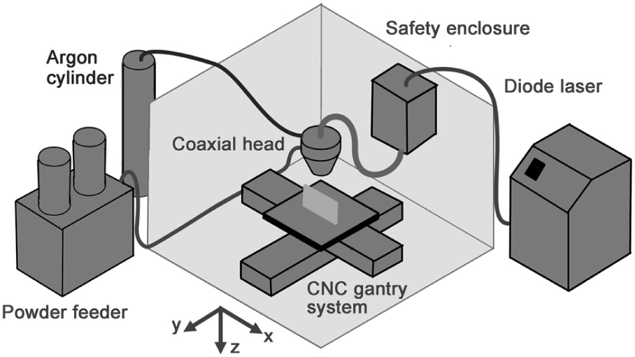
Schematic diagram of the deposition system used for the experiment.
The laser beam had a uniform, ‘top-hat’ intensity distribution and was focused to a spot of 1.7 mm diameter at the substrate surface. The particles were conveyed from a SIMATIC OP3 disc powder feeder using a 5 L/min flow of argon. The feeder was tested and calibrated prior to the experiment by measuring the mass delivery rate at different disc rotation speeds, 40 times for each of the different batches of particle. It was found that the feeder provided a consistent mass flow rate that varied linearly with disc speed in all cases. However, the metal slivers had lower tap density than the GA power and thus slightly lower mass flow rate/disc rotation speed ratio. This was accounted for when setting disc speeds during the experiment. Final delivery of particles to the melt pool was through an annular nozzle coaxial with the laser beam. The standoff distance between nozzle and substrate was maintained constant at 7.5 mm, and an additional 3 L/min flow of argon through the centre of the nozzle acted to protect the optics and provide additional shielding from oxidation.
Each sample was a thin wall consisting of five vertically aligned tracks. Each track was deposited with the substrate moving in the same direction at 4 mm/s, and each track was allowed to cool for 30 s before the next was deposited. The walls were built on 316L stainless steel substrates of 50 mm × 50 mm × 10 mm that had been grit blasted and degreased prior to use.
The experimental parameters used are shown in Table 1. A full-factorial experimental design was used with four different batches of powder, four different mass feed rates and two different levels of power, giving a total of 32 samples for analysis. The values of laser power were chosen as those known from previous experience with GA powder to give continuous, good quality tracks. Fibre losses in this system have been previously measured as 30% 21 so for this experiment the laser powers of 800 and 1000 W correspond to power densities of 247 and 308 W/mm2 and specific energies of 82.4 and 103 J/mm2 at the workpiece surface.
Experimental parameters.
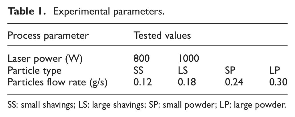
SS: small shavings; LS: large shavings; SP: small powder; LP: large powder.
Build analysis
Following laser deposition, samples were characterised for size, elemental composition, microstructure, hardness and corrosion resistance. Each sample was sliced in a perpendicular plane to the direction of laser travel (the yz plane in Figure 1) and approximately half way along the length of the track. The exposed faces were mounted in phenolic resin, ground and polished following standard metallographic procedure. The overall dimensions of the layer were measured with a Keyence VHX-500F optical microscope at 10–20× magnification and elemental distribution on the face measured using a Philips XL30 FEG SEM fitted with a Rontec (now Bruker) EDS analytical system with silicon drift diode detector. The samples were then etched electrochemically using 10% oxalic acid, and images were taken using the same optical microscope. Secondary dendrite arm spacings (SDAS) were also measured at the mid position of the wall (on the centreline at half wall height) from images taken using Hitachi S-3400 SEM equipment. The microhardness (HV) of the walls at different layer heights were measured on the wall centreline using a Buehler Instruments Micromet 5114 microindentation hardness tester by applying a load of 300 g for 8 s. Phase analysis was carried out using Philips X’pert-1 X-ray diffraction (XRD) equipment with Co X-ray tube.
To compare corrosion resistance, all wall samples were further sectioned, spot welded with Nichrome wire and cold mounted in epoxy, thus leaving the sectioned face exposed. Potentiodynamic polarisation scans were performed in 3.5 wt% NaCl electrolyte contained in a glass three-electrode cell. A saturated calomel electrode (SCE) was used as the reference electrode, and a platinum electrode was used as the counter electrode. Polarisation scanning over the range of −0.01 to 0.01 V and back versus open circuit was performed with a scan rate of 0.333 mV/s using IVIUM Compactstate electrochemical interface and impedance analysis equipment. The linear polarisation resistance (LPR) method was used and polarisation resistance (Rp) is taken as the reciprocal of the current–potential gradient. This was then used to find the corrosion rate according to the following formula: corrosion rate = BN/ρnFRp, where B is the Stern–Geary constant, taken as 26 mV, N is the atomic mass taken as 55.847 for Fe (for stainless steel), ρ is the density (8.0 g/cm3), n is the number of electrons per atom (2 electrons) and F is Faraday’s constant (96,487 C/mol).
Results
Build material
All samples had lognormal size distributions, as shown in Figure 2. The mean equivalent spherical diameter (ESD) of the SS and SP were 86.8 and 79.3 µm, respectively. The mean ESD of the LS and LP were 199.3 and 164.9 µm, respectively. In both the cases, the shavings’ size distribution had a slightly larger standard deviation.
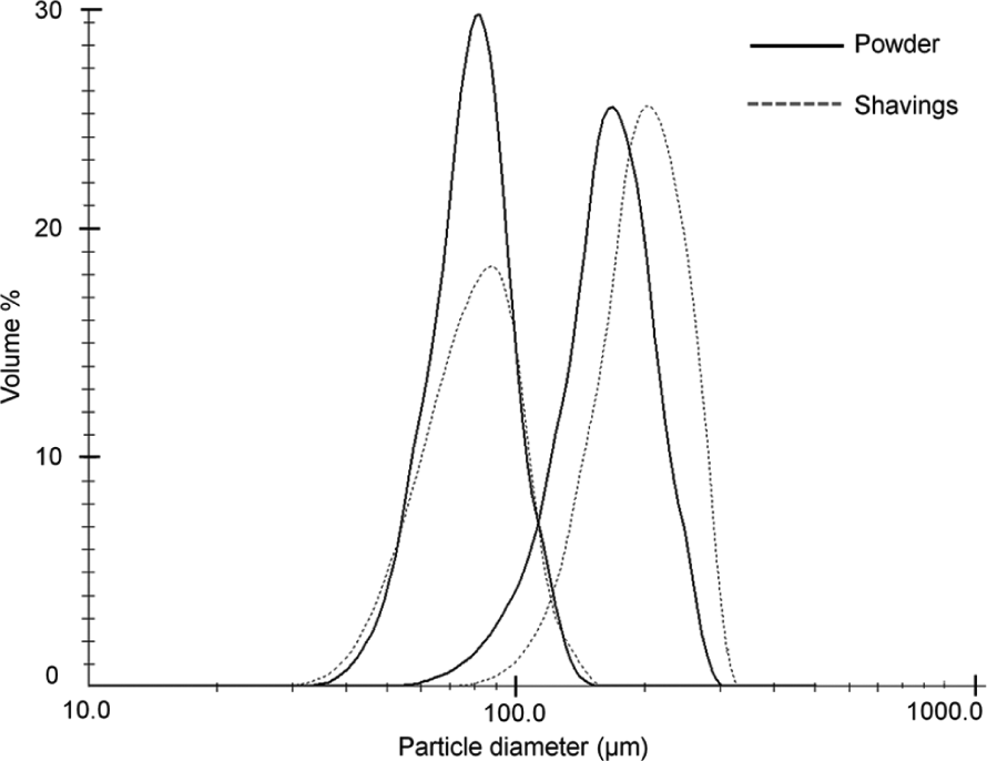
Particle size distribution of powder and shavings.
Figure 3 shows SEM images of the shavings and powder. The powder particles are mainly spherical in shape with a smooth surface, while the shavings are irregular in shape with a coarse surface texture. The shavings were further investigated by image analysis. SEM images of the shavings were taken from three orthogonal directions and particle sizes within the image collated. The mean particle size ratio in three orthogonal dimensions was found to be approximately 4:2:1 for both the SS and LS.
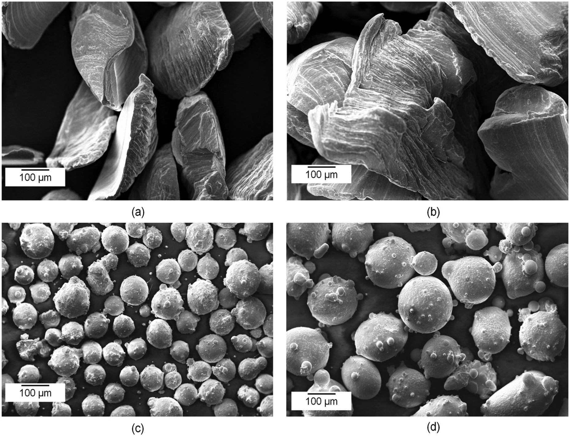
Morphology of (a) <150 µm shavings, (b) 150–250 µm shavings, (c) <150 µm powder and (d) 150–250 µm powder.
The mean quantified elemental compositions obtained through EDS point scans of powder and shavings are shown in Table 2. For both types of powder, there is higher oxygen content than in the standard metal, but this is not unexpected because stainless steel is known to spontaneously produce a thin surface layer of chromium-rich oxides in atmosphere. 22 The presence of such a layer is supported by the fact that surface levels of chromium are also higher than the literature and powder manufacturer’s levels for 316L steel. Surface levels of oxygen and carbon are higher for the shavings. The former can be attributed to the oxide layer cracking and hence oxidation increasing under the varying temperature conditions experienced by the chips during machining, and the latter to surface residues collected either during processing or testing.
Elemental composition measured through EDS.
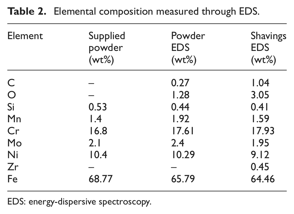
EDS: energy-dispersive spectroscopy.
Wall dimension and deposition efficiency
Figure 4 shows the variation in mean height per layer of the walls, and Figure 5 shows the variation of mean layer width with mass flow rate. In accordance with the findings of, for example, Kreutz et al., 23 mean layer height is observed to vary approximately linearly with mass flow rate at constant traverse speed. There is little difference between heights at the two levels of laser power, indicating that the process is mass-limited. Layer width increased with mass flow rate at both powers and in all cases is greater at 1000 W than at 800 W in accordance with the findings of Hu et al. 24
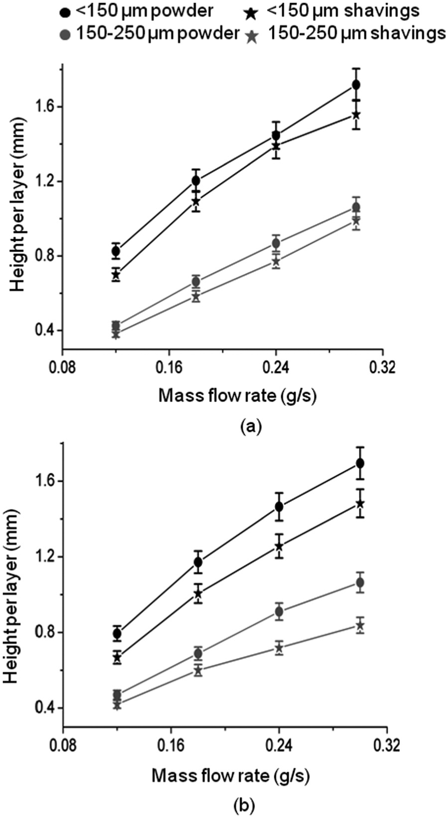
Variation of mean layer height with mass flow rate: (a) laser power = 800 W and (b) laser power = 1000 W.
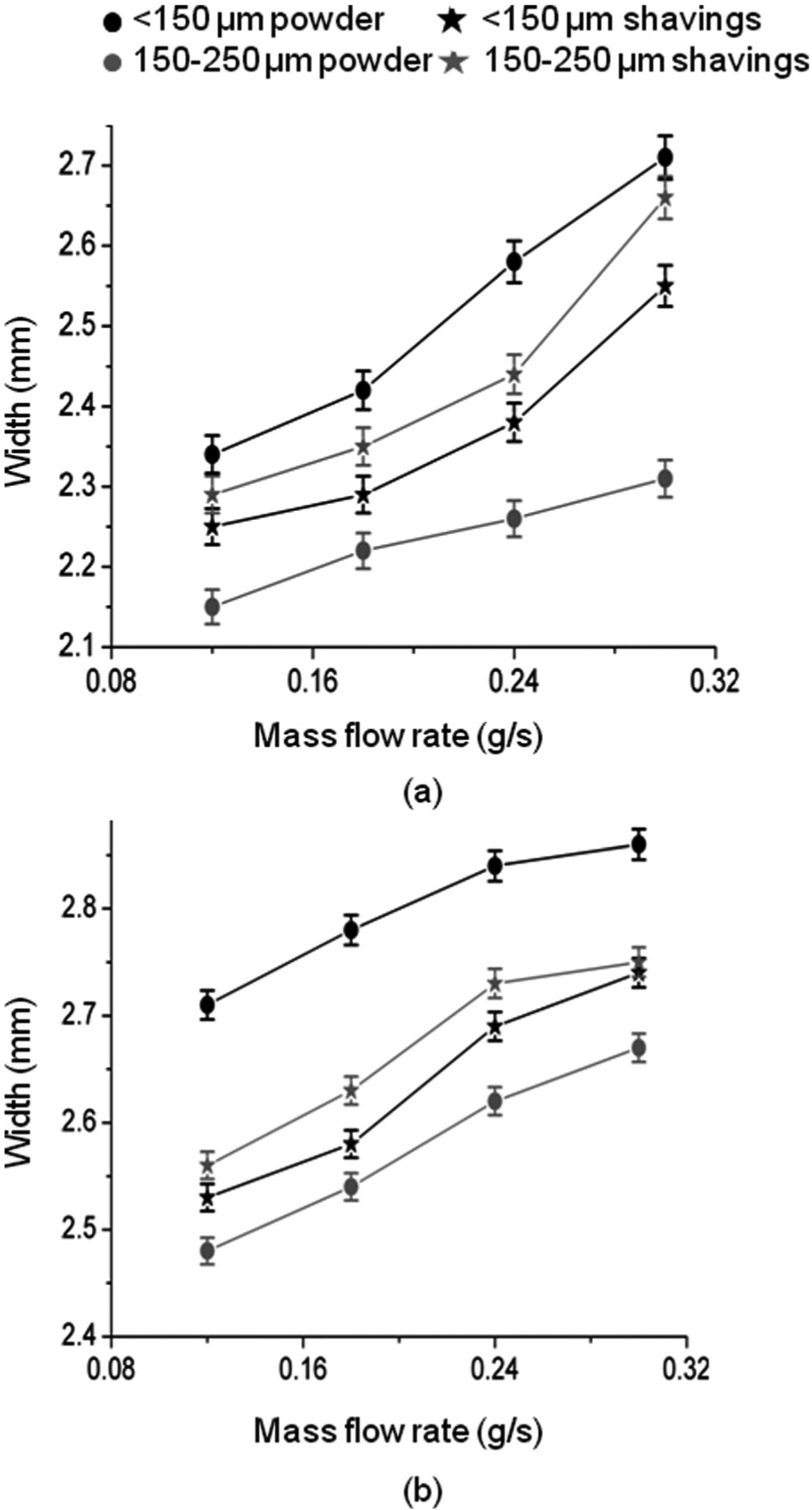
Variation of mean layer width with mass flow rate: (a) laser power = 800 W and (b) laser power = 1000 W.
The smaller particle size of both forms of material produced walls consisting of wider and significantly thicker layers at both powers. In most cases, the increase in layer width was more pronounced in walls produced at lower laser power. For this, particle size of <150 µm, using shavings rather than powder, resulted in less wide and less tall layers. Conversely, the larger particle size, using shavings rather than powder, resulted in wider although still less tall layers.
Combining the layer height and width results allowed the mean layer area of each of the walls and hence the deposition rate (density × mean layer area × scan speed) and deposition efficiency (deposition rate/mass flow rate) for the walls to be calculated. These were compiled to give a mean value for each form of material, and these are compared in Figure 6. The deposition efficiency of smaller powder (49%–57%) was found to be the best, followed by smaller shavings, then larger powder and finally larger shavings (23%–28%).
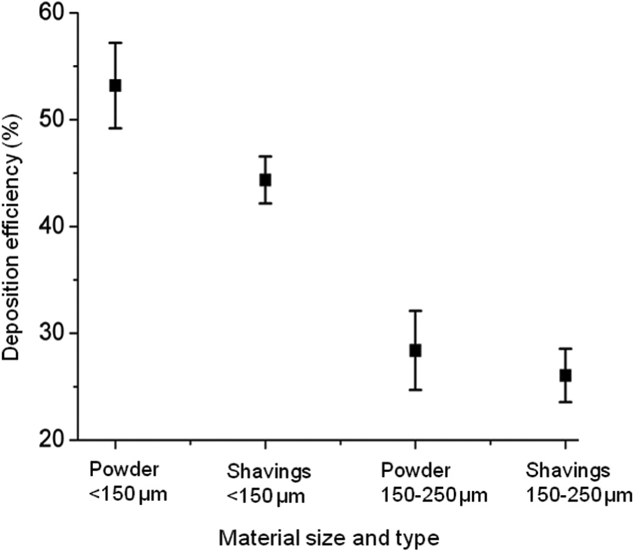
Deposition efficiency of all forms of build material.
Element and phase distribution
XRD analysis of transverse sections through the walls revealed an exclusively face-centred cubic (FCC) austenitic crystal structure with no trace of retained ferrite in any case. Figure 7 shows the XRD pattern of representative samples produced by SS and SP.
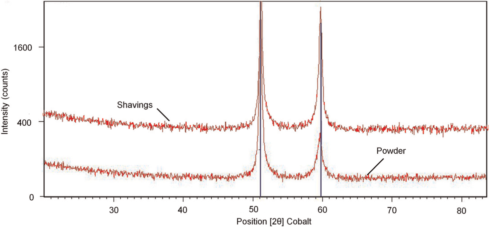
XRD pattern of samples produced by particles of <150 µm with laser power of 800 W and mass flow rate of 0.18 g/s: (a) shavings and (b) powder.
The elemental composition of walls measured in the transverse cross section closely resembled that of the original powder, with only the levels of carbon and oxygen exceeding the standard constituent levels of 316L stainless steel. These are again attributed to surface oxidation and small levels of surface contamination, possibly from the sample, polishing or mounting operations. There was no increase in the concentration of oxygen at layer boundaries; however, oxygen was found in significant concentration at the limits of the wall due to the oxidation during the DLD process.
Particle size had minimal effect on element and phase distribution within a wall; however, shavings produced walls with generally higher surface oxygen concentration. Figure 8 shows the oxygen concentration variation normal to the side of walls produced at 1000 W and 0.18 g/s. There is a thicker oxide layer (approximately 20 µm) on the surface of the wall built from shavings than on that built from manufactured powder (approximately 7 µm), which could be a direct result of the higher oxygen content on the surface of shavings than of powder (Table 2).
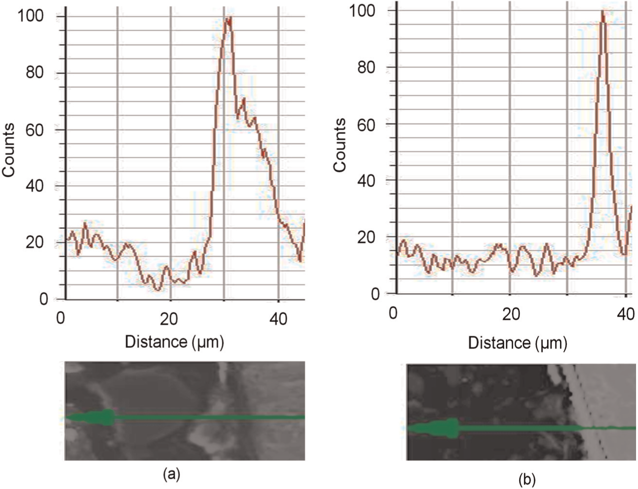
Oxygen content variation normal to the side of a wall surface produced by particles of 150–250 µm with laser power of 1000 W and mass flow rate of 0.18 g/s: (a) shavings and (b) powder.
Microstructure
Beginning from the bottom of the wall, the deposited layers had good metallurgical bonding with the substrate. Predictably, increased laser power and lower mass flow rate produced deeper penetration of the melt pool into the original substrate. At this position, the substrate acted as a large heat sink, producing high thermal gradients and a columnar dendritic structure immediately above the wall–substrate interface 25 (Figure 9).
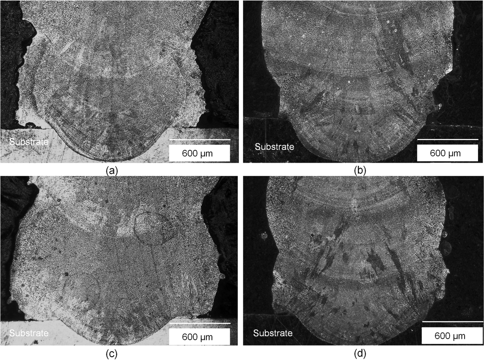
Base of walls produced at laser power of 1000 W and mass flow rate of 0.24 g/s and with (a)<150 µm shavings, (b) 150–250 µm shavings, (c)<150 µm powder and (d) 150–250 µm powder.
On moving upwards, walls underwent a transition to mainly dendritic structures due to the less favourable heat flow conditions and thus lower thermal gradients at the solidification front. 26 Figure 10 quantifies microstructural scale in terms of the SDAS measured from SEM images at half the wall height. SDAS increases with power in all cases. This is because the larger melt pool created at higher powers leads to a slower solidification rate. 27 SDAS also decreases with mass flow, which is due to the effect of this on melt pool size and also due to the increase in nucleation density in the melt pool.15,28 The SDAS in walls made by the smaller particles of<150 µm decreased with an increase in mass flow rate. When using the larger particles of 150–250 µm, there was no apparent relationship between SDAS and mass flow rate. For the smaller particles, shavings produced a microstructure with lower SDAS than powder but with the larger particles the opposite was true.
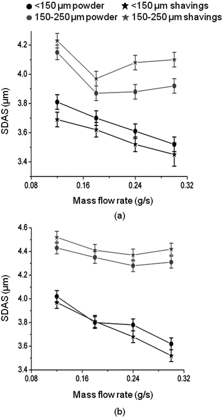
Variation of SDAS with mass flow rate: (a) laser power = 800 W and (b) laser power = 1000 W.
In the top most layers, a small region spanning to 100–150 µm was found to be occupied by columnar dendrites due to cooling by the atmosphere and a reversed solidification direction 29 (Figure 11). No interlayer porosity was visible in any of the walls, although small portions of spherical gas porosity could be seen in both walls. This was slightly more prevalent in walls built with powder than with shavings, particularly walls built with powder 100–150 µm size.
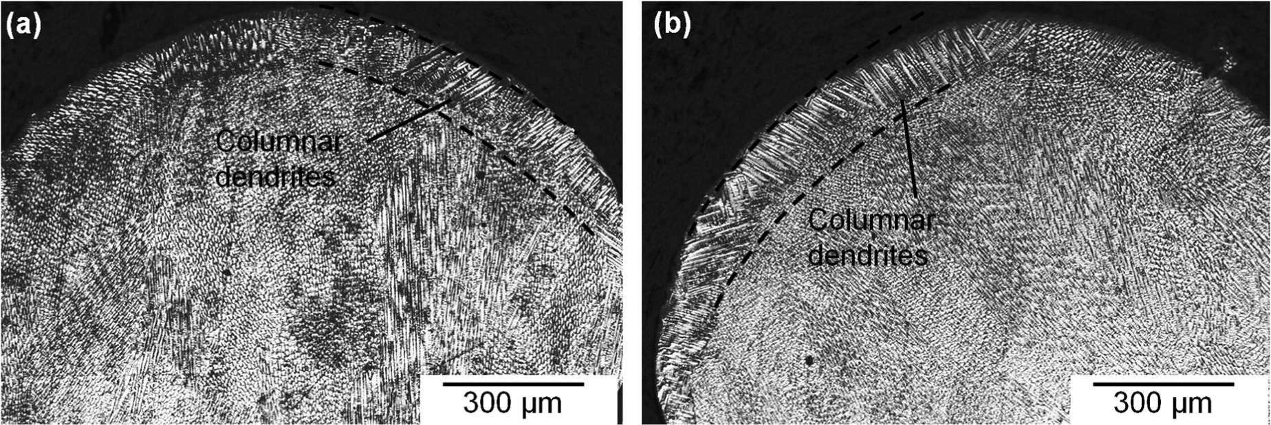
Microstructure in the upper layer of walls produced with laser power of 1000 W and mass flow rate of 0.18 g/s: (a) shavings and (b) powder.
Hardness
Figure 12 shows the variation of wall hardness with increasing mass flow rate. Hardness was found to vary within the range of 175–210 HV, and hardness was in most cases higher when using the lower power. The hardness in walls made by the smaller particles increased with an increase in mass flow rate. When using the larger particles, there was no apparent relationship between hardness and mass flow rate. For smaller particles, shavings produced harder walls than powder but with larger particles the opposite was true in most cases.
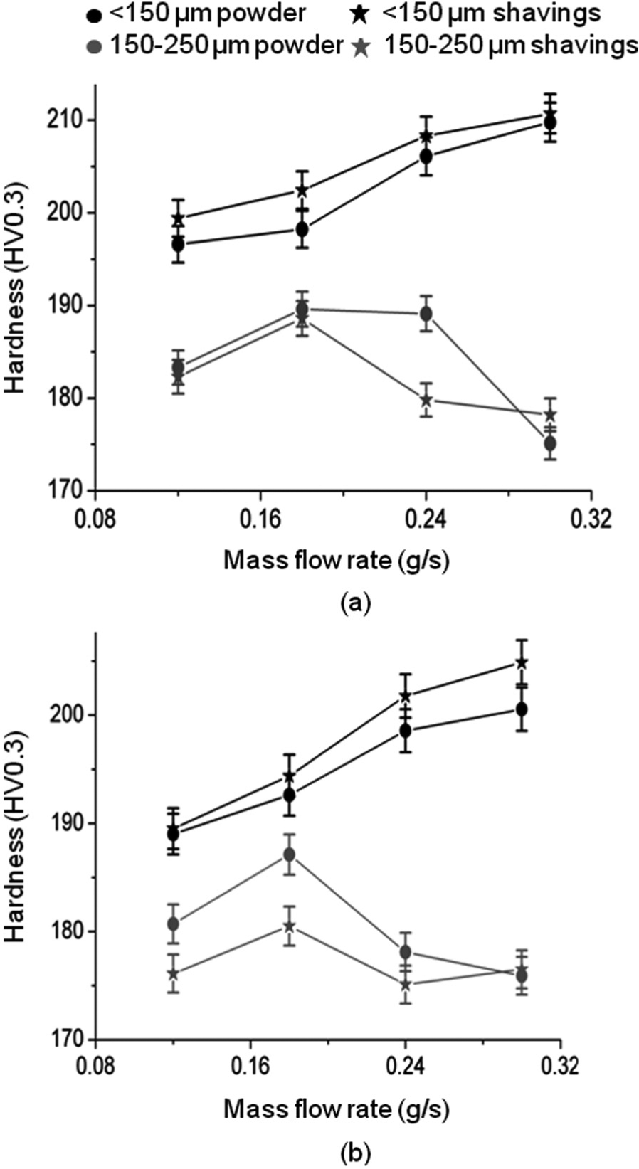
Variation of hardness with mass flow rate: (a) laser power = 800 W and (b) laser power = 1000 W.
These trends match Figure 10 well, bearing in mind the well-known Hall–Petch relationship that relates yield stress to the inverse square root of grain size.30–32 Although this expression has been shown to be an approximation, but holds good for the microstructural scale present in these walls and in the absence of phase change or precipitation effects. 33
Corrosion resistance
Figure 13 shows the corrosion rate of all samples. Walls made from powder generally displayed better corrosion resistance: there were only two exceptions to this from the 16 parameter combinations tested. There appears to be some natural variation between the samples with no clear, linear trends, but the average corrosion rates of the SS and SP were 7.93 and 4.12 µm/year, respectively, while the average corrosion rate of the LS and powder were 5.56 and 2.77 µm/year, respectively. Thus, on average, samples made using powder rather than shavings and with large rather than small particles exhibited lower corrosion rates.
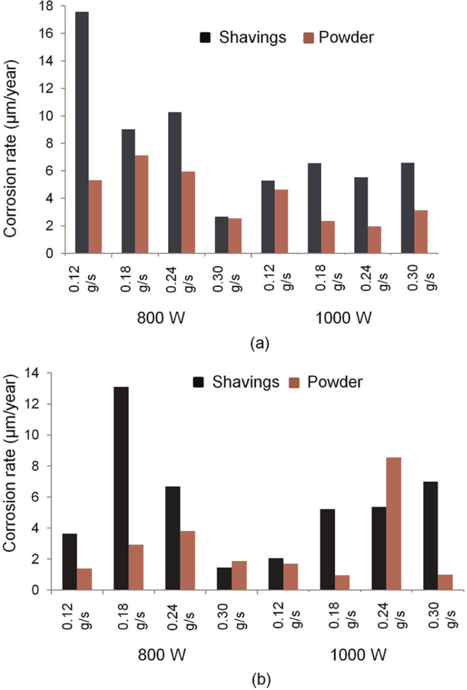
Corrosion rate using particles of (a)<150 µm and (b) 150–250 µm.
316L stainless steel is subjected to pitting or crevice corrosion in chloride solutions owing to breakdown of the passive film. 34 Therefore, to investigate this phenomenon, further additional cyclic polarisation scans over a wider range (−0.3 to +1.3 V vs open circuit) were performed on four samples, again using a scan rate of 0.333 mV/s. For small particles at 800 W and 0.30 g/s, the pitting potentials for powder and shaving walls were 0.39 and 0.23 V, respectively, and for large particles at 800 W and 0.18 g/s, the pitting potentials for powder and shaving walls were 0.19 and 0.14 V, respectively. Compared to Figure 13, this indicates that a higher corrosion rate is linked to a lower pitting potential, and samples made using powder rather than shavings can expect later onset as well as rate of corrosion.
Discussion
The thin walls produced from both types and sizes of particles were well-formed and shared many features. In most cases, the process responded in the same way when primary input variables of the process were changed: increasing layer height with powder mass flow rate; increasing melt pool, and hence track width with laser power and mass flow rate and increasing microstructural scale with laser power, and hence energy density and specific energy. It is thus initially clear from the study that it is feasible to use both sizes and both types of particles – there is no catastrophic failure of the process when radically different morphologies are used.
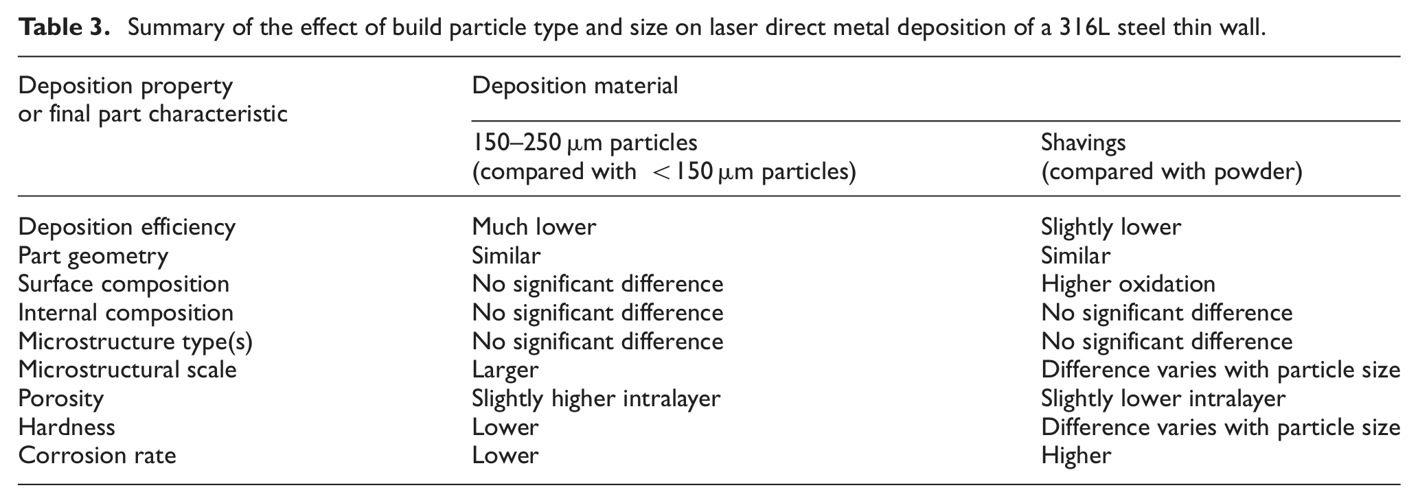
However, quantification of the walls shows that the results are not equal. Table 3 summarises the effects that particle type and size have been identified as having.
Summary of the effect of build particle type and size on laser direct metal deposition of a 316L steel thin wall.
The initial dry machining and filtering seem to have effectively prevented contamination of the shavings, although surface oxygen levels were higher in walls made with shaving than with powder, presumably due to the shavings’ thicker oxide layer produced by elevated temperatures during machining. Use of a coolant fluid during machining may be one solution, but that risks introducing further contamination. An intermediate cleaning as well as sieving step may be necessary for the surface composition of shaving walls to match those of powder walls.
The fact that there were different deposition efficiencies and microstructural scales indicates the type and size of build material affected the deposition process energy balance. Consider the interaction between the build particles and the powder stream, which is known to affect the characteristics of the built part. 16 The mean projected surface areas, A, of a GA powder particle (taken as spherical, radius r) and a sliver (taken as cuboid with sides ratio L:2L:4L and random orientation) are πr 2 and 28L2/π, respectively, and their volumes, Vp, are 4πr3/3 and 8L3. The number of particles between the laser and melt pool (Np) can be determined from the following relation

where
Assuming that there is no scattering and the particles are not close enough together to shadow each other, attenuation of the beam is proportional to the area obscured by the particles (Ao)


Taking each particle as a lumped capacity element, the rate of heating of a particle in the laser beam can be calculated by

Where
Equations (3) and (4) show that, assuming equal absorptivity, the attenuation and heating of the particles used are proportional to the ratio of projected surface area to volume (A/Vp). Table 4 compares the ratio for the particles.
Projected area:volume ratio of the different particles, normalised to that of the large powder.
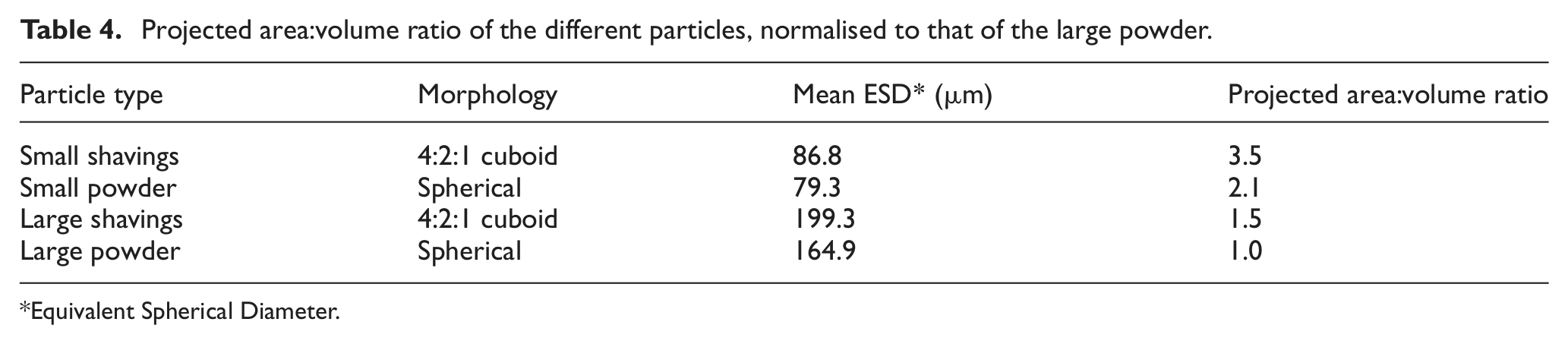
Equivalent Spherical Diameter.
According to Table 4, there was considerably less particle heating and attenuation with the larger particle sizes than those of<150 µm size. The greater laser intensity at the substrate this would have produced can be reasonably expected to have produced a larger melt pool and thus slower cooling rate, explaining the larger microstructural scale and lower hardness when using particles in the size range of 150–250 µm. However, Marsden et al. 35 summarised that deposition efficiency varies with the proportion of powder intersecting the melt pool. A larger melt pool and lower catchment efficiency implies another factor: either a different particle stream shape with the different particles or different assimilation properties. The smaller particles would have been considerably hotter so may have been assimilated by, for example, sticking to the surface outside the melt pool when the larger particles ricocheted.
Shavings were also deposited more efficiently than powder, despite attenuating the laser more than the powder above the melt pool (Table 3) and thus probably producing a smaller melt pool. As for the smaller powder, this can probably be attributed to more favourable assimilation characteristics. The strength and direction of the dominant Marangoni flow may have been an additional factor and altered the shape of the melt pool and hence area projected to the powder stream. 35 The surface tension–temperature coefficient would be altered by the greater surface oxygen level on the shavings and the temperature gradient on the surface altered by the different temperatures of the particles on reaching the surface. 16
There was no interlayer porosity, and the difference in levels of intralayer (gas) porosity can probably be attributed to pores in the GA powder. 36 In this respect, use of shavings has a clear advantage. It has been shown that even high-quality PREP preparation process cannot completely eliminate porosity in powder, and simply shaving the metal from a block completely avoids the atomisation process.
Both sizes and forms of the feed material produced corrosion-resistant walls. Shavings-made structures exhibited higher corrosion rate with a very few exceptions. This may be due to the finer surface microstructure, but this is not in agreement with the fact that smaller particles produce a finer microstructure and also less corrosion resistance. An alternative explanation is the higher carbon content initially found on the surface of the shavings (Table 2). ‘Sensitisation’ takes place when higher carbon combines with chromium and precipitates into the grain boundaries that are highly anodic and thus compromises the corrosion resistance of a material. 37 Pitting corrosion is also highly sensitive to the influences of inhomogeneity in a sample, and in particular the presence of second phase particles or inclusions.38,39 However, it is difficult to be certain of these trends because there is significant natural variation between the samples, which could be due to the irregular nature of the microstructure that is typical in this process (Figures 9 and 11) and the relatively small area of sample that was used during the corrosion tests.
The implication of these results is that there are few occasions when it would be beneficial to use particles of >150 µm. For high-volume deposition applications, for example, repair, the deposition efficiency would be a hindrance, while for high-quality applications requiring good mechanical properties, for example, the aerospace industry, the lower mechanical properties and slightly higher intralayer porosity would not make powder of >150 µm the preferred choice. One application where larger powder might be preferred would be surface cladding for corrosion protection, but as powder below 150 µm also produced reasonably corrosion-resistant layers, the possibility of greater wear due to lower hardness may outweigh the slightly lower corrosion rate of coatings produced from the larger powder.
There are no such clear reasons for excluding shavings. The results show a higher deposition efficiency and lower intralayer porosity than when using powder, both of which are desirable. A clear disadvantage is the lack of control over the cleanliness of the shavings. However, in this study, dry machining allowed contamination to be limited to higher surface oxide levels, which would be a problem in some applications, but not in all applications (e.g. when surface cladding of materials such as stainless steel for corrosion resistance).
Conclusion
Thin walls were built by laser metal deposition from four different types of 316L stainless steel build material: the de facto standard,<150 µm GA powder; larger, 150–250 µm GA powder;<150 µm machining shavings; and larger, 150–250 µm shavings. By comparing the characteristics of the final walls, it can be concluded that for the tested case:
Previously established parameter relationships for the DLD process still apply. There is no catastrophic failure or change in the nature of the process when significantly different morphologies or sizes of particle are used.
Larger particles can produce walls with similar geometries but deposition efficiency is much lower and mechanical properties are generally poorer than parts produced from smaller particles. The only measurable advantage in this experiment was a lower final corrosion rate.
Shavings enable higher deposition efficiency at the expense of higher corrosion rate; most of the advantages are similar to those of using smaller powder. The unique advantages of this form of material are the absence of internal porosity and the low cost.
The ‘contamination’ problem of using shavings has not been fully overcome, although in this study, that contamination was limited to introduction of higher surface oxidation levels on the final part.
Based on these results, the use of particles>150µm is not recommended. Shavings in the particle size of<150 µm appear as a potential alternative to powder, especially in applications where material cost is of high importance, but contamination is currently a barrier to this.
Footnotes
Acknowledgements
The authors thank to Dr Waheed Ul Haq Syed from the Department of Mechanical Engineering, College of Electrical and Mechanical Engineering, NUST, and Mr Michael Faulkner and Mr Gary Harrison from the School of Materials, The University of Manchester.
Funding
This study was financially supported by the British Council, the United Kingdom, and the Higher Education Commission (HEC), Pakistan.