
Abstract
Aluminium–SiC particulate metal matrix composites have attracted much interest in recent years among practitioners and researchers in the field of aerospace, automobile, nuclear, electronic packaging and other industries due to their low coefficient of thermal expansion, high strength and stiffness, hardness, wear and corrosion resistance properties. The present study focuses on aluminium A356 alloy with four different volume % of SiC particle–reinforced metal matrix composites synthesized by vacuum hot-pressing technique to achieve uniform dispersion of finer reinforcement over the matrix with higher densification. In order to study the machinability issues of the developed composites, computer numerical control end milling studies were conducted using central composite experimental design by varying cutting speed, feed and depth of cut, and the responses such as cutting forces and tool–work interface temperature were measured. The effect of machining parameters and reinforcement on the matrix during machining was analysed and optimized, which gives valuable guidelines to the manufacturing industries. The response surface models were developed and compared with experimental results. The results show that increase in volume % of SiCp reinforcement over the matrix results in higher tool–work interface temperature and needs higher cutting force during machining process.
Keywords
Introduction
Aluminium alloys have a good machinability index and have been enormously used in automobile and aerospace industries due to their superior properties such as higher strength to weight ratio, chemical inertness and easy heat treatable properties. However, the main weaknesses of aluminium alloys are their poor high-temperature performance and low wear resistance. To overcome these problems, aluminium alloys reinforced by ceramic particles, such as SiC, Al2O3, B4C, TiO, WC and graphite known as particulate metal matrix composites (PMMCs), have been developed. PMMCs are more attractive due to its isotropy, higher ductility and low manufacturing cost compared to others. These composites were first used in automobile industries and have recently found applications in aeronautical, aerospace, electronic and recreation industries. In PMMCs, silicon carbide particle–reinforced aluminium-based metal matrix composites (MMCs) are most commonly used due to their nearer densities to the aluminium matrix for better dispersion and can be produced in economical way. Their excellent wear resistance also makes these composites an important candidate material for the production of pistons, piston rings, brake rotors, cylinder liners, connecting rods, cams and turbocharger impellers. 1
Literature discusses many methods for the synthesis of particulate-reinforced MMCs such as powder metallurgy, melt infiltration, compo casting, melt stirring, pressurized infiltration, squeeze casting, electroplating and spray deposition of streams of molten metal and ceramic particles onto a substrate. Of these different methods, vacuum hot-pressing method has been selected in this study to make the composites with higher densification and to get better distribution of the reinforcements in the aluminium matrix especially at higher volume percentages with finer size.
Although many engineering components are produced from PMMCs to their near-net shape by casting and forming processes, they further require machining processes like turning, milling, drilling, grinding, electrical discharge machining and so on to achieve the desired shape and dimensions with specified surface finish and tolerances. But machining of PMMC is a challenge due to the existence of hard abrasive reinforcement particles in the soft matrix that causes high tool wear by abrasion, microcracks and excessive heat generation because of low thermal conductivity. Among various machining processes, end milling is most widely used in manufacturing industries in view of its capability to yield high material removal rate and to achieve reasonably good surface qualities. It is also the most common machining process after turning in metal-cutting operation and is particularly used for making slots, shoulders, contours, profiles, precision moulds, dies, thin wall machining and finishing of machined parts.
Material removal rate, surface finish, tool wear, cutting forces, tool–work interface temperature and type of chips formed are the main key factors to assess the machinability of materials. In machining, measuring of cutting force is very important because if the cutting force rises, the power consumption, tool wear, tool breakage, cutting temperature, self-excited and forced vibrations also increase, which lead to increase in machining cost. Similarly, surface roughness also influences the quality and several functional attributes of a part, such as light reflection, heat transmission, coating characteristics, surface friction, fatigue resistance and aesthetic appearance. Recently, studies have reported the use of response surface methodology (RSM) and artificial neural network (ANN) techniques on Al–SiC MMC during end milling process for the measurement and prediction of cutting force and surface roughness. Turgut et al. 2 studied the effect of cutting speed, feed, depth of cut and cutting tool types on Al–Si alloy with 5 wt% SiCp MMC made by pressureless sintering process. They concluded that the cutting force increased with the increase in feed and depth of cut and significantly decreased by increasing the cutting speed. Ganesh Babu et al. 3 developed an analytical model for cutting force components in end milling of Al–SiC composites made by stir casting technique with high-speed steel end mill cutter. They showed that the cutting force in tangential direction increases when the depth of cut increases, and also the cutting force components are more sensitive in the high speed and full immersion conditions. Abou-El-Hossein et al. 4 used RSM to predict cutting force in end milling operation of modified AISI P20 tool steel with TiN-coated carbide inserts. They used Box-Behnken–based design of experiment to conduct the experiments with input process parameter such as cutting speed, feed and axial and radial depth of cut to measure the cutting force. Close agreement was achieved between experimental and predicted results.
Suresh Kumar Reddy et al. 5 studied quality of components produced via stir casting during the end milling of Al–SiCp MMCs. Their results show that the presence of reinforcement enhances the machinability in terms of both surface roughness and lower tendency to clog on the cutting tool, when compared to a non-reinforced Al alloy. Karthikeyan et al. 6 investigated face milling characteristics of LM25 A1–SiC particulate composites produced through stir casting at different cutting speed, feed and depth of cut on different volume % of SiC particle–reinforced MMC. They found that the volume fraction of SiC particles present in the aluminium alloy matrix has a significant effect on the milling characteristics in terms of increased tool wear and specific energy simultaneously decreasing the surface roughness. Devarasiddappa et al. 7 have applied ANN and RSM model to predict the surface roughness during end milling of different wt% of SiC particle–reinforced LM25 aluminium alloy–based MMC at different machining parameters. They showed that ANN predicts better than RSM model and also surface roughness varies directly for feed rate and SiC percentages, whereas it bears inverse relationship with cutting speed.
Cutting temperature is the important factor that directly affects the tool wear, work surface integrity and machining precision especially in the high-speed machining process. Infrared radiation pyrometer with two optical fibres was used to measure the cubic boron nitride (CBN) tool–chip interface temperature in end milling of 0.55% carbon steel. 8 The tool–chip interface temperature in up milling is lower than down milling for the same machining conditions. Temperature distribution between the tool–workpiece interfaces in high-speed end milling of aluminium alloy (Al–Cu4–Mg) was experimentally measured using infrared thermometer. 9 The experimental results were verified with simulation model from finite element method based on Beck’s inverse heat conduction theory. Temperature on the flank face of cemented carbide insert during high-speed end milling process was measured in AISI 1045 material using a two-colour pyrometer with a chalcogenide optical fibre at different cutting speed, feed and radial depth of cut. 10 Results showed that the temperature on the flank face is significantly affected by cutting speed followed by radial depth of cut and feed per tooth. Park et al. 11 performed an experimental study to measure the cutting force, surface finish and tool–work interface temperature in ultrahigh-speed spindle system. They used non-contact radiation thermometer to measure the tool–work interface temperature and found the optimal combination of process parameters for improving the responses using RSM.
In metal-cutting process, tool wear directly affects the precision and cost efficiency of machining. Karakas et al. 12 studied the effect of various cutting tools in milling process of Al–4Cu–20 vol% B4Cp MMC made by liquid-phase sintering process. They have measured flank wear by varying cutting speed with constant feed and depth of cut and concluded that the flank wear of all investigated tools increased with increasing cutting speeds and triple coated (TiCN+Al2O3+TiN) cemented carbide tool exhibited the best wear resistance. Arokiadass et al. 13 investigated the end milling characteristics of LM25 Al–SiCp composite made by stir casting process. They developed RSM model to predict and optimize the flank wear of the tool and reported that spindle speed and content of SiCp were found to have greater influence on tool flank wear followed by feed rate and depth of cut. Flank wear and surface roughness were measured experimentally using Taguchi technique design in A356 alloy with 10 vol% of SiC PMMC made by stir casting. 14 They have reported that the surface roughness and tool wear decreased with increase in cutting speed and increased with increase in feed and depth of cut.
From the extensive literature survey, it is observed that the correlation between the machining parameters on cutting force, surface finish, tool wear and tool–work interface temperature have been developed from the experimental data as well as the mathematical models on Al–SiC MMCs for different machining processes. Only the effects of machining parameters such as cutting speed, feed and depth of cut on different machinability responses in MMCs synthesized by stir casting process have been extensively examined. The effects of presence of different volume fraction of SiC particles during machinability study in PMMCs synthesized especially by vacuum hot-pressing process in computer numerical control (CNC) end milling process have not been explored in depth. Therefore, the main objectives of the present work are (1) synthesis of highly isotropic particulate A356–SiCp metal matrix with higher densification by vacuum hot-pressing–assisted powder metallurgy technique, (2) end milling (up milling) machining studies on four different volume % of SiC particle–reinforced MMC by varying cutting speed, feed and depth of cut, (3) analysing the effect of individual parameter on cutting force and tool–work interface temperature and predicting these responses using multiple regression analysis models and (4) use of analysis of variance (ANOVA) to identify the significant independent and interaction factors that affect each responses and their contribution.
Experimental procedure
Synthesis of materials
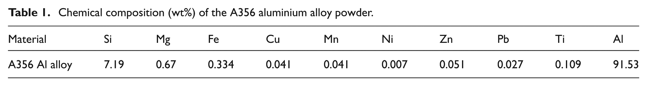
A356 alloy powders of size ranging from 25 to 50 µm and SiC particles of mean size 1 µm were used as raw materials. The chemical composition of aluminium alloy powder used is given in Table 1.
Chemical composition (wt%) of the A356 aluminium alloy powder.
The powders were weighed as per the proportions (matrix alloy with 5, 10, 15 and 20 vol% SiC particles) and blended for 6 h at 200 r/min using planetary ball mill in isopropyl alcohol medium. The mixed powders were dried in an oven for 3 h at 85 °C and then poured in a graphite die of 125 mm diameter for further hot pressing. Graphite foil of 0.5 mm thickness was pasted at the internal surfaces of the die and outer surface as well as on front face of the punch, which helps in easy dismantling of die punch system and removal of hot-pressed samples without sticking on the die wall, which is the major problem encountered during hot-pressing or squeeze casting process.
Cold and hot compaction were carried out in a vacuum hot press (VHP) that has a cylindrical hot zone of 550 mm diameter and 500 mm height and ability to process the materials with the maximum temperature of 2000 °C under 250 ton load with a maximum vacuum of 10−5 mbar. The cold compaction was carried out at a pressure of 15 MPa in room temperature. During hot pressing, material was heated slowly in order to spread the heat uniformly around the punch and die system at a rate of 4 °C/min till 150 °C and 7.5 °C/min till 600 °C, which is the final required temperature. Hot pressing has been started gradually from 550 °C onwards, and the final pressure of 20 MPa was applied at 600 °C for 30 min. The process parameters for conducting the experiments are adopted from the literature.15,16 The pressure on the punch and die assembly was not released immediately until the furnace temperature cooled down to 300 °C to avoid back expansion and improve the densification of the composites. Figure 1 shows the five different hot-pressed blanks of 125 mm diameter and 20 mm thickness.
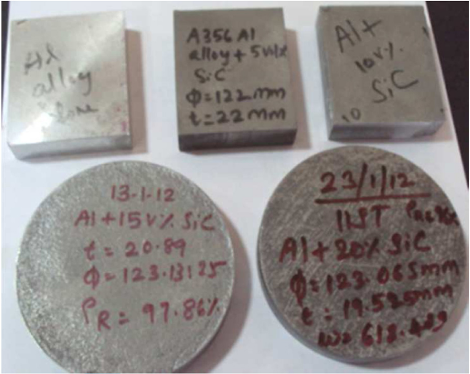
Five different hot-pressed blanks.
The combination of pressure and temperature in a vacuum atmosphere promotes bonding of particles and reduction of porosity, thus yielding composites with high relative density. Using Archimedes principle, densities were measured and the average relative densities of all the materials showed 95.58%, which confirms the higher density with minimal porosity.
Machining centre and cutting tool
Rectangular pieces of size 72 × 62 × 20 mm were cut from the processed materials in order to fix on the dynamometer. End milling studies of these composites were carried out on a three-axis CNC vertical high-speed machining centre (make and model: Jyothi Huron-K2X10, spindle speed maximum up to 28,000 r/min and power of 30 kW with a table feed of 60 m/min) under wet condition with high-pressure coolant. End mill cutter with inserts was checked to ensure a run out of less than 10 µm using a dial indicator of 1 µm resolution.
After conducting trial experiments by up and down milling process with partial immersion (shoulder milling) of the end mill cutter at 50%, 60% and 75%, lowest values of cutting force, highest values of material removal rate with best surface finish were obtained at 75% immersion of the cutter on the workpiece during up milling process, which was used in this study. Figure 2 shows the complete experimental setup.
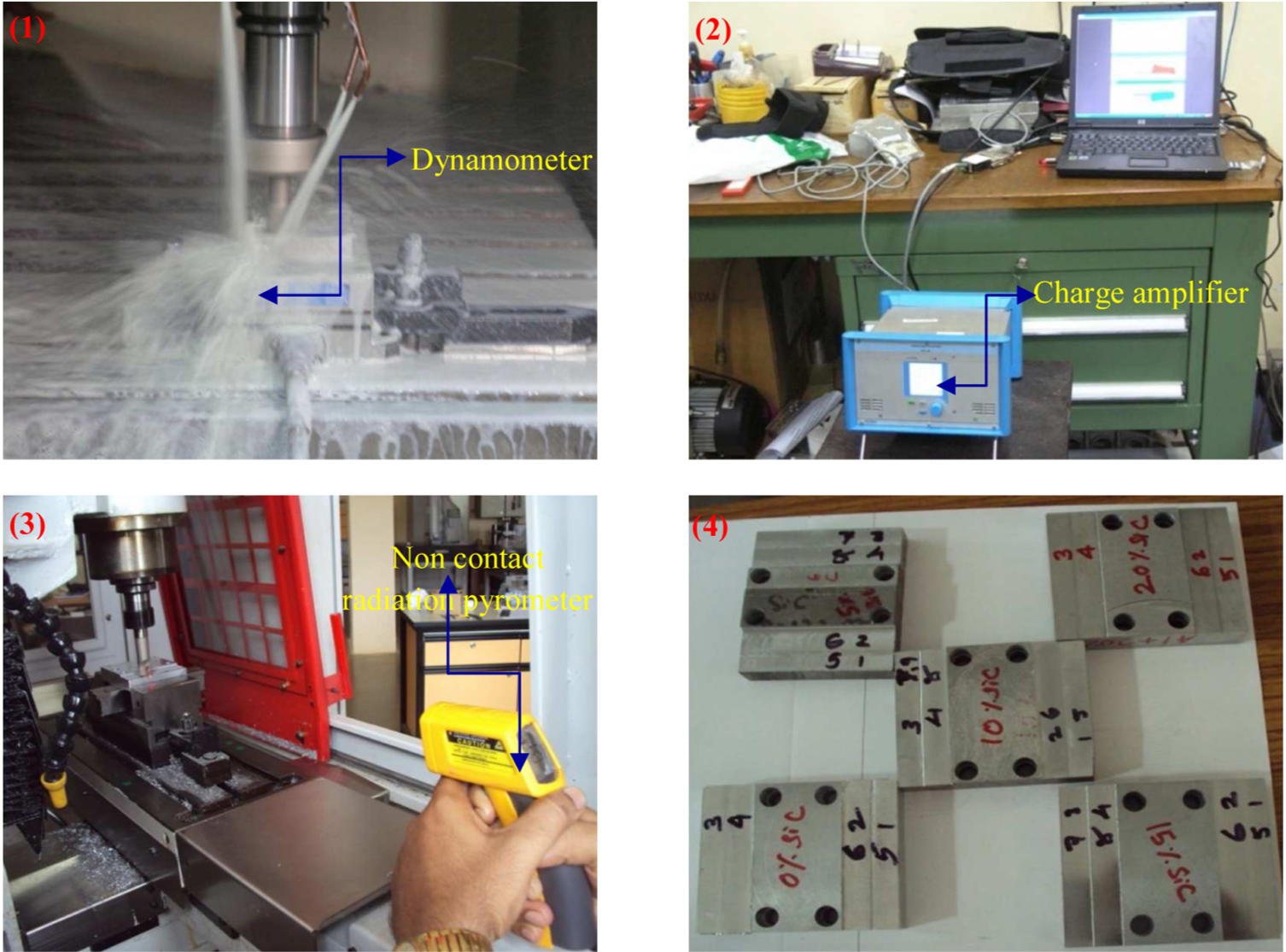
Experimental setup: (1) workpiece mounted on the dynamometer, (2) charge amplifier with DynoWare software, (3) temperature measurement using non-contact infrared thermometer and (4) machined workpiece.
End mill cutter of 16 mm diameter with two uncoated cemented carbide inserts (R 390-11 T3 04E-NL H13A) supplied by Sandvik was used in this experimentation. Inserts have a nose radius of 0.4 mm, thickness of 3.59 mm, width of cutting edge of 0.9 mm and relief angle of 21°. During the machining process, cutter with projection length of 40 mm was maintained to get higher rigidity.
Measuring instruments
Cutting force measurement
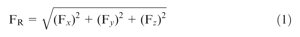
A KISTLER-made 9257B multi-component quartz dynamometer was used to measure the cutting force components. Dynamometer was mounted on the table using specifically made fixture, and the rectangular workpiece was clamped directly on the dynamometer. Multichannel charge amplifier of type 5070A and DynoWare software were used to collect the force components in the x, y and z directions. The resultant cutting force FR was calculated using the following relation
Tool–work interface temperature measurement
Non-contact infrared laser-type radiation pyrometer supplied by FLUKE, USA, with K-type thermocouple was used to measure the temperature by moving and precisely focussing the laser source at the tool–work interface, which observes the infrared energy radiated from the workpiece. It has a temperature measuring range from −30 °C to 500 °C, with an accuracy of ±1 °C and resolution of 0.1 °C. A standoff distance of 30 mm was maintained between the pyrometer and temperature-measuring spot with emissivity correction of 0.02. Coolant was switched off while measuring temperature.
Process parameters and experimental plan using design of experiments
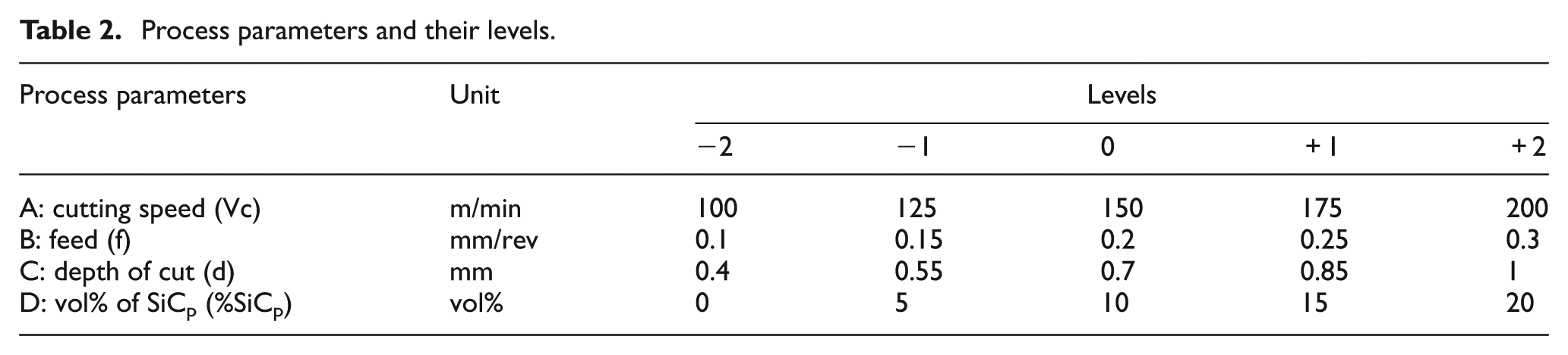
The factors contributing to the cutting force and tool–work interface temperature during end milling of MMCs are work material (vol% or wt% of ceramic particles, particle size, type of ceramic particle, base alloy chemical composition, etc.), machining parameters (up and down milling, cutting speed, feed and depth of cut), tool material, geometry and so on. Among these, cutting speed, feed, depth of cut and volume % of SiC particles were considered as the process parameters for the present work. Table 2 lists the process parameters and their levels.
Process parameters and their levels.
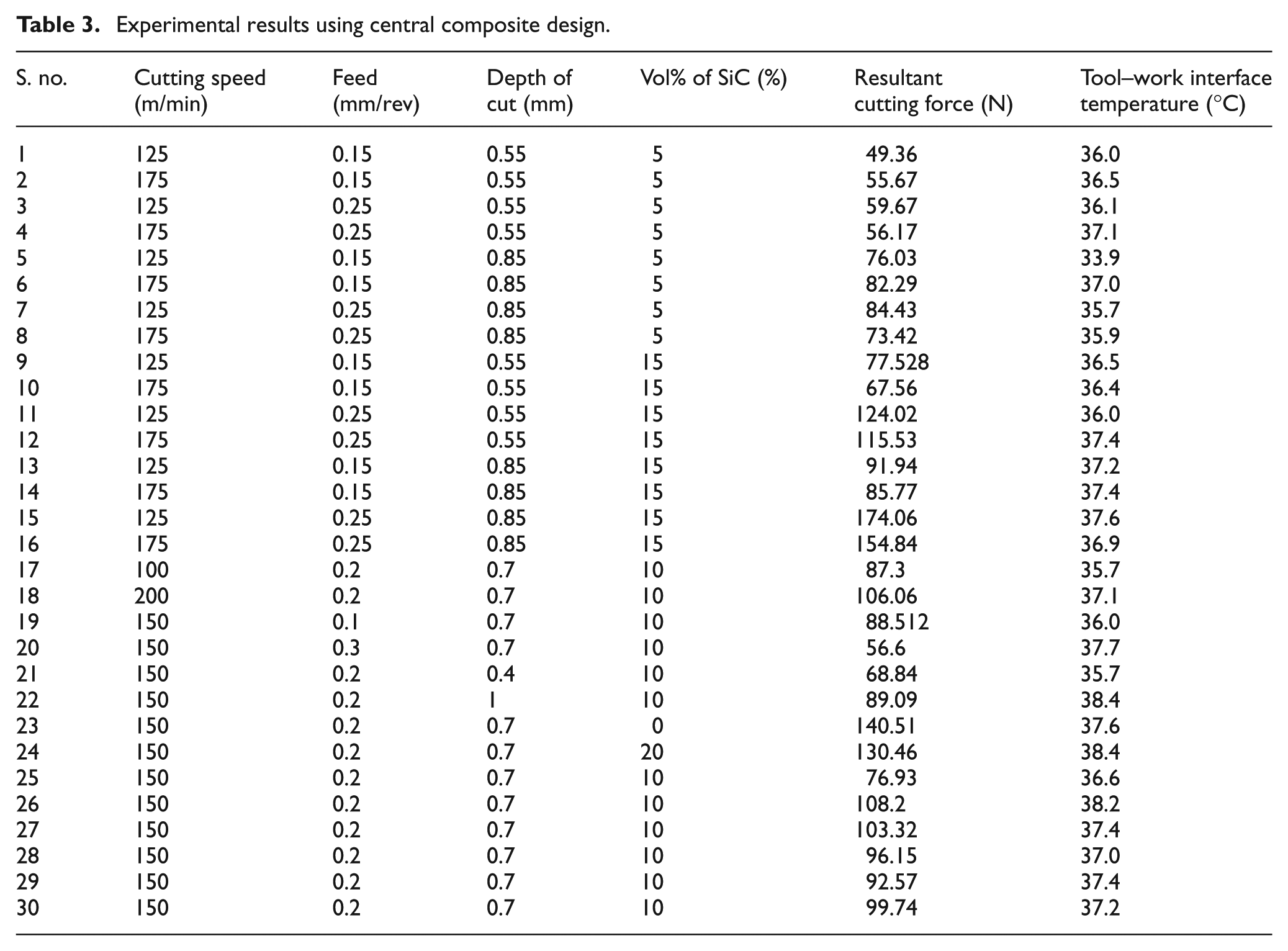
A good design can decrease the number of experiments, but the error of the model does not change intensely at the same time. Classical design styles, which are central composite design (CCD), Box–Behnken, Plackett Burman, regular simplex and full factorial, are widely used in the machining procedure design when the factors can be specified by the experimenter at the beginning of the experiment. In this article, CCD is used for designing and modelling the experiments, which is exclusively used for five-level experiments and is shown in Table 3. Thirty numbers of experiments were conducted, which consist of 16 factorial point experiments, 8 axial points at a distance of ±2 and 6 centre point experiments. Inserts were indexed and changed at the end of 10 experiments to avoid wear on the inserts, and therefore, the effect of process parameter on tool wear is not considered in this study.
Experimental results using central composite design.
Results and discussion
Microstructure
Before conducting the machining studies on the synthesized composites, microstructure analysis is carried out to verify the uniformity in distribution of SiC particles in Al matrix. Microstructure of the A356 alloy and Al–SiCp composites observed under optical microscope with 500× magnification are shown in Figure 3(a)–(e). From the microstructure images, it is observed that the distribution of SiC particles in the matrix is uniform. Furthermore, micrographs reveal strong bond between the reinforcement and the matrix. Clustering nature of SiC particles is found in composite with higher (20 vol%) content of SiC particles, which is shown in Figure 3(e).
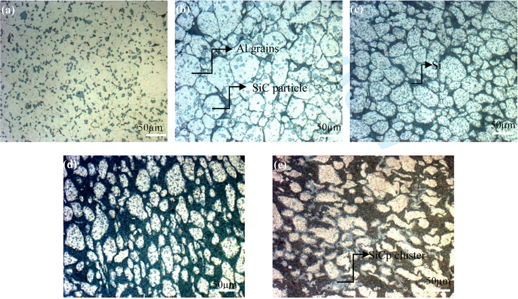
Microstructure images of (a) A356 alloy, (b) MMC with 5% SiC , (c) MMC with 10% SiC, (d) MMC with 15% SiC and (e) MMC with 20% SiC.
Modelling of cutting force
Cutting force measurement is very important in metal-cutting operation, which helps to estimate power consumption and also enables selection of the power sources during design of the machine tools and moreover used for condition monitoring of the cutting tools and machine tools. To assess the machinability of Al–SiC MMCs, cutting forces were measured in wet machining condition. Figure 4 displays the schematic view and coordinate system of the end milling process. From this figure, cutting force in feed direction indicates F x , cutting force in the direction of cutter rotation indicates F y and axial direction indicates F z .
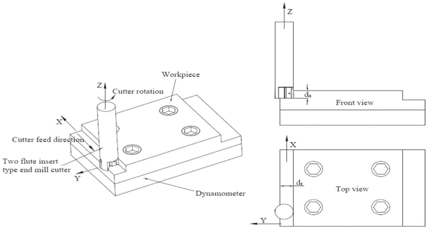
Schematic diagram of end milling process.
The cutting force signals in the x, y and z directions with respect to time in seconds obtained from the dynamometer for the 16th experimental condition is shown in Figure 5. The mean value of F x , F y and F z are 41.7, 82.34 and 124.33 N, respectively. It should be noted that the cutting force component in axial direction (F z ) is the dominant force component, which is about three times that of the force in feed force direction (F x ) and 1.5 times of force in the direction of cutter rotation (F y ).

Cutting force signals for 16th experimental condition: V (+1) = 175 m/min, f (+1) = 0.25 mm/rev, d (+1) = 0.85 mm and vol% of SiC (+1) in the composite = 15%.
From Figure 6(a), cutting force decreased with increase in cutting speed. The reason for this behaviour is due to the increase in cutting temperature in the shear zone that consequently resulted in the reduction of yield strength of the workpiece material. With reduction in the yield strength of the material, less force is sufficient for removing the materials. The increase in feed and depth of cut leads to increase in cutting force observed from Figure 6(b) and (c) due to the increase in normal pressure, chip load per tooth and size of chip cut per tooth. As seen from Figure 6(d), initially cutting force is high in aluminium alloy due to the formation of continuous chips with built-up edge (BUE) and then decreases because of delays in the formation of BUE caused by the incorporation of small amount (5%) of ceramic particles. Further increase in ceramic reinforcements strengthens and hardens the composite. The consequent increase in resistance offered by the reinforcement particles present in the matrix requires higher amount of cutting force while debonding and shearing of the materials.
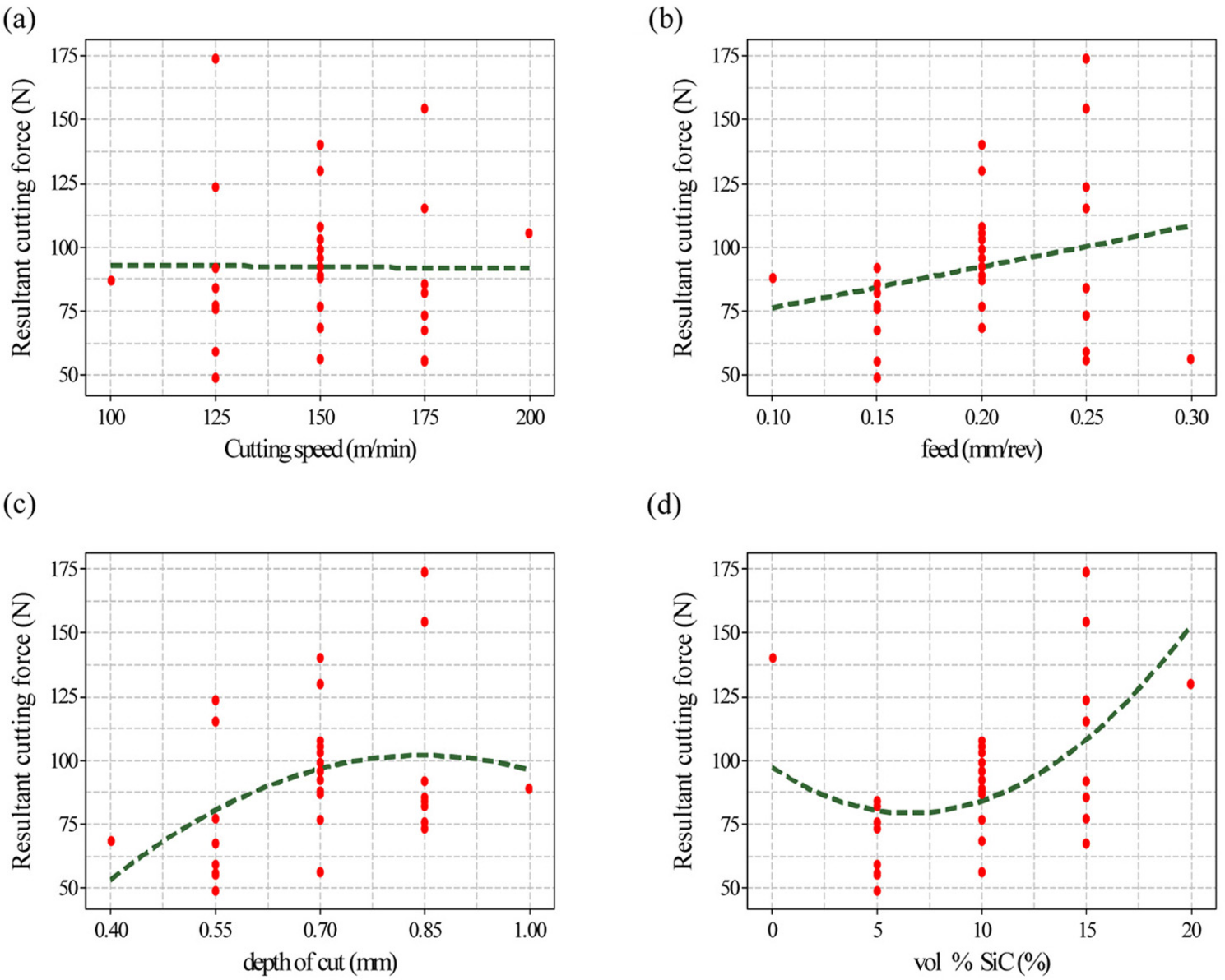
(a–d) Effect of process parameter on resultant cutting force.
RSM with CCD is a statistical design and analysis tool that combines the mathematical and statistical techniques that are useful to find the influence of process parameters on responses and to optimize the responses. Best regression equation can be fitted from the collected experimental data using RSM, which is used to describe the close relation between input and output responses. This method is also used to analyse the effect of individual factors separately and the two-factor interaction. The quadratic response surface equation for resultant cutting force was obtained using Design Expert Software 7.0.1 in terms of actual factor which is given below
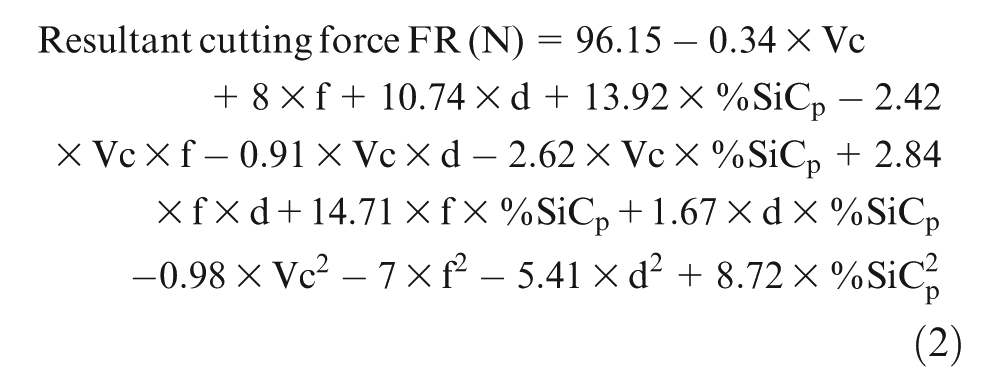
Most significant factors and their effect are identified through higher constant value corresponding to the respective factors and its magnitude in the developed mathematical model. Correlation coefficient (R2) of the predicted model for FR was found to be 0.7, and adjusted R2 was 0.4, which shows reasonable correlation between the predicted and experimental values. The low value of R2 is due to the dynamic characteristics of composites, cutting tool action and dynamics of machine.
The comparison between the predicted and experimental results is shown in Figure 7. From the graph, the developed model is in close agreement in direction and magnitude with the experimental results. The capability of the developed model (2) was tested using the ANOVA technique, and the results of quadratic response surface model fitting in the form of ANOVA are given in Table 4.
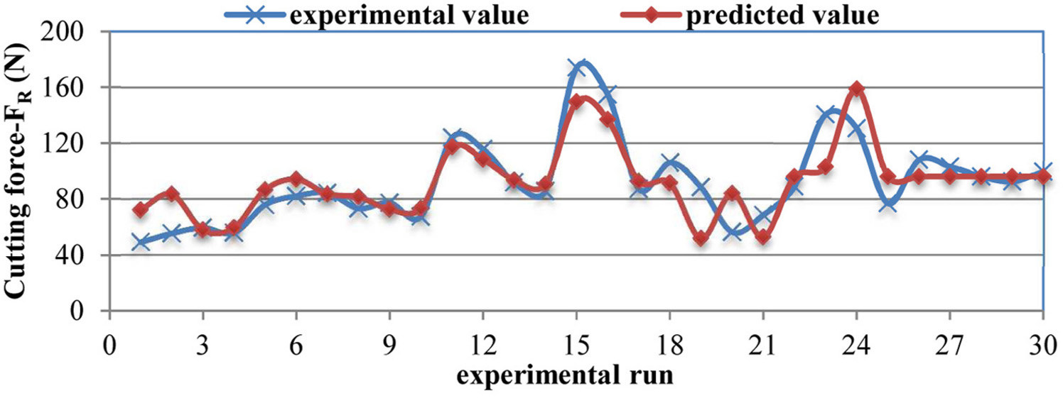
Experimental versus predicted cutting force.
ANOVA result for resultant cutting force.
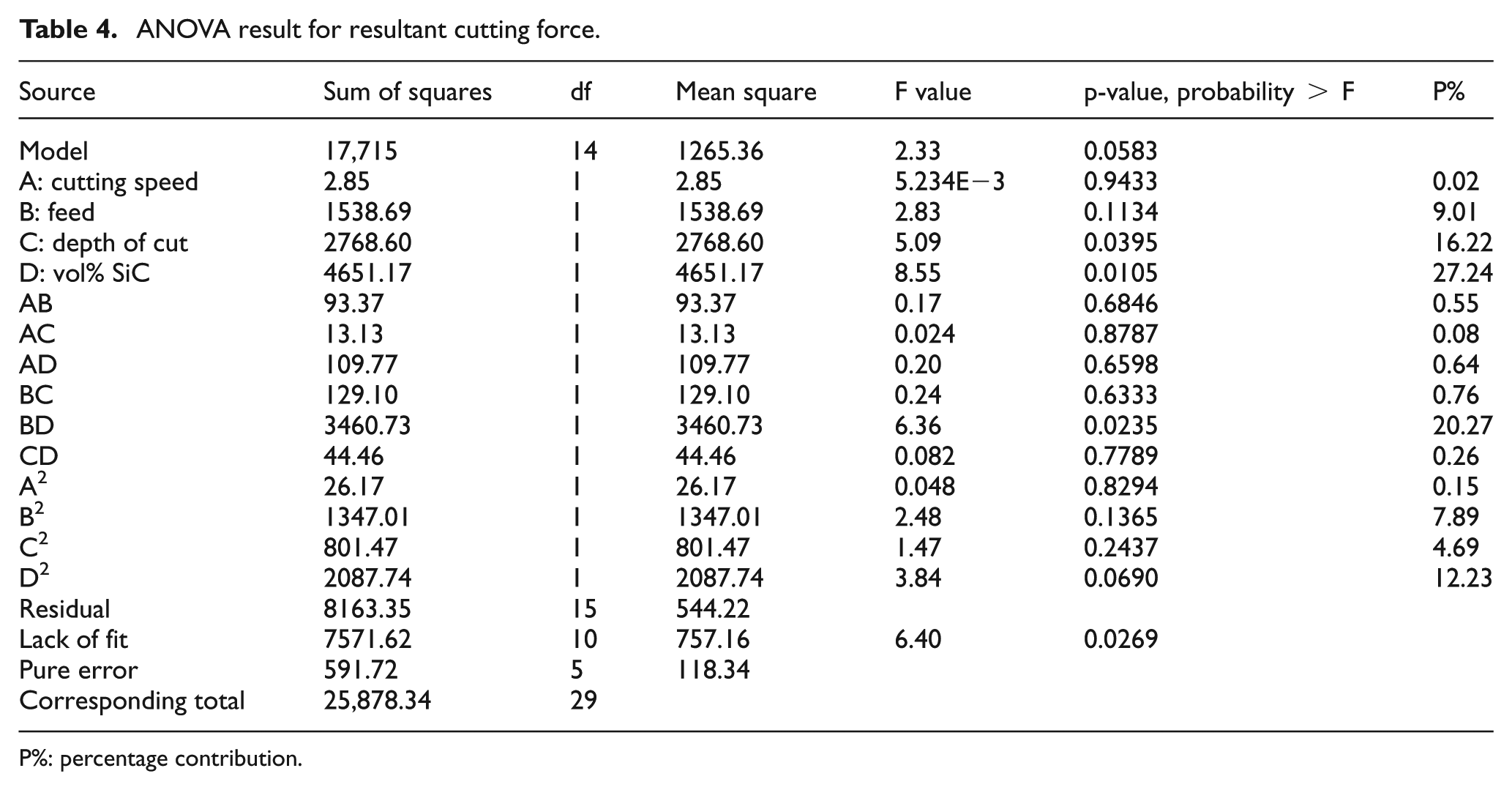
P%: percentage contribution.
From Table 4, the value of probability > F for the model is less than 0.05 (i.e. α = 0.05 or 95% confidence), which indicates that the model is significant. Therefore, depth of cut (C), vol% SiC (D) and interaction effect of feed with vol% SiC (BD) have significant effect. In the last column, % contribution is added in ANOVA table and it often serves as a rough but an effective indicator of the relative importance of each process parameter. 17
Surface plot or contour plots are used for clear understanding of interaction effect of process parameters on responses. It shows the variation between two process parameters on response variable by keeping other process parameters at middle level. Figure 8(a) and (b) shows the response surface plot of significant interaction factors (BD) and (BC), which helps in the prediction of the resultant cutting force at any area of the experimental domain. It is clear from the plot 8(a) that the cutting force increased with the simultaneous increase in feed and vol% SiC particle in the aluminium matrix. Similarly, from the plot 8(b), increase in feed and depth of cut increased the cutting force. The optimum value of cutting force was obtained at middle value of feed, depth of cut and vol% of SiC particles.
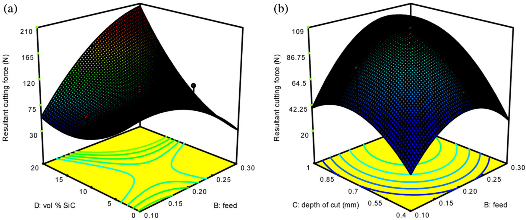
(a and b) Surface plot for resultant cutting force with significant interaction factors.
Modelling of tool–work interface temperature
Temperature generated in the tool–work interface influences the surface quality and tool life in machining processes, particularly in ceramic particle–reinforced composites. The temperature measured in this shoulder end milling process, a portion of the cutter, is not always engaged in cutting operation. In addition, the measurement of temperature is also difficult within a limited microlevel tool–work interface at high-speed tool rotation. Therefore, the temperature measured using non-contact radiation pyrometer between the tool–work interface in this study is the average temperature and the effect of individual process parameter on the temperature is discussed as follows.
The influence of process parameter on tool–work interface temperature during up milling process is shown in Figure 9. It is clear that the temperature increased greatly with the increase in cutting speed and volume % of SiC particles on the composites compared with feed and depth of cut. This is due to the fact that increase in cutting speed increases the cutting energy and the cutting process becomes more adiabatic, that is, heat generated in the shear zone cannot be conducted away during the short interval of time in which the material passes through this zone. Therefore, the temperature also increased. From Figure 9(b) and (c), the tool–work interface length increased with the increase of feed and depth of cut, which increases the friction between the workpiece and the tool, thus increasing the cutting force and temperature. Figure 9(d) reveals that the volume fraction of reinforcement in the matrix increases (also hardness gets increased), which in turn increases the resistance for machining and tool–work interface temperature. A proposed mathematical model for tool–work interface temperature in terms of process parameters is given by
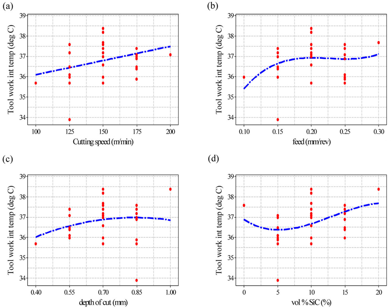
(a–d) Effect of process parameter on tool–work interface temperature.
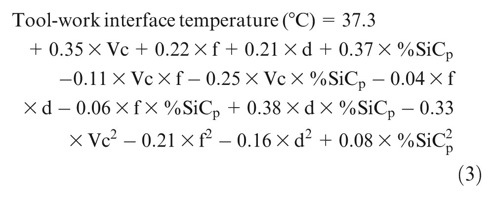
The correlation coefficient (R2) for equation (3) is 0.62 and adjusted R2 is 0.3. The lower value shows the complexity in the accurate measurement of the tool–work interface temperature due to dynamic characteristics of cutting temperature in end milling process than simple turning or other machining process. It can be further improved by conserving higher order response surface equation model, but it may overshoot the prediction. The experimental and the predicted values are plotted for checking the adequacy of the model, which is shown in Figure 10. From the plot, prediction model is closer to the experimental results.
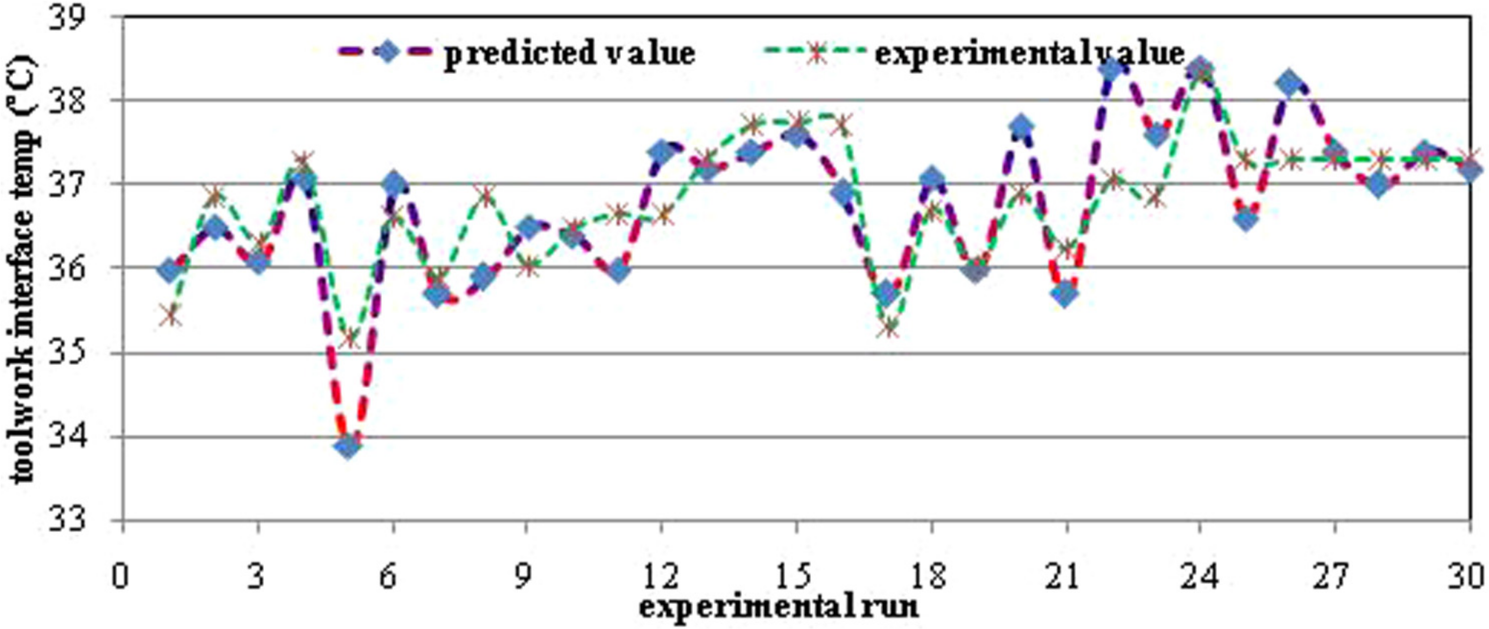
Experimental versus predicted tool–work interface temperature.
The value of probability > F in Table 5 for the model is less than 0.05, which indicates that the model is significant. In the same approach, volume % of SiCp (D) and cutting speed (A) have significant effect on tool–work interface temperature. Among the interaction factors, depth of cut with volume % of SiCp (CD) and cutting speed with vol% of SiCp (AD) are significant, and these are identified only through its higher value of % contribution from ANOVA analysis.
ANOVA result for tool–work interface temperature.

P%: percentage contribution.
Figure 11 shows the interaction between the factors C&D and A&D on tool–work interface temperature predicted using MINITAB 7.0.1 software. From Figure 11(a), lower values of tool–work interface temperature were observed at high value of depth of cut during milling of Al–SiC composites with certain combinations of process parameters only. However, with the simultaneous increase in volume % of SiC in the matrix and depth of cut, the tool–work interface temperature increased. This is due to the increase in hardness of the composites, which resists the shearing of the material and higher friction generated from interaction of cutting tool with SiC particles. Similarly, temperature decreased with simultaneous decrease in cutting speed and SiC particle content on the composites, which is shown in Figure 11(b).
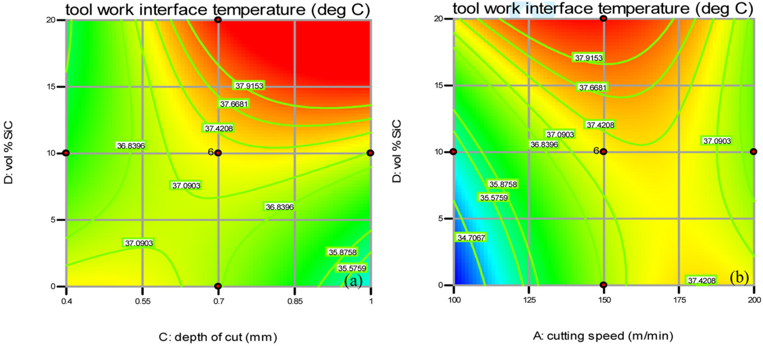
(a and b) Contour plots for tool–work interface temperature with significant interaction factors.
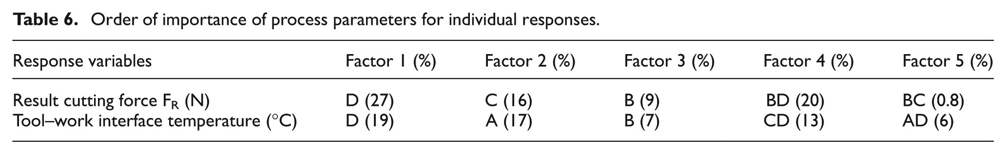
The order of importance of the controllable process parameters to the individual performance characteristics in the CNC end milling process, in sequence, is listed in Table 6. From this table, it was identified that the individual factors, such as depth of cut (C) and volume % of SiCp (D), and the interaction factors, such as feed with vol% SiCp (BD) and depth of cut with volume % of SiC (CD), are the most controllable process parameters for the overall performance.
Order of importance of process parameters for individual responses.
Optimal combination of process parameters
To improve the machinability of the synthesized material during end milling process, optimal combination of the process parameter that affects the individual machining responses such as the cutting force and tool–work interface temperature can be obtained from the main effect plots.
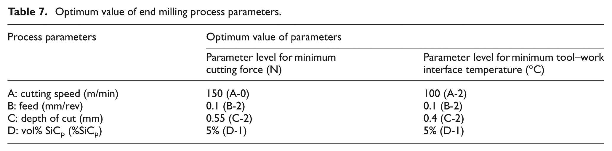
Table 7 lists the optimal process variable levels for improving the individual responses in end milling process. The optimal combination of the process variables thus obtained is found to be within the bounds of the developed mathematical models and process variable ranges.
Optimum value of end milling process parameters.
Conclusion
In this article, end milling studies were conducted on Al A356 alloy with SiC particle–reinforced MMC materials synthesized by vacuum hot-pressing method using uncoated carbide inserts. Central composite experimental design has been employed to conduct the experiments and acquire the experimental observations. A mathematical model is developed using the experimental results to analyse and predict the responses in terms of process parameters. ANOVA was done to investigate the significance and percentage contribution of process parameters on the performance measures. The developed mathematical models were able to predict accurately the relationship between the responses and process parameters.
From the main effect plots, volume % of SiC particles in the composites and depth of cut were found to have high influence on cutting forces. The major factors affecting the tool–work interface temperature are vol% of SiC particle in the composite and cutting speed. The individual prediction models with optimized process parameters obtained from this research work can be used in enhancing the machinability of the composites.
Footnotes
Acknowledgements
The authors thank Dr R. Suresh Kumar, Scientist SG, and his team for synthesizing the composites at SMF, Vikram Sarabhai Space Centre, Trivandrum, Kerala, and Shri. Kasala Narasaiah, Scientist SF, for contribution in conduction machining studies experiments at MME, VSSC (ISRO), Trivandrum, Kerala.