
Abstract
The hardening of rivet hole is a mechanical process used to reduce the level of the resulting stresses due to loading in order to delay the crack initiation and propagation. This technique is used to improve fatigue life and to increase the intervals between structural inspections. The experimental tests have shown that the low residual stresses resulting from cold expansion and the first fatigue cracks are located at the entrance face used for hardening. To solve this problem, a double cold expansion of rivet hole in the opposite direction is proposed. This article presents the results of three-dimensional finite element simulation of double cold expansion process in the opposite direction using Abaqus software. The residual stress distribution in rivet hole of aluminum alloy Al2024-T3 induced by tapered pin was analyzed. The obtained results show that the residual stresses vary through the material depth, are maximal in mid-depth and are strong at the exit face and moderate at the entrance face. They also show that the double cold expansion in the opposite direction increases the residual stresses at the entrance face of the pin, and these stresses reached the values of those generated on the exit face, enhancing the fatigue life.
Introduction
The cold working of a rivet hole is a mechanical technique; an oversized ball or a tapered pin can be forced through the hole locally yielding the material to create a plastic region. The resulting compressive residual stresses around the edges of the hole are very beneficial at resisting fatigue; it can delay crack initiation and slow their propagation. The X-ray diffraction measurements of the residual stresses showed that these stresses were low at the entrance face of the pin and maximum at the exit face.1–3 Fatigue tests of specimens with cold-worked hole have shown the beneficial effects of residual stresses in decreasing the velocity of crack propagation and improving the fatigue life,2,3 and they also showed that the primary cracks were initiated at the entrance face of the pin where the residual stresses are low compared to those at the exit face. 4 For these reasons, and to solve this problem, we proposed in this article a solution of double cold expansion in the opposite direction to the first one to further enhance the level of residual stresses at the entrance face and to improve again the fatigue life. Three-dimensional (3D) model was used for simulating the cold working process using the finite element code Abaqus. The analysis of residual stress distribution was carried out in both entrance and exit faces and in mid-depth of hardened material. The simulation results were compared with those obtained experimentally using X-ray diffraction. 2
Material properties
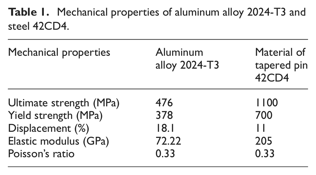
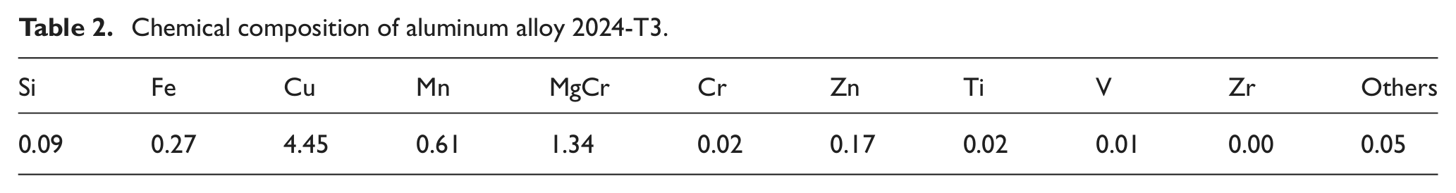
The material used in this study is an aluminum alloy AERO TL 2024-T3. The mechanical properties of this alloy and of the tapered pin are shown in Table 1 and the chemical compositions in Table 2.
Mechanical properties of aluminum alloy 2024-T3 and steel 42CD4.
Chemical composition of aluminum alloy 2024-T3.
Finite element simulation of the experimental process of cold expansion
Experimental process description
To achieve cold expansion, a tapered pin is forced through the hole locally yielding the material to create a plastic region (Figure 1). When the surrounding material, which is elastically deformed, springs back from the expanded state, the yielded material contracts, resulting in compressive tangential residual stress around the hole.5,6 The pin is pushed through the hole using a Instron fatigue machine.
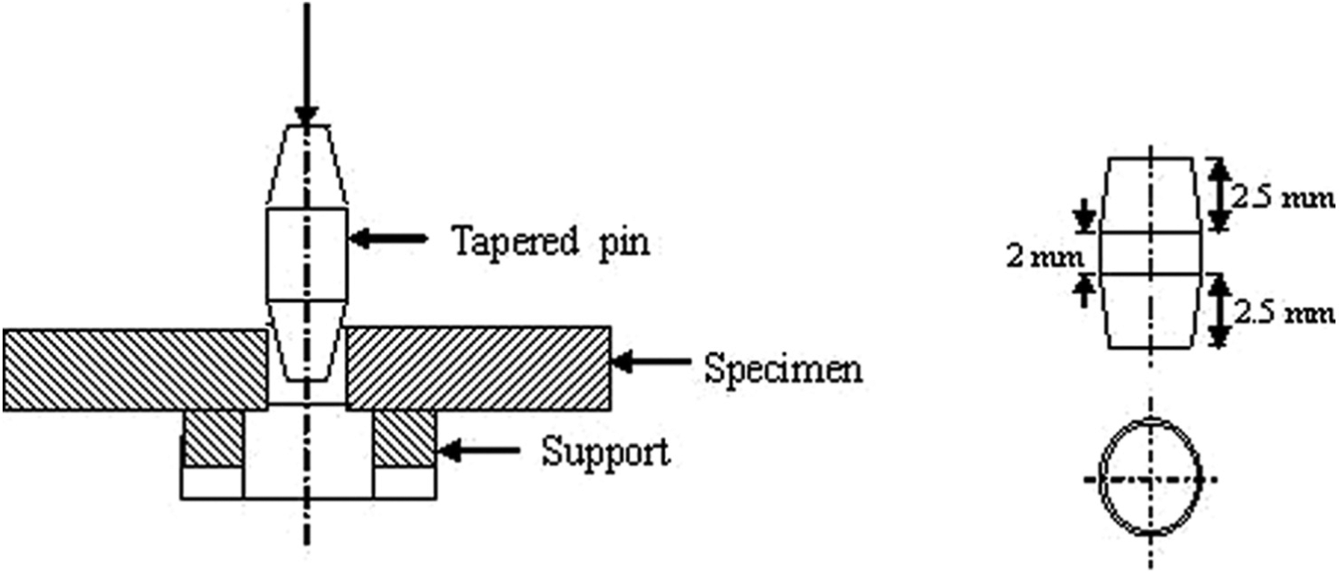
Cold expansion process and length of tapered pin.
Degree of cold expansion
The degree of cold expansion (DCE) is defined by the following equation
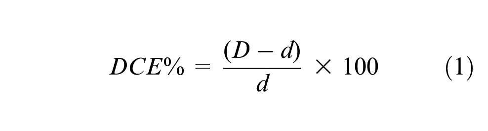
where d and D represent the diameter of the drilled hole and the cylindrical part of the pin, respectively.
Numerical simulation
A 3D model was used for simulating the cold expansion process using tapered pin. The geometry of this model is a rectangular plate (150 mm × 50 mm × 5 mm) with a central hole. The Abaqus finite element code was used to carry out the analysis. We chose an elastoplastic model where the pin is supposed infinitely rigid.
The 3D model is shown in Figure 3 and consists of one set of elements for the plate and another set of elements for the pin. In this study, eight-node linear isoparametric cubic elements were used. This type of element is adapted in the case of elastoplastic calculations.
Only a quarter of the plate and pin were modeled due to their double symmetry with respect to the X–Z and Y–Z planes. The model is immobilized in translation along the x and z axes. It is also immobilized in translation along the y axis and in rotation about the x and z axes. To avoid singularity, the model is finally fixed by z on both sides of the hole on the underside. The mesh is shown in Figure 2; the pin is initially put in contact with the hole at the entrance face of the specimen. The interaction between the surface of the hole and the tapered pin is modeled in three dimensions using a small sliding formulation in which the contacting surfaces can only undergo relatively small sliding relative to each other. With this approach, one surface definition provides the master surface and the other surface definition provides the slave surface. A kinematic constraint that the slave surface nodes do not penetrate the master surface is then enforced. In order to simulate the expansion process, a displacement in the z direction is applied to the pin from the entrance face to the exit face; for this, a load of 10 kN is used. A total displacement of 12 mm of the pin was modeled by 10 successive steps. This displacement is selected to ensure a complete passage of the pin (7 mm in length) through the hole (5 mm in length) (Figure 1). For convergence, each time it is automatically divided into several increments.
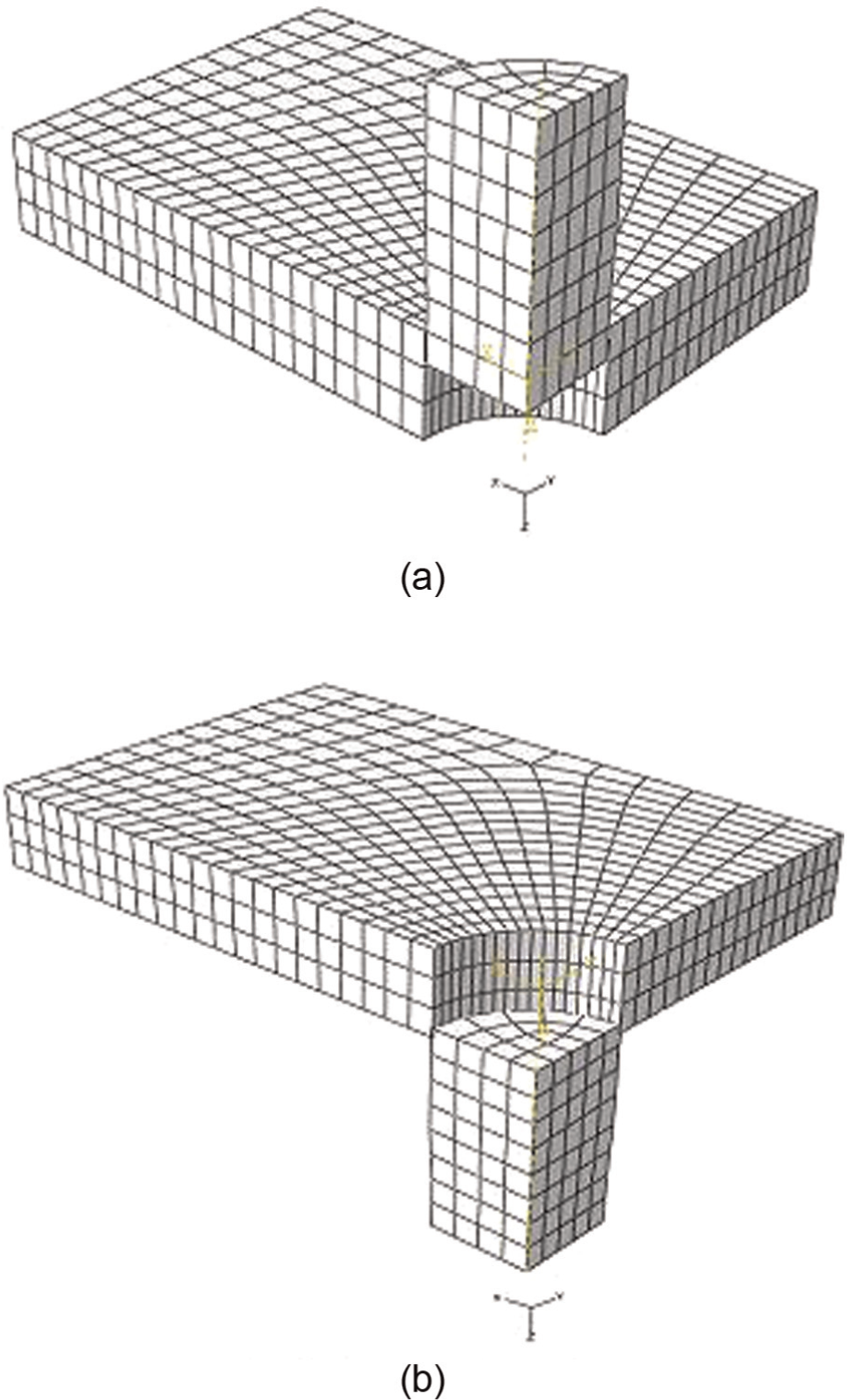
Displacement of the pin through the specimen: (a) entrance and (b) exit of the tapered pin.
Effect of friction coefficient on the variation of residual stresses
To illustrate the effect of friction coefficient between the pin and the hole surface, cold expansion process has been simulated with and without friction coefficient. Figure 3 shows the effect of friction on the variation of residual stresses; a friction coefficient of 0.17 was used. This choice is based on the studies by Chakherlou and Vogwell 3 and Papanikos and Meguid, 7 where the authors have shown that the friction is very beneficial to the expansion effect; they have also shown that the variation of the friction coefficient does not have much influence on the plastic deformation field. They varied the friction coefficient from 0.1 to 0.4, and the difference on the maximum of the equivalent deformation was only 4%. From Figure 3, we observe that the residual stresses resulting from a numerical simulation with friction coefficient are higher compared to those obtained without friction. This finding is consistent with the literature.7,8
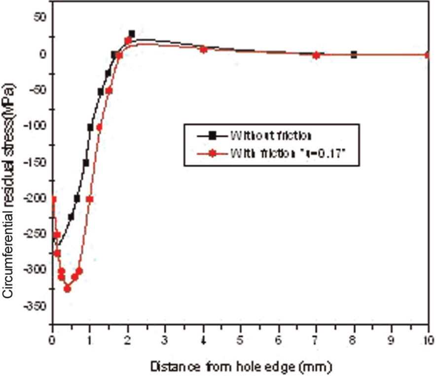
Effect of friction on the variation of residual stresses.
Residual stress variation during the cold expansion process
To get an idea of the variation of residual stresses during the cold expansion process, we followed their evolution in several phases of passage of the pin (20%, 60% and 100%). Figure 4 shows the variation of residual stresses during the process. The DCE was 4.5%. 9 We note that at 20% of the process, stresses are tensile; at 60%, stresses reach the maximum value in tension (408 MPa) and at 100%, stresses are compression and to about −300 MPa at the exit face of the pin. The maximum stress has been recorded in an area between the mid-depth and the exit face of the specimen.
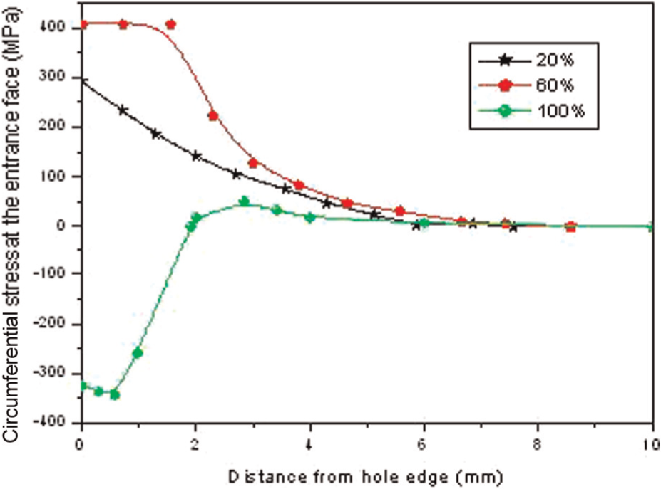
Stress variation during the cold expansion process.
Effect of DCE on residual stress variation through the plate depth
The variation of residual stresses through the plate depth was analyzed for three DCEs (2%, 4.5% and 6%). Figure 5 shows the distribution of residual stresses for single pass of the tapered pin on the entrance and exit faces and mid-depth of the plate. For the three DCEs, the obtained results show that the maximum residual stress is located between the mid-depth and the exit face of the plate. Residual stresses at the entrance face are always lower than those at the exit face, and it has been concluded that the increase in the DCE from 2% to 4.5% increases the level of residual stress about 30% and an increase from 4.5% to 6% increases residual stresses about 10%. We can deduce that the optimum degree of expansion is in the range from 4% to 5%. Experimental results2,4 showed that fatigue cracks are first initiated at the entrance face where the residual stress values are lower than those at the exit face. To solve this problem, we propose a double cold expansion of the hole in the opposite direction to the first one in order to enhance the level of residual stresses on the entrance face of the plate.
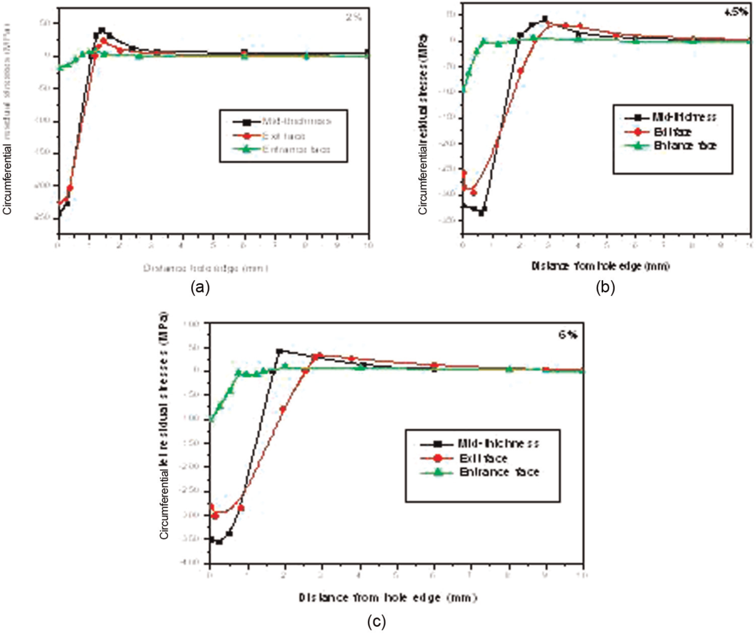
Variation of residual stresses for different degrees of cold expansions (single pass): (a) 2%, (b) 4.5% and (c) 6%.
Comparison of the variation of residual stresses before and after the second cold expansion in opposite direction to the first one
Experimentally, by the X-ray diffraction measurements,1–3 it has been found that residual stresses are low at the entrance face of the pin and maximum at the exit face. Fatigue tests2,3 have also shown the beneficial effects of compressive residual stresses and that cracks are first initiated on the entrance face where the residual stresses are low compared to those at the exit face. Hence, enhancing the level of residual stresses at the entrance face can delay the crack initiation and propagation. To have an idea of the effect of double cold expansion on residual stress distribution, we have simulated again a new process of cold expansion in the opposite direction to the first one for the three degrees (2%, 4.5% and 6%). The residual stresses resulting in the first cold expansion have been maintained. The dimension of cylindrical part of tapered pin is selected to keep the same DCE used in the first cold expansion process. Figure 6 shows a comparison of residual stress distribution before and after the second cold expansion in the opposite direction for the three degrees. Our interest is focused at the entrance face of the first pass; for this and to ensure a good lecture of figures, the curve corresponding to the mid-depth of the plate was removed. We can clearly see the beneficial effect of a second cold expansion in enhancing the compressive residual stresses level on the entrance face used for the first cold expansion. This finding allowed us to delay the crack initiation and propagation first detected (experimentally) on the entrance face used for the first cold expansion process, which can enhance the fatigue life of rivet holes.
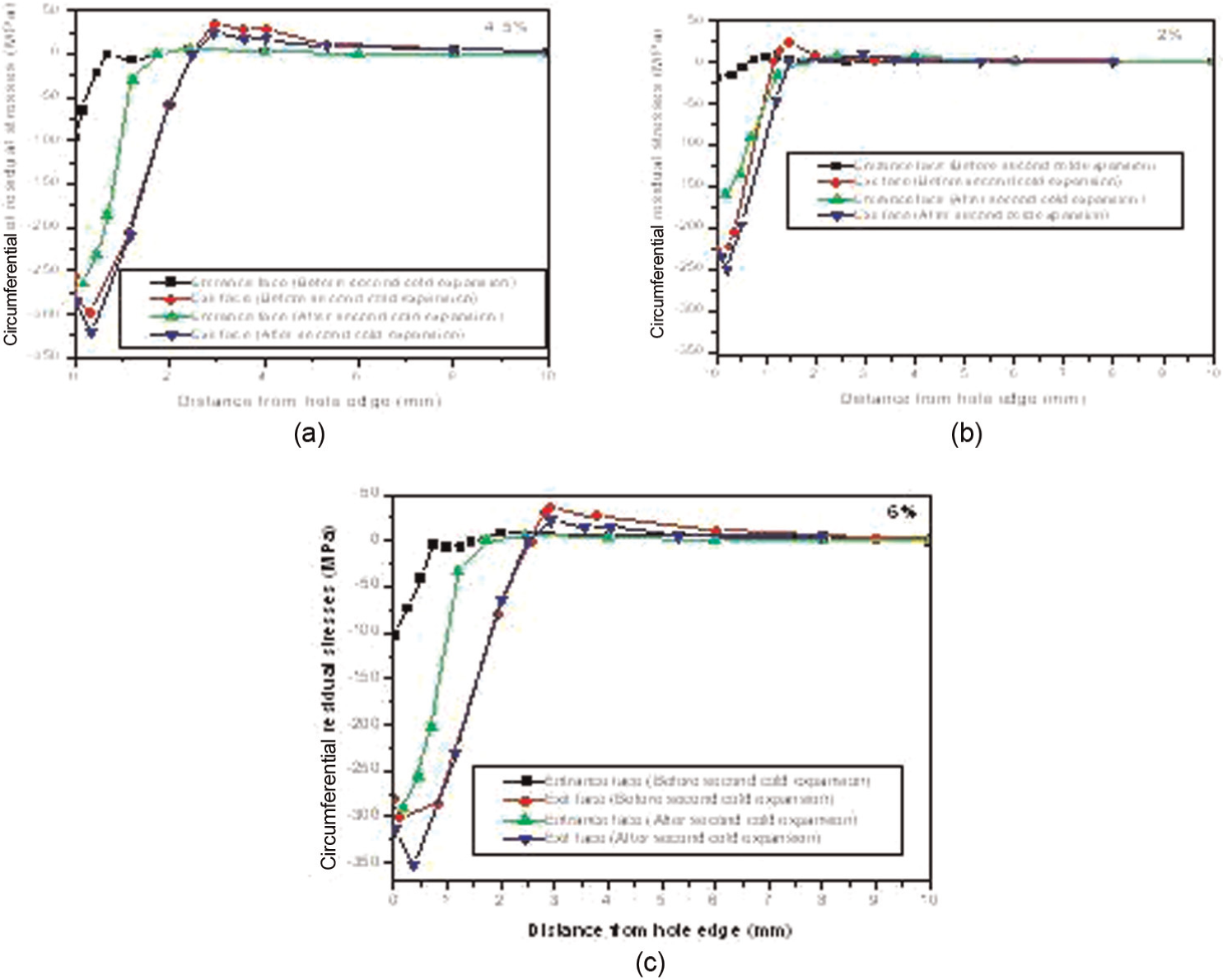
Residual stress distribution for the three degrees before and after the second cold expansion process: (a) 4.5%, (b) 2% and (C) 6%.
Comparison with the experimental results
To validate our numerical model, we compared our results with experimental results obtained by Elajrami; 2 these results are obtained using X-ray diffraction for cold expansion process in only one direction for the degree of 5%. The X-ray diffraction measurements were performed on a four-circle goniometer; the residual stress measurement was made on eight points in the two directions, radial and circumferential, around the hole and on both faces of the specimen (entrance and exit faces). Each measured point corresponds to the center of one irradiated rectangle area of 2 × 1 mm2 (1 mm in the radial direction). The aluminum (422) reflection was used at a diffraction angle of 2θ = 137.44°. This means a depth penetration of 30 µm for the X-ray radiation. Only the circumferential residual stresses are compared because they present largest and important values and their effects are beneficial to the fatigue life. To do, another model with a degree of expansion of 5% was done. Figures 7 and 8 show a comparison of residual stresses obtained experimentally and numerically by finite elements for DCE of 5%. After comparison, the estimated error was not significant; it represents 6% for the entrance face and 4% for the exit face.
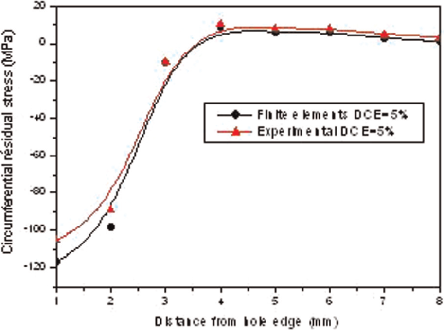
Comparison of residual stresses for a degree of cold expansion of 5% (entrance face).
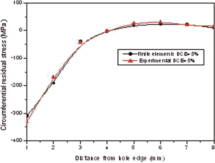
Comparison of residual stresses for a degree of cold expansion of 5% (exit face).
Conclusion
Experimentally, by the X-ray diffraction measurements, it has been found that residual stresses are low at the entrance face of the pin and maximum at the exit face. Fatigue tests have also shown the beneficial effects of compressive residual stresses and that cracks are first initiated on the entrance face where the residual stresses are low compared to those at the exit face. For these reasons, the purpose of this work was to study the effect of the double expansion of rivet hole on residual stress distribution in aluminum alloy 2024-T3 using the Abaqus code. The obtained results have shown that we can enhance the level of residual stresses at the entrance face by double cold expansion process in the opposite direction, which can delay the crack initiation and propagation at this face. Low error rate has been recorded in comparison between experimental results and our finite element simulation for DCE of 5%. In summary, this work allowed us to identify the following deductions and conclusions:
The friction between the contact surfaces (pin–hole) increases the values of the compressive residual stresses.
Residual stresses are not constant; they vary through the depth of the plate.
The area of maximum stresses is located between the mid-depth and the exit face of the plate.
Residual stresses at the entrance face are consistently lower compared to those at the exit face.
Residual stress distribution shows that they are maximal around the hole and minimal away from the hole.
The increase of the DCE from 2% to 4.5% increases the residual stress level about 30%.
The increase of the DCE from 4.5% to 6% increases the residual stress level about 10%.
The optimum DCE is probably between 4% and 5%.
At 20% of the cold expansion process, the stresses are tensile.
At 60% of the cold expansion process, the stresses reached maximum values in tension.
At 100% of the cold expansion process, stresses are compression and to about −300 MPa at the exit face.
To solve the problem of the beginning of crack initiation at the entrance face (observed experimentally), a double cold expansion in the opposite direction to the first one is proposed.
The numerical model was validated by a comparison with experimental results (low error rate).
Footnotes
Funding
This research received no specific grant from any funding agency in the public, commercial or not-for-profit sectors.