
Abstract
Manufacturing efficiency is directly related to the parameters of the process and the material used. In sheet metal industry, the manufacturing process often results in changes in design of the tool to safely stamp the product. These changes in design could occur due to use of a new material with better formability, adjustments to the design of tools and/or the process parameter variation. In order to avoid the trial-and-error procedure, forming limit curve is an effective method for this assessment and is widely used by several authors in recent publications, that is, the use of forming limit curve could be useful to decrease the trial-and-error procedures and tool-developing expenses. Despite being widely used in the industry, a process parameter that has been barely researched is the influence of blankholder force on the drawability of advanced high-strength steels, which contains multiple phases on microstructural level. The main aim of the present study was to analyze the influence of the blankholder force on the formability of DP600 steel. Blankholder forces of 130, 80 and 58 tons were considered. The experimental results led to a detailed understanding of the blankholder force influence during the process. The blankholder force variation promoted different material flow strain rates in the flange during the stamping—higher strain rate increased the bending effect on the die radius. As a result, an experimental approach that allows the blankholder force determination as a function of the different strain rates of the flange flow of the stamped sample was proposed.
Introduction
The automotive industry is a major consumer of high-strength steels and therefore a major driving force for the development of new materials and technologies. In recent decades, the increasing competition and growing demand for lightweight, high-performance and crash worthiness structures in automotive vehicle forced steel industry, automakers and the scientific community to focus on more efficient production. As a result, a significant increase in the use of steel structures has been observed in automobiles over the last decade. Thus, a better understanding of the conformability of these materials is necessary to reduce costs and optimize the process.
Formability evaluation is complex due to several process parameters that individually or in combination plays an influential role in sheet metal stamping process. Researchers are continuously trying to understand the advantages and limitations of these parameters.
Kim et al. 1 reported an analysis of the mechanical properties and drawability of low-carbon steel (LCS) and dual phase steel (DP590) formed with low strain rates (from 0.001 to 0.01 s−1) and high strain rates (from 0.1 to 100 s−1). Under these conditions, an observation on an increase in the elongation to fracture of LCS was made, while DP590 showed a decrease in the elongation when formed at higher strain rates. According to the authors, the elongation and hardening coefficient gradually decreases with increasing strain rate. The value of the anisotropy coefficient—measured by high-speed cameras—was also sensitive to the variation in strain rate.
Huh et al. 2 carried out tests by varying the strain rate—from 0.003 to 200 s−1—using transformation induced by plasticity (TRIP) and DP steels. In their work, TRIP600, TRIP800, DP600 and DP800 steels were characterized by uniaxial tensile tests. The experiments pointed to an increment in ultimate tensile strength as the strain rate increases. In addition, the elongation at fracture and formability of TRIP steels showed better results than DP steels under intermediate strain rates. Another aspect examined by Huh et al. 2 was the influence of prestrain of 5% and 10% applied to the samples. In this condition, the results showed a variation in the mechanical properties for strain rates above 1 s−1; therefore, the ultimate tensile strength and yield stress were increased due to the prestrain imposed.
Kim et al. 3 conducted a study of advanced high-strength steel (AHSS) failure behavior trying to describe the onset of shear fracture. They carried out experimental and numerical studies, using DP590, DP780 and DP980 steels, and tried to accurately predict the onset of crack. In their work, they proposed a bending model for the prediction of failure—by numerical simulation—using a thermomechanical approach.
Kadkhodapour et al. 4 performed uniaxial tensile tests using DP800. The tests were interrupted at various stages before the rupture of the sample. They observed that some fractures were nucleated in ferrite–ferrite grain boundaries and occurred in the vicinity of martensite particles. In the ferrite–martensite grain boundaries, two onsets of crack patterns were observed. In the first pattern, a crack formed initially in the grain boundaries of ferrite–ferrite spreads to meet the grain boundary of ferrite–martensite. The second pattern was named normal separation of the ferrite–martensite grain boundaries, and the crack pattern was credited to the incompatibility of stress–strain concentration. Thus, the failure pattern was not deviated from the classical ductile fracture.
Despite the great importance for the stamping, the influence of blankholder force (BHF) has been barely investigated in the literature. Altan et al. 5 showed a tooling model that uses springs—as a blankholder—to generate the BHF during the stamping process. This model represents the tooling most used in the industry.
According to the ASM Handbook, 6 the main objective of the BHF has been to prevent wrinkles during the process; however, it can also interfere in the fracture mode. Furthermore, ASM Handbook 6 mentions that there are no precise equations that could permit a satisfactory quantification of BHF and, normally, it is determined empirically. In this case, an advice is reported: the BHF should be, roughly, one-third of the force required for stamping.
In order to advance the subject a little further and as a contribution to the research gap still present in the state of the art, the current work aimed to analyze, via experimental tests, the drawability of DP600 steel when stamped with different BHF—the complete restriction of the sheet until a virtually free material flow (without any restrictions). In order to do so, the next sections will study the influence of the BHF on the DP600 formability. Finally, based on such results, an experimental approach that allows the BHF determination as a function of the different strain rates of the flange flow of the stamped sample (V2) was proposed.
Experimental procedure
The sheet material used was 2-mm-thick, AHSS DP600. This material was also studied by DeArdo et al., 7 Curtze et al., 8 Farabi et al., 9 Uthaisangsuk et al. 10 and Bettaieb et al. 11 The uniaxial tensile tests were performed according to NBR 667312 and NBR 816413 standards, and five specimens for each sheet rolling direction were used.
The tests to determine the forming limit curve (FLC) were performed according to the model originally proposed by Keeler 14 and extended by Goodwin, 15 Woodthorpe and Pearce, 16 Narayanasamy and Sathiya 17 and Narayanasamy et al.18,19 The tests were conducted with a hemispherical punch of radius 50 mm and draw beads in the blankholder, as described by Nakazima et al. 20 Specimens with 200 mm of length and 200, 175, 150, 125, 100, 75, 50 and 25 mm of widths were used to create the FLC. No lubrication was added to the tooling or specimens. The obtained DP600 FLC was the base curve for evaluating the influence of the BHF variation on the formability.
In order to evaluate the influence of BHF, a modified Nakazima tool has been used—without draw bead. The tool design was based on the model proposed by Altan et al. 5 The samples’ dimensions were 200 × 200 and 150 × 200 mm, and BHFs of 130, 80 and 58 tons were considered. The loads were chosen in order to have a complete restriction of the sheet until a virtually free material flow during the process. After the tests, the maximum true strains (major and minor) for the material rupture were measured and the values were compared with the FLC.
A 4.2-mm-diameter circles grid was imprinted on the test specimen’s surface. The grid was plotted using an electrolytic process. Figure 1 illustrates the test specimens used to evaluate the BHF influence and the measured points of true strains. The measurements were taken on the opposite side of the fracture; therefore, the measurements in cracked circles were avoided. The printed circles were measured with a calibrated transparent mylar tape with diverging traces (the method was previously calibrated at an optical profilometer). An average of three test specimens for each one of the experimental conditions was evaluated.
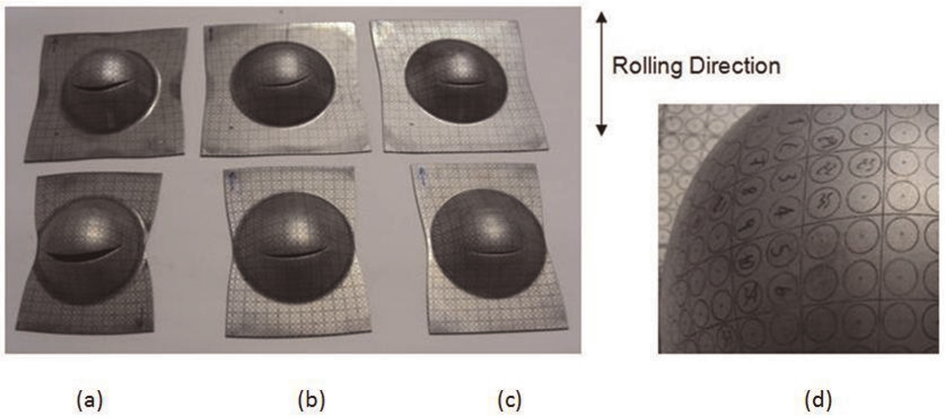
Test specimens used to evaluate the BHF influence: (a) 58, (b) 80 and (c) 130 tons and (d) the measured points of true strains.
Results
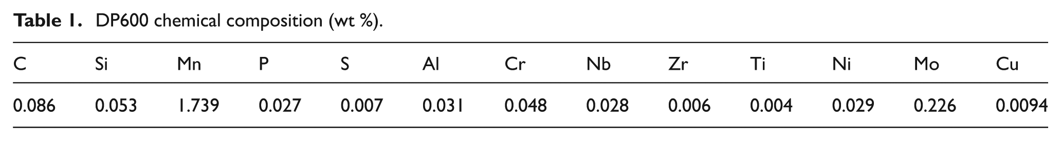
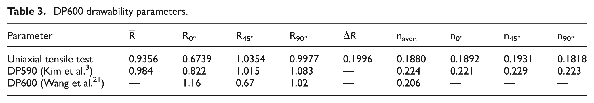
The DP600 chemical composition, mechanical properties and drawability parameters are shown in Tables 1–3. Figure 2 illustrates the DP600 FLC and the data obtained with the loads of 130, 80 and 58 tons, respectively (stretching side of the FLC).
DP600 chemical composition (wt %).
DP600 mechanical properties.
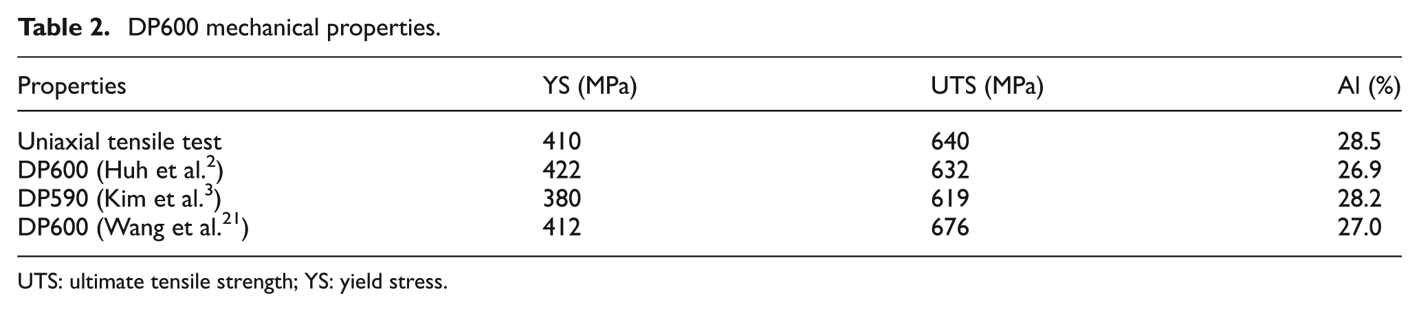
UTS: ultimate tensile strength; YS: yield stress.
DP600 drawability parameters.
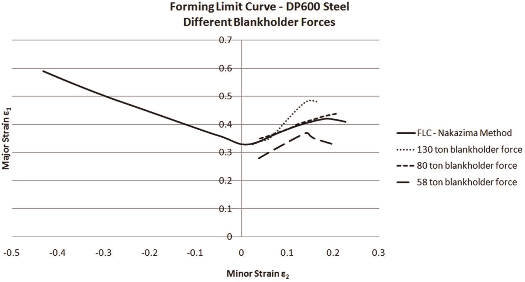
DP600 FLC and the data obtained with BHFs of 130, 80 and 58 tons.
In order to obtain the punch displacement at the sample rupture point and the total stamping time, a programmable logic controller (PLC) has been used. Thus, the total time of stamping (ts) during the forming with the BHFs of 130, 80 and 58 tons was tabulated. The data were also obtained for 35 tons, corresponding to the minimum force required for stamping. Table 4 shows the values of material displacement (Δdf) and the material flow speed in the flange (V2) of the specimens—for each condition of the BHF.
Stamping time, sheet displacement and material flow speed in the flange for different BHF conditions.
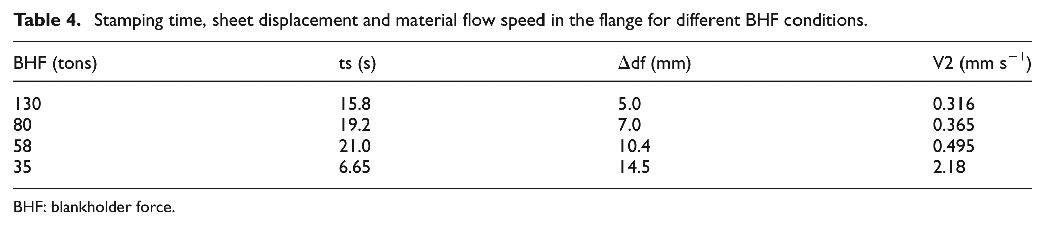
BHF: blankholder force.
The material displacement in the flange of the sample (Δdf) was obtained by direct measurement of the specimen. This measurement corresponds to the sample reduction in the region of action of the BHF—in the direction of a radial flow line of the material. The material flow speed in the flange (V2)—which according to Kim et al. 3 can be understood as the strain rate in this region—was determined by dividing the displacement (Δdf) by the total stamping time (ts). The division of the punch displacement (stamping depth) of each sample tested by the total stamping time also allows the determination of the stamping speed (V1), corresponding to 2.5 mm s−1.
Figure 3 shows the BHF variation as a function of the material flow with different speeds in the flange that can be assumed as strain rate in the flange (V2).
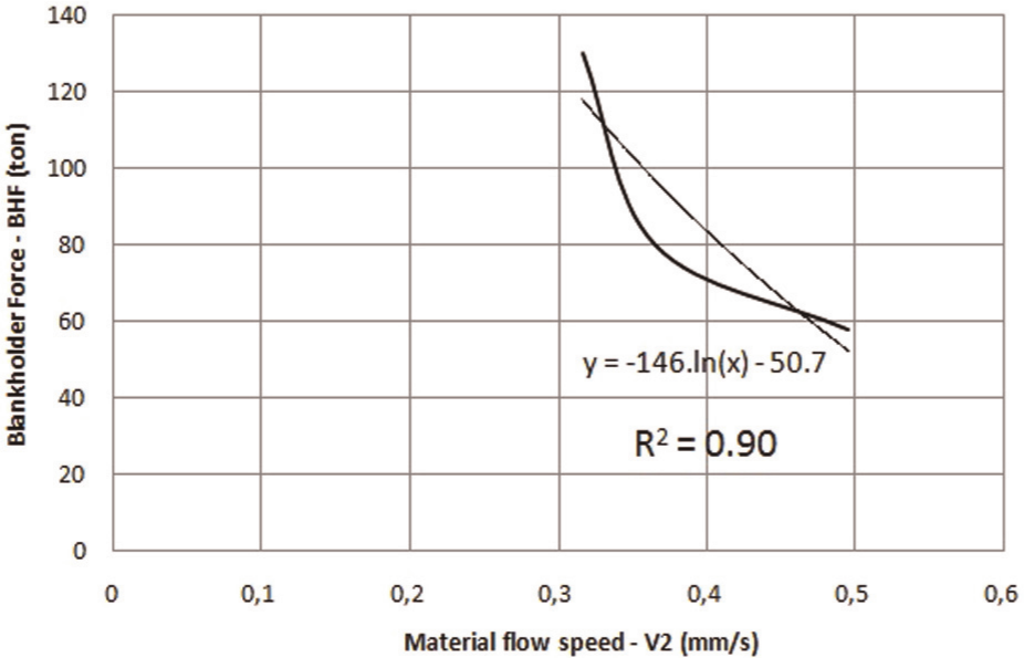
BHF variation written in terms of material flow speed in the flange.
Through the trend line, the mathematical equation of the corresponding curve (equation (1)) can be determined

From equation (1), two other values of BHF can be calculated. Considering a total constraint condition for the sample in the flange, the strain rate V2 becomes 0.01 mm s−1—approximately to zero strain rate—which would be represented using BHF of approximately 621.7 tons. For the second condition, the BHF can be determined taking into account the value of the maximum strain rate of the material (equation (2))—determined by the bending test proposed by Kim et al. 3
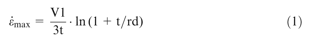
Using speed V1 of 2.5 mm s−1, sheet thickness (t) of 2 mm and radius of the shoulder of the die (rd) of 10 mm, a maximum strain rate of 0.076 s−1 can be calculated. This value is equivalent to the BHF of 325.5 tons—by the trend line of equation from Figure 3. Thus, by adding the values of strain rates (V2) for the BHFs of 325.5 and 621.7 tons, the diagram of BHF could be determined as a function of the material flow strain rate variation in the flange (V2), shown in Figure 4.

Material flow speed in the flange with BHFs of 325.5 and 632.9 tons.
Discussion
It is worth noting that for the BHF of 130 tons, the FLC has shifted up in the stretching region—strain mode for the specimens of 200 × 200 and 150 × 200 mm. This trend characterizes an improved drawability of the material in about 22%, that is, the steel reached a higher strain level until its final rupture. In this load condition, a slip of 5 mm of the material in the flange area was observed—BHF area of actuation. This was the closer condition to full lock, which promoted the sample deformation mainly in the sheet thickness.
Traditionally, it can be said that a small decrease on the restriction imposed by the BHF allows an improvement on the formability. However, with the load of 80 tons—lower load—a decrease in drawability was observed. It can be noted (Figure 4) that the FLC in this condition was almost superimposed on the FLC originally obtained by the Nakazima method, that is, the BHF reduction that gave greater freedom to material flow during the stamping is not meant to formability gain. Thus, the formability gain observed with the BHF of 130 tons was lost when the restriction was further decreased by reducing the BHF to 80 tons.
The use of BHF of 58 tons allowed an even greater slipping of the sample during forming in a similar way as aforementioned. In this condition, a significant reduction on the DP600 formability was observed. According to Figure 2, the FLC obtained with BHF 58 tons was below the curve obtained by the Nakazima traditional test—representing a loss of approximately 8% in the formability of the material.
It should be noted that the drawability of DP600 steel suffers a very significant influence of BHF. It is evident that there is an optimal value of force near 130 tons, which represented a gain in formability compared with the condition of total locking of the material. In practical situations, often the BHF is set at the minimum necessary force to avoid wrinkles in the flange—wondering to get the drawability improved by the minimal restriction imposed for the material flow. This consideration could be mistaken for DP600 steel. The possible explanation for the decrease in drawability as the BHF was reduced to 80 tons and then to 58 tons could be the change in the type of material failure due to the increase of the material flow over the shoulder of the die—the material mode of failure is being studied by the authors.
As the material has more freedom to flow during forming, it becomes more pronounced the effect of bending on the shoulder of the die. At this point, a weakening of the material due to bending could be observed—as the bending is more pronounced, the steel approaches/passes its limit of ultimate tensile strength showing a localized necking. As the bended region moves into the die—as the sheet is pushed by the punch—this point could become sensitive to fracture by shear fracture. This stamping behavior explanation is supported by the bending model reported by Kim et al. 3
With the samples formed with larger BHF, the material region that suffers bending moves very little into the cavity of the die and the rupture does not occur in the bended region. In this case, the material failure does not occur by shear fracture, that is, the rupture is reached as a function of the stretching of the sheet. This can be corroborated by the uniaxial tensile test findings. It was observed that during the uniaxial tensile tests, the DP600 presented good formability showed by the hardening coefficient. Certainly, the adequate value of the hardening coefficient together with the, still present, freedom of material flow with BHF of 130 tons helped in the improvement of formability.
Conclusion
The BHF has a direct influence on the formability of DP600 steel. In practical terms, there is an ideal value of BHF for the DP600 stamping. In summary, a limit level of material flow was found in order to have improved formability, and this finding was corroborated by the FLC raising. In contrast, lower BHF—below a certain threshold—leads to a material loss of formability due to the increased material flow during stamping (since there is a commitment of the ductility with the occurrence of shear fracture). All this information—appropriate BHF determination—can be helpful in reducing the trial-and-error procedures since in many cases, a loss of formability by reducing the BHF during the process is not expected. The proposed experimental approach for BHF determination can be helpful in determining the efficiency in the manufacture. However, it should be highlighted that the results of the present work are only valid for the stamping of DP600 steel.
Footnotes
Funding
This research was supported by USIMINAS—Usinas Siderúrgicas de Minas Gerais S/A (DP600 supply)—and CNPQ (Brazil).