
Abstract
The structural design and flight stability characteristics of micro air vehicles have received much attention due to its low Reynolds number. Compared with fixed-wing aircraft, hovering ducted-fan micro air vehicles with vertical takeoff and landing and hovering capabilities have promising prospect. In this article, a flexible membrane and inflatable structure has been used as the aerodynamic shape of an aircraft model. Its advantages have been analyzed and verified by fluid–structure interaction based on finite element method. The flight stability of hovering micro air vehicles has also been investigated based on the theory of motion of structure. In order to improve the flight stability of the designed hovering micro air vehicle model, the effects of geometrical parameters and materials have been analyzed through an orthogonal experimental design. Based on the optimized results, the aircraft prototype has been manufactured for experimental test. The elastic deformation produced on its flexible membrane structure is obtained by stroboscopic stereo imaging method and a purpose-built experimental environment. The numerical simulation results indicated that the thickness of membrane and material of vertical duct have significant effects on the micro air vehicle flight stability and disturbance resistance ability. The results have confirmed that the flexible aerodynamic mechanisms produced by the aeroelastic deformation of spherical membrane can enhance the micro air vehicle stability.
Keywords
Introduction
Micro air vehicles (MAVs) usually refer to autonomous size-restricted unmanned aerial vehicles (UAVs). The diameter for each direction is less than 150 mm, and cruising speed range is between 30 and 60 km/h. With the development driven by military, government and industries, the MAVs have been used for remote monitoring, aerial photography and observation of hazardous environment. According to the different structures, MAVs can be classified as fixed-wing craft, rotary-wing craft and flapping-wing craft. Fixed-wing crafts have higher forward speed and realize long distance flight. Rotary-wing crafts have the capability of hovering and moving in any direction, thus especially suitable for indoor applications, 1 a property fixed-wing crafts do not have. Compared with the previous two types, flapping-wing crafts seem to have better manipulability and aerodynamic characteristics, which come from the inspiration of flapping flyers.2,3 However, the unsteady aerodynamic characteristics of flapping-wing mechanism and related techniques have not yet matured and, indeed, there are still good research opportunities.4,5
A ducted-fan hovering rotary-wing MAV will be discussed and analyzed in this article due to its flexibility. There are several representative rotary-wing MAVs reported in the literature. Kolibri micro-helicopter built by Lutronix Corporation has cylindrical structural design and rotors installed at the top of the aircraft. T-Hawk ducted-fan MAV designed by Honeywell 6 has good antidisturbance performances and is able to complete flight missions under 20 m/s airflow speeds. Mesicopter flight vehicle from Stanford University 7 has a 16 × 16-mm square frame and four-rotor horizontal layout with 1.5 cm rotor diameter. Quadrotor helicopter developed by Massachusetts Institute of Technology (MIT)8,9 has already achieved autonomous navigation and unknown indoor environments mapping with its three-dimensional (3D) laser range finder sensor. Another rotary-wing MAV is Samarai, which was published by Lockheed Martin10,11 at the Annual Conference held by Unmanned Vehicle Systems last year. Its design inspiration came from the rotating phenomenon of maple seeds. All vehicles mentioned above rely on their active flight control method and control strategy to realize stability performances. There are very few literatures on flight stability control based on adaptive aerodynamic shape for hovering MAV.
MAVs usually have a Reynolds number in the range of 103–105, quite similar to birds and insects. 12 Aerodynamic problems in low Reynolds situation have become a significant research issue. The research on the outstanding features of natural flyers seems to be very helpful to complete structural design, investigate aeroelastic properties and analyze unsteady aerodynamics for MAVs. 13 Usually, the wings of insects and birds are not absolutely rigid. For example, some insects deform their membrane structures as a response to airflow pressure and birds can also control the shape of their feathers to adjust the aerodynamic properties. All these flexibilities have functions to change flow structure and pressure distribution around the flyer body.14,15 This biological inspiration from natural flyers has been applied in the design and fabrication phases of MAVs in recent years, 16 and the main purpose is that aircraft structures should be able to resist disturbances caused by airflows or accelerations of themselves. 17 The flexibility of aeroelastic structure allows it to deform locally to accommodate the spontaneous changes, accomplish station keeping and produce a more stable flight. 18
This article presents the analysis and design of a ducted-fan hovering MAV with a lightweight membrane and inflatable structure. In section “Structural designed model,” the structural design concept including geometrical parameters and optional materials is discussed. In section “Fluid–structure interaction,” the interaction between aircraft’s flexible structure and aerodynamics is introduced based on finite element method. In order to find the optimal designed model and improve the properties of aircraft such as flight stability and aerodynamic characteristics, an orthogonal experimental design (OED) and related analysis are presented in section “OED.” In section “Results and discussions,” the numerical results from the OED are discussed. In section “Experimental verification,” the experimental environment and method used in the experimental verification are briefly addressed. The conclusions are then drawn in section “Conclusions.”
Structural designed model
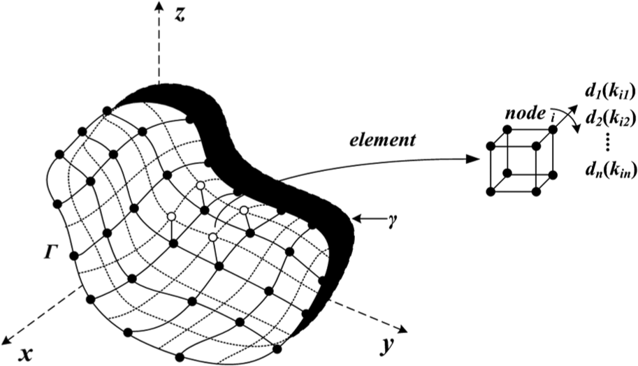
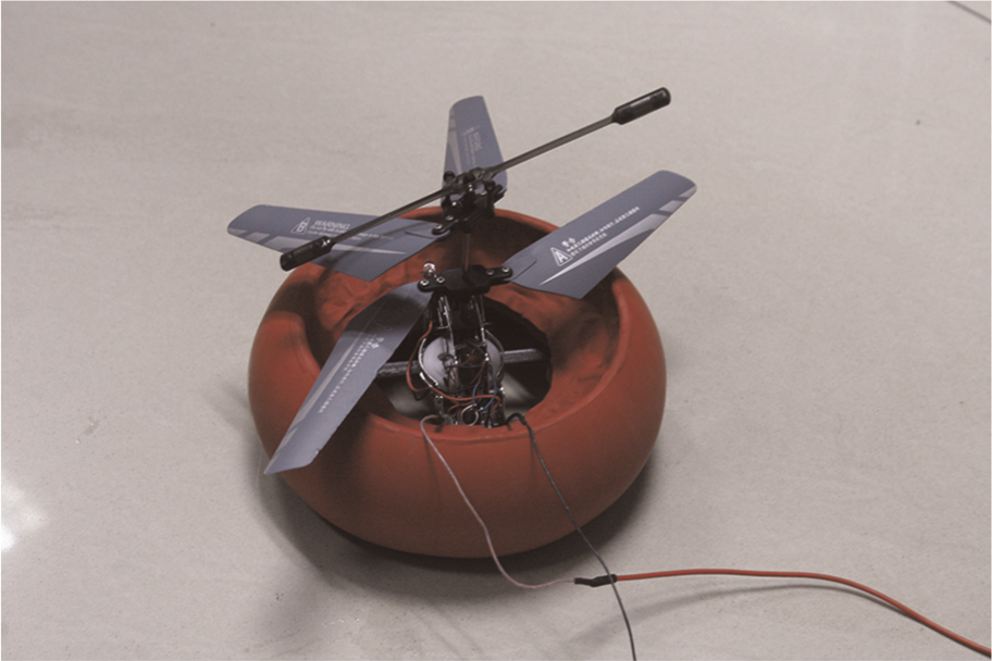
A similar ducted-fan hovering MAV is proposed in this article, as shown in Figure 1. The designed model is composed of lifting system, cylindrical vertical duct and spherical membrane structure. The lifting system includes a control circuit, a propulsion motor and coaxial twin rotors. Apart from the rotor blades, the lifting system is fixed inside the cylindrical vertical duct, and outside this is a flexible membrane structure. As a result, a closed air bag is formed between the membrane structure and vertical duct structure. This aerodynamic design is inspired from the membrane structure at the root of the wings of natural flyers that produces passive deformation under airflow pressure and utilizes unsteady aerodynamics to alleviate airflow disturbance on the body.
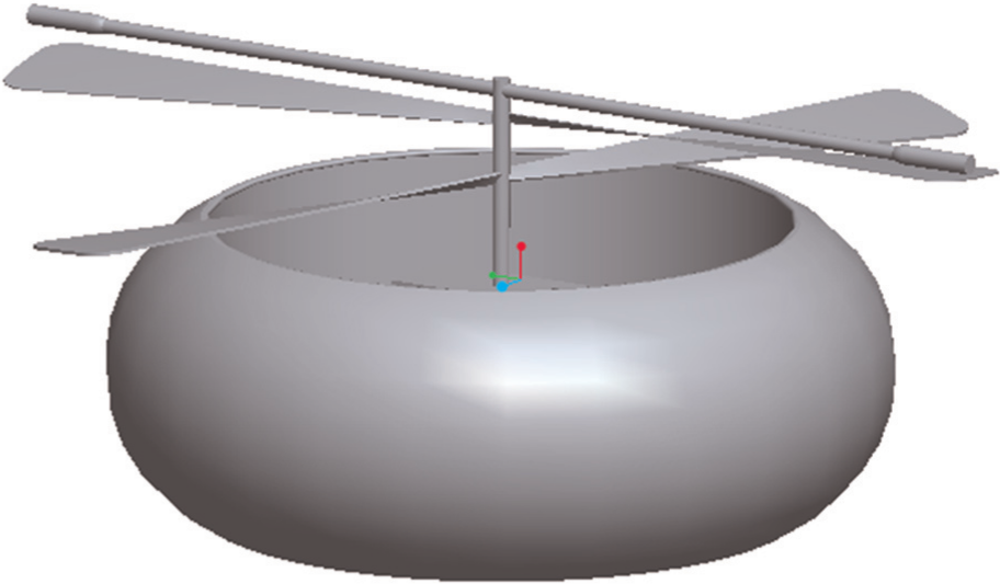
Hovering flying model with flexible aerodynamic shape.
Unlike general ducted-fan MAVs’ layout, the rotor blades of the proposed flying model are outside the vertical duct. The most important considerations for this design are twofold. First, this research focuses on the antidisturbance performances of flexible aerodynamic shapes in terms of spherical membrane detection and flight stability study. Second, due to the constrained space of flow disturbance test environment, the structure of the proposed model is much more compact and thus convenient to complete the test tasks.
The main structural design of an aircraft will significantly determine its flight stability, control characteristics, aerodynamics and speed. The aerodynamic layout of the proposed membrane structure is presented in Figure 2. Four geometric parameters have been selected to investigate the effects they may have on the flight stability of the whole structure, including the external radius R of the membrane structure, the internal radius r of the cylindrical vertical duct, the height H of the aircraft and the thickness t of the membrane.
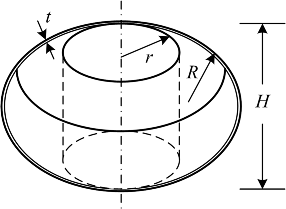
Designed parameters of the model.
The choice of the aircraft’s material also affects its flight performance. In traditional aerospace industry, aluminum alloys are typically used in aircraft structures. 19 Among these, aluminum alloy 2024 is one of the most used materials in aircraft structural components owing to its high strength-to-weight ratio. 20 In the last decade, composite and elastoplastic materials have been given more attention in the aerospace industry because of their high strength and lightweight. A fixed-wing prototype designed by Ifju et al. 21 utilized a combination of inspired design from the natural flyers and composite materials, with a flexible wing constructed with a carbon fiber skeleton and an extensible latex rubber membrane. This unique design can provide some advantages over their rigid counterparts because the flexible mechanism has an ability to adapt to the coming airflow to keep a smoother flight.
Since the Reynolds number is given by
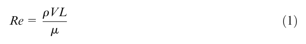
where ρ is the density of air, V is the relative velocity of vehicle, L is the maximum diameter of the structure and µ is the dynamic viscosity, the Reynolds number can be calculated in the range of 4 × 10⁴–4.4 × 10⁵, which is quite similar to that of nature flyers. Compared with those normal size airplanes, this low Reynolds number is a fundamental restraining factor of structural dynamics and fluid dynamics for micro aircraft. Due to their small size and lightweight, MAVs are more sensitive to atmospheric disturbances. It is therefore important to improve MAVs to have adaptive control capability in unsteady flight environment.
Fluid–structure interaction
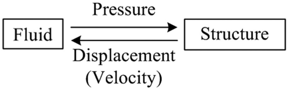
Natural flyers actively control the shape of their wings or feathers to accommodate surrounding flows, and sometimes, their membrane structure on the body may also be deformed adaptively. For example, when the airspeed of wind gust changes, bats accomplish smooth flight by extending or retracting the membrane to decrease or increase lift, using a passive adaptive mechanism for station keeping. This phenomenon can be explained to some extent by the research of multifield interaction in which the information transmits between different fields. In this study, the interaction between the spherical membrane and airflow disturbance is a fluid–structure interaction (FSI) problem, which usually exists in the combinational field of fluid dynamics and structural dynamics. Flow pressure causes the structure surface to move or deform, which, in turn, changes the flow pressure distribution around the vehicle. As shown in Figure 3, the coupling phenomenon is transient and the pressure on the structure surface and the displacement (deformation) on the interface are continuous.
Interaction model between fluid and structure.
A substitute structure that has a finite number of degrees of freedom to replace the continuum is used for approximate solution. A finite element model is shown in Figure 4. 22
A finite element model.
For each element with m nodes, n is the number of degrees of freedom,
For a deformable model, {D} is the structure displacement vector,
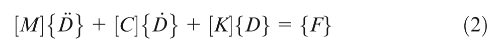
where [M] represents the structural mass matrix, [C] is the matrix of damping,

Suppose under certain external force

Here
Ideally, if a flight vehicle has good stability, its body would hold in a fixed position in the air. Therefore, in the simulation, the vertical duct of the model is set with fixed support and the spherical membrane surface is defined as fluid–structure interface. Unstructured mesh method is utilized to generate volume mesh for computational fluid air, which is denser near the interface and sparser away from the surface. k-Epsilon is adopted as fluid turbulence model. Based on Navier–Stokes equation of the unsteady viscous flow, auto time step is set as 0.05 ms in arbitrary Lagrangian Eulerian dynamic mesh finite element simulation. Boundary conditions such as inlet, outlet and walls are set in the fluid area, respectively, and a horizontal airflow of 8 m/s is inserted in the entrance.
OED
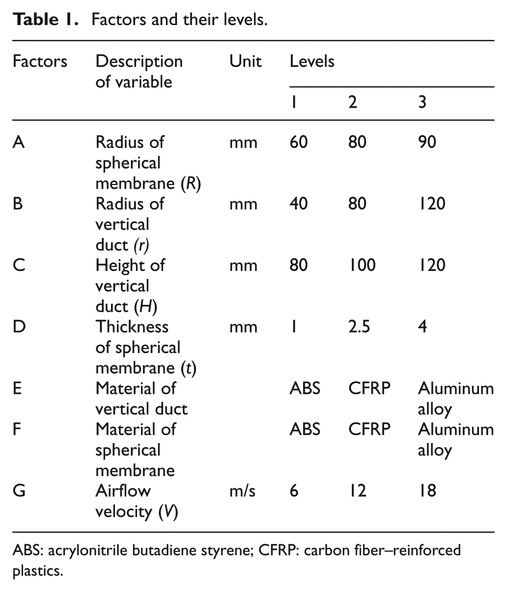
This section is concerned with how to select and utilize structural parameters, materials as well as environmental conditions during the design process to improve flight stability. Since the deformation produced on the membrane structure and the pressure force produced on the aircraft are influenced by various geometric parameters and material properties, an OED is used to determine the significant factors and the best design combination in terms of flight performance. OED methods are usually utilized in conventional aircraft design and performance analysis, such as stealth shape optimization, 25 rotary damping coefficient estimation of aircraft wings 26 and so on. In the study of small-scale flight vehicles, especially hovering MAVs, using OED to analyze and improve flight stability is not common. Based on the finite element method, the effects of the selected factors on the elastic deformation d will be calculated and investigated. The results and process of flight stability improvement will provide references for MAV design in the future.
In order to investigate the effects of geometric parameters and material properties on the deformation and further to optimize the MAV’s structural design, an
Factors and their levels.
ABS: acrylonitrile butadiene styrene; CFRP: carbon fiber–reinforced plastics.
Mechanical properties of candidate materials.
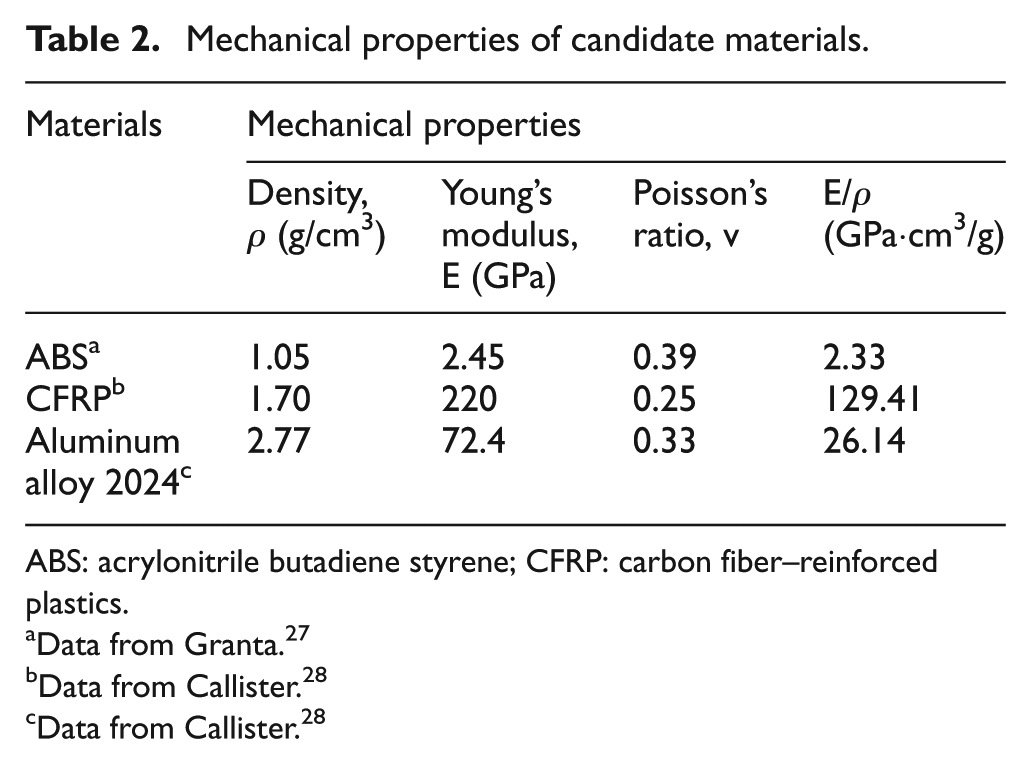
ABS: acrylonitrile butadiene styrene; CFRP: carbon fiber–reinforced plastics.
Data from Granta. 27
Data from Callister. 28
Data from Callister. 28
Results and discussions
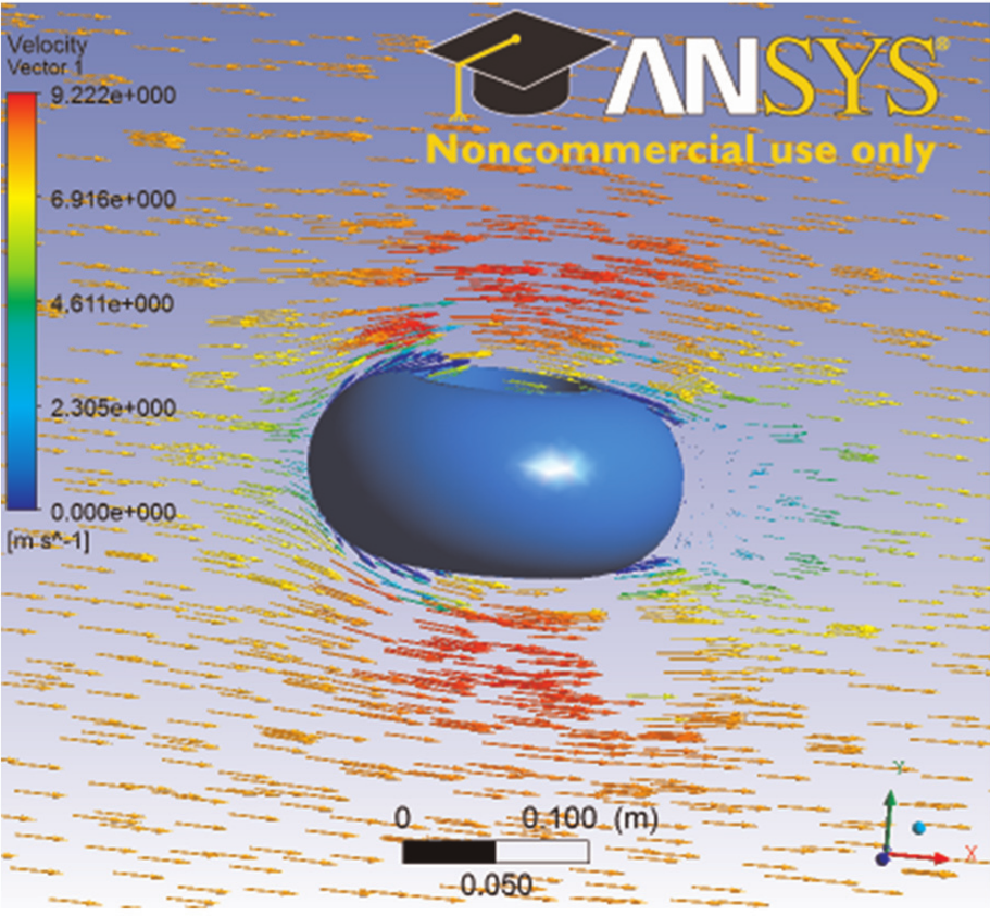
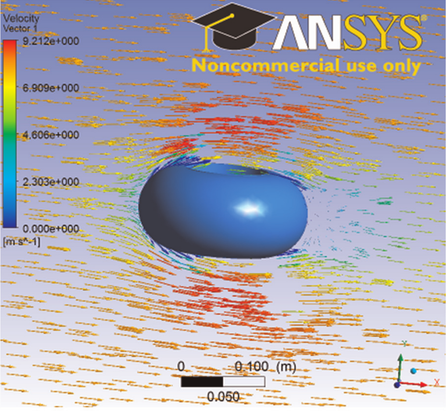
As expected, different aircraft with different structural design displays different flow distributions in a particular environment. The airflow velocity near the aircraft surface varies according to its physical location. The minimum value of air velocity along the membrane structure occurs at the largest radius point, as shown in Figure 5. And the distribution of airflow velocity is constantly changing with the time step. Slight changes can be observed from Figures 6–8. Meanwhile, the airflow pressure and the aeroelastic deformation produced by the airflow pressure have certain relationship with the outside air velocity, and at this point, the air pressure and the deformation both reach the maximum. The deformation produced by the elastic force at the largest radius point is shown in Figure 9. The maximum value of the curve represents the aeroelastic characteristic of the designed aircraft model.
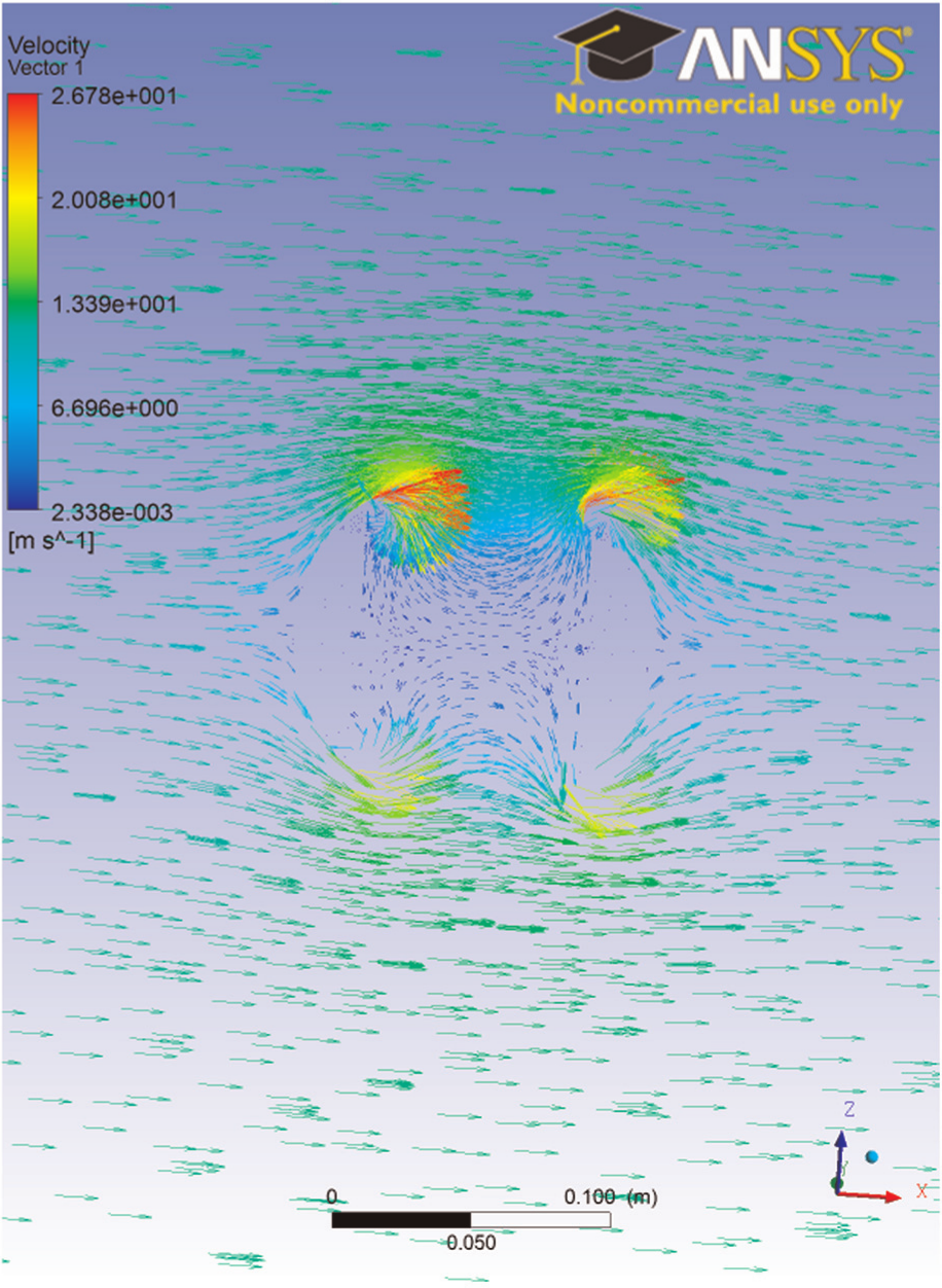
Typical airflow velocity distribution near the surface (based on the second run of orthogonal experiments).

Distribution of airflow velocity at 0.01 s calculation time.
Distribution of airflow velocity at 0.02 s calculation time.
Distribution of airflow velocity at 0.03 s calculation time.
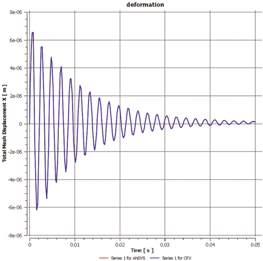
Typical deformation curve (based on the fifth run of orthogonal experiments).
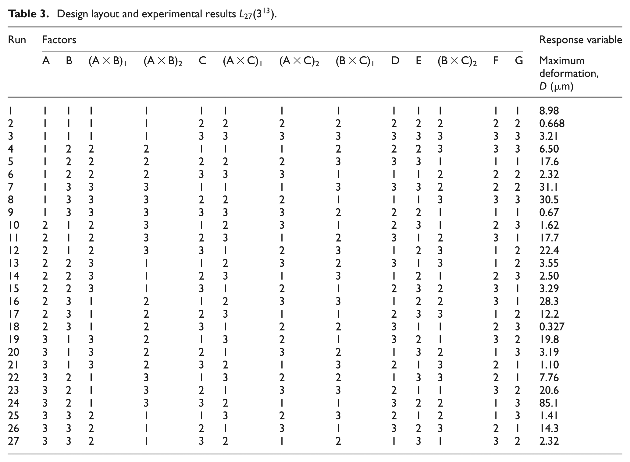
The orthogonal array has 27 runs of experiment (with a degree of freedom of 26). Seven columns have been assigned to the factors given in Table 1, and the remaining columns are used to study their interactional effects. The experimental results are shown in Table 3, with the main effects plotted in Figure 10.
Design layout and experimental results
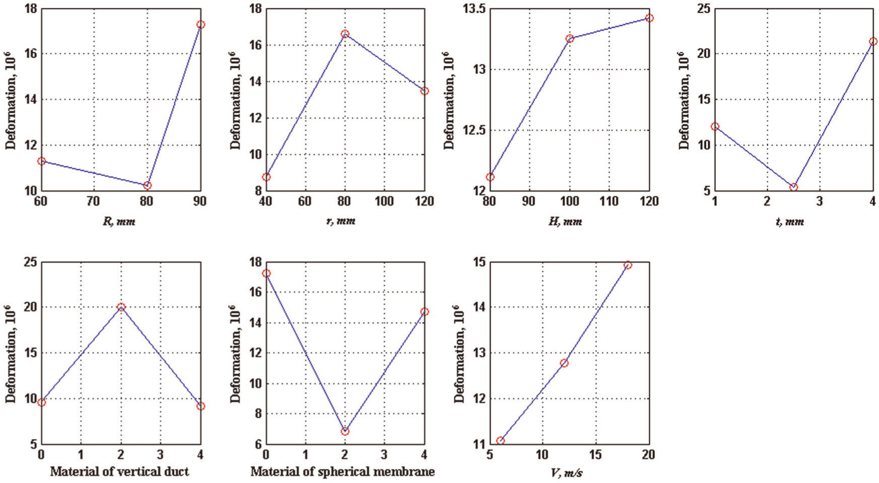
Main effects of factors on elastic deformation.
Since the main effects of factor C (height of vertical duct) and G (airflow velocity) manifested as the range values are relatively small, the two factors may be pulled together as the error factor to investigate significant factors. Table 4 shows the results of the analysis of variance (ANOVA) with deformation values.
ANOVA table.
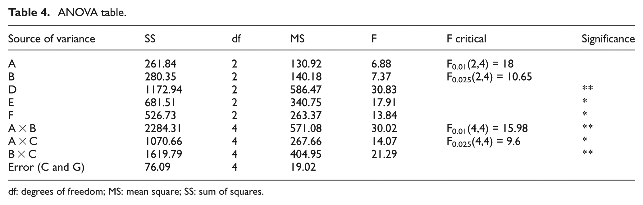
df: degrees of freedom; MS: mean square; SS: sum of squares.
The ANOVA is carried out at a significance level of 1% and 2.5%. Asterisks represent the statistical significance of the factor effects. For example, a factor with ** has a greater statistical significance than a factor with *, which, in turn, is more significant than factors with no *. It is clear from the ANOVA table that among the main effects, factor D (membrane’s thickness) has the most significant influence on the deformation results, while factor E (vertical duct’s material) and factor F (membrane’s material) are more significant than factor A (radius of spherical membrane) and factor B (radius of vertical duct). As for the two-factor interaction effects, the combination of factor A (radius of spherical membrane) and factor B (radius of vertical duct) as well as the combination of factor B (radius of vertical duct) and factor C (height of vertical duct) are more significant than the combination of factor A (radius of spherical membrane) and factor C (height of vertical duct).
The main effects plotted in Figure 10 have shown some interesting trends. For instance, the first level of factor A (radius of spherical membrane) is 60 mm with an average effect of 11.28, the second level is 80 mm with an average effect of 10.21 and the third level is 90 mm with an average effect of 17.29. Thus, when the radius of the spherical membrane changes from 60 to 90 mm, the deformation of aircraft aerodynamic shape tends to decrease first and then increase.
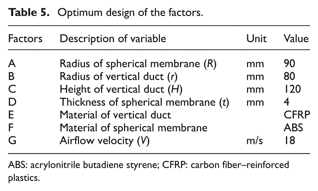
In addition, the optimum design or combination of structural parameters and material properties may be determined by comparing the average effects at each level for each factor (from Figure 10), which is A3B2C3D3E2F1G3 as shown in Table 5 for the designed aircraft.
Optimum design of the factors.
ABS: acrylonitrile butadiene styrene; CFRP: carbon fiber–reinforced plastics.
Experimental verification
According to the optimum design parameters from the orthogonal experiments and actual environmental constraints, the aircraft model was manufactured by 3D rapid prototyping. Figure 11 shows the assembly of drive motor, rotor blade and battery fixed inside the cylindrical vertical duct.
Aircraft model.
The experimental verification mainly involves measuring the aeroelastic deformation of the flexible membrane structure of the aircraft and providing comprehensive evaluation of its flight stability as well as performance produced by the aerodynamic shape, especially under an airflow disturbance. The experimental verification makes use of a wind tunnel testing system with stereo vision, which has been previously proposed. 29 It consists of strobe light, synchronous trigger binocular vision instrument, adjustable airflow generator, and multifunctional sensor as a closed-loop environment control system, which is shown in Figure 12. Deformation measurement is based on stereoscopic vision model, and stroboscopic imaging method is presented in Figure 13.
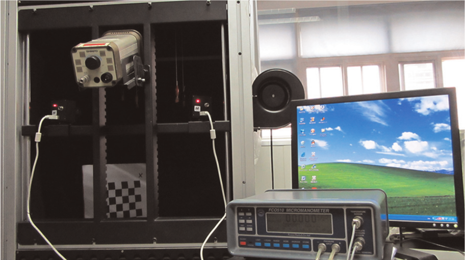
Wind tunnel testing system.
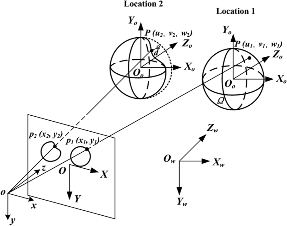
Stroboscopic imaging model.
Two locations of the object in motion are recorded using stroboscopic imaging method. In the model,
Using specific artificial texture printed on the aerodynamic shape of the aircraft, scale-invariant feature transform (SIFT) features can be extracted from the stroboscopic continuous images to reconstruct and represent the deformable membrane and calculate the aeroelastic deformation value. The test method has been detailed in Wang and Yu. 30 Combining the measurement results with the mathematical model established in Yu et al., 31 the antidisturbance mechanism of hovering flying model can be deduced. The full experimental results of the optimum design model will be reported and presented in a future article.
Conclusions
Flight stability analysis of an aircraft structure is an integral part of its design phase. In particular, such investigation is also important for MAV with a flexible aerodynamic shape intended for better flight performances. In this study, a hovering ducted-fan aircraft design model with spherical membrane structure was presented and its Reynolds number was determined. Modeled as the FSI involving the aircraft aerodynamic shape, the stability of the hovering MAV was investigated using finite element analysis (FEA) and the theory of motion of structure. Moreover, in order to optimize the flight performance and stability, OED for flexible deformation has been carried out with detailed analysis. The main findings of the investigation are as follows:
The thickness of the membrane and the material of the vertical duct are the two most significant factors influencing the results. Change in any of these factors will yield a significant variation in the response. However, the duct height and the airflow velocity seem to have relatively small effects on the results.
Factors causing an extreme value in the results have been identified, namely, thickness of membrane, vertical duct material, membrane material, radius of vertical duct and radius of membrane. For example, the elastic deformation results appear to have a minimum value when the membrane’s radius varies in the range between 60 and 90 mm. Similarly, a maximum value in the deformation occurs when the vertical duct’s radius changes from 40 to 120 mm.
The optimum combination of structural geometric parameters and material properties for aircraft’s flexible deformation was determined as A3B2C3D3E2F1G3. The combination of 90 mm membrane radius, 80 mm duct radius, 120 mm duct height, 4 mm membrane thickness with ABS membrane and CFRP vertical duct under 18 m/s airflow speed yields better flight stability.
Footnotes
Funding
This work was financially supported by Support Program of National Ministry of Education of China (No. 625010110), National Natural Science Foundation of China (No. 61179043), and Specialized Research Fund for the Doctoral Program (SRFDP) of Higher Education (No. 20070056085).