
Abstract
In the field of tactile surface probing, the contact point between the probing tip and the surface varies depending on the local surface slope. The measurement of high slopes as found in microstructures leads to deviations as the probing point no longer lies on the tip’s apex. A probing principle is investigated that applies a surface slope–dependent sensor rotation to reduce measurement deviation by shape superposition. For planning purposes and the determination of the benefit, a simulation of the probing process was performed. Different kinematic chains to rotate the sensor were investigated, and a stacking of two rotary axes was selected. To compensate systematic positioning deviation, a compensation field is applied, acquired by an in situ calibration method. As a basis for the test stand, a nanometer resolution coordinate measuring machine is used and is combined with a near-tactile micro- and nanosensor based on electrical interactions. The test stand has been completed in a preliminary configuration, and the first results are presented.
Introduction
For tactile surface measurements, it is common that the shape of the probing element overlays with the surface topography, and a morphological filtering is performed. 1 Depending on the local surface slope and the tip’s form, the contact point between them varies. In the case of three-dimensional (3D) coordinate measurement machines and their ball probes, the contact point can be detected by 3D force sensors, but restrictions on the tip size apply. 2 Tactile scanning systems like profilometers or atomic force microscopes (AFMs) as used in micro- and nanometrology feature smaller tips and allow a higher lateral resolution but instead have a fixed probing force direction, complicating the probing point reconstruction.3,4 Yet without the knowledge of the actual probing point, large deviations can occur, especially on steep surfaces as the probing point moves from the expected reference contact point. The resulting deviation can be calculatively compensated to a certain degree, 5 but when the probing point leaves the spherical front, the recorded trace can no longer be unambiguously reconstructed. The applied tactile tips feature a small spherical apex at the front of a conical or pyramidal base, limited by the mechanical stability. For profilometers, the angle of the base is usually up to 90° with apex radii up to 2 µm. 6 Figure 1(a) shows the result when the front of the sensor tip is assumed as a probing point for surface reconstruction. When the contact point moves to the flank of the tip, the deviation increases significantly. This especially happens during the measurement of workpieces with high slopes, for example, cutting tools, freeform lenses, or high aspect ratio nano- or microstructures like microlens arrays. For example, in the case of microelectromechanical systems surface, slopes up to 90° are present. This problem limits the application field for tactile surface probing to surfaces with limited curvature.7,8
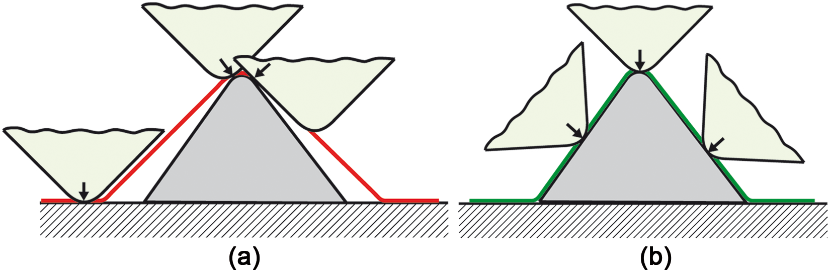
(a) No compensation: reconstructed surface deviates from real surface (arrows indicate the probing vector). (b) With compensation: deviation from real surface is reduced (arrows indicate the probing vector).
To counteract this problem, a probing principle is investigated that uses a dynamic surface slope–dependent tip rotation to keep an orthogonal orientation to the surface during the measurement. The resulting deviation reduction and the rotated tip are displayed in Figure 1(b). Research has shown that the deviation on steep flanks can be reduced using angled probes but leading to higher measurement deviation on the rest of the sample. 9 With repeated measurements under different angles, segments of single scans can be joined by applying sensor data fusion to acquire the whole surface. Yet this leads to a high measurement time and additional contributions to the measurement uncertainty.10,11 Instead, by using the planned sensor tilting during measurement, both disadvantages are avoided. To reach this goal, research has been carried out. 12 In the first step, the contact process between the surface and a tilted tip is implemented into a simulation environment as the basis for all tests. The environment allows for the examination of different strategies and algorithms to allocate a tilt angle of the tip to a surface point. The strategies are later included into the control system of the test stand. With the results from the simulations, different possible kinematic chains can be better compared concerning their effectiveness in order to realize a tilting system. In the end, a rotation unit is selected and a test stand prototype is realized.
Simulation environment
The working principle of the simulator is based on collision checking between a geometrical model of the tip and the discretized surface. A simplified 2D model is selected to reduce the complexity yet keeping the informative value for line scans. The tip is modeled with geometrical functions, following the standard ISO 3274, 6 as a spherical tip with the radius r around the center M and two lines, enclosing the apex angle alpha (Figure 2(a)). The height h and the corner points Fl,o, Fl,u, Fr,o and Fr,u of the tip complete the description.
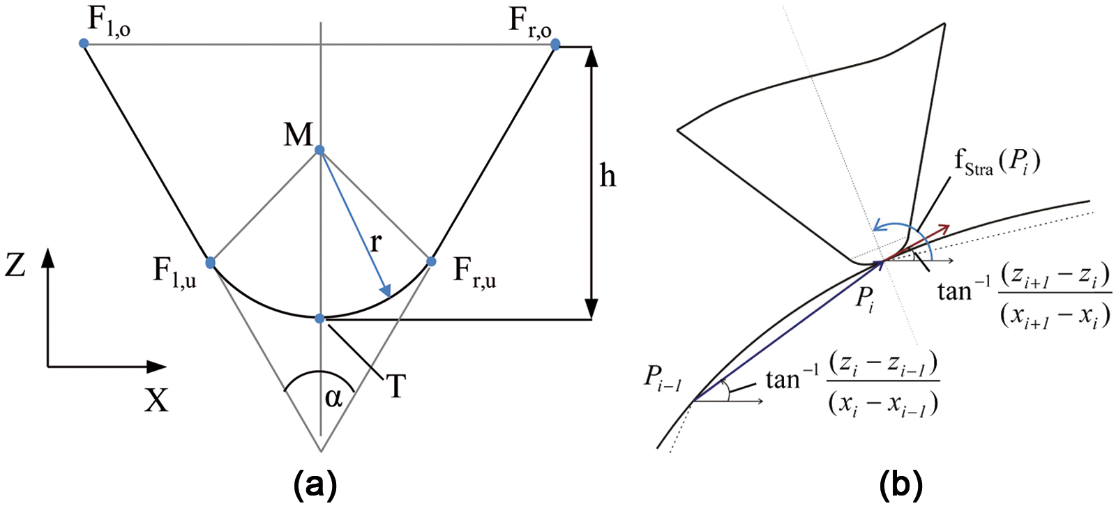
(a) Geometrical model of the tip, conical, and spherical part and (b) angle determination with discrete surface points.
The surface profile is integrated as a discretized point cloud, similar to a real measurement process acquiring the surface pointwise. The function P(x, z = f(x)) gives the profile height at the coordinate x. The simulators’ core logic is based on a collision check between the rotated tip and the surface. It detects a possible overlap of the two models and shifts the tip upward until the conflict is resolved and a single contact point remains. By repeating this procedure and performing a rotation movement as calculated by the strategies, the surface is acquired.
Sensor tilting strategies
To determine a suitable probing angle, methods and algorithms are required and are referred to as a strategy. Several approaches are thinkable and can be categorized in knowledge-based, analyzing, predicting strategies or a mixture of the aforementioned. They operate as a control logic during the measurement to calculate the optimal probing angle of a specific surface point. A first class, the knowledge-based strategies, uses previous knowledge of the surface profile from an ideal model, for example, a computer-aided design (CAD) file. In the simplest case, the tangential for each surface point P(x, z) can be calculated with Pi(x, z) being the point number i to be measured and with fStra(Pi) as the calculated probing angle. The angle, displayed in Figure 2(b), results in
A similar class, the analyzing strategies, creates a base profile with the measurement system itself in a first pass. In a second pass, tilting can be applied. This approach does not require previous knowledge and can be applied with unknown profiles. The algorithms are similar to a knowledge-based approach. A third class, predicting strategies, calculates the most suited tilt angle from the extrapolation of the already acquired surface points during the measurement. Generally, the measurement is started without rotation, and the surface points are recorded, written to a buffer. The next points are extrapolated based on these values and the applied algorithm. With the estimation of the succeeding profile, the optimal tilt angle is calculated, the tip is rotated and the next measurement points are recorded. For this class, several extrapolation algorithms were selected and compared. 13 For example, a linear method, a cubic spline method, a Newton method, a Lagrange method or an Aitken–Neville method was implemented.
Evaluation of the strategies
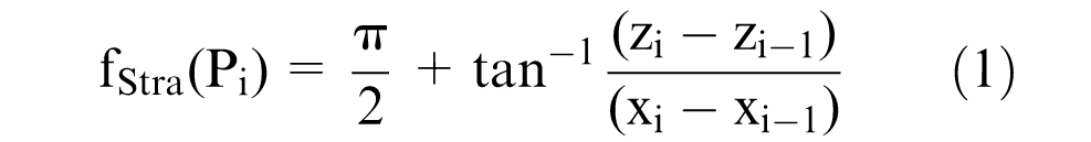
With the completed simulation environment, the effectiveness of the strategies and the achievable deviation reduction were compared with different tips and surfaces. Relevant evaluation criteria were, for example, the measurement deviation, the calculated tilt angle (ideal/limited) or the tilt velocity and acceleration. Different sample surfaces were created based on simple geometrical elements to cover usual practical cases. One sample consists of a sphere segment with the radius of 0.5 mm starting at a flat part (Figure 3). Its center is embedded and lies 0.08 mm below the zero layer. This surface, found, for example, on lenses, shows a continuous change of slope.
Linear prediction strategy compared to a regular scan: half sphere, 1 mm in diameter.
Figure 3 displays the general behavior of predicting strategies compared to a regular scan. The simulated experiment used a tip with a tip apex radius of 10 µm, an opening angle of 60°, a maximal rotation angle of 45° and a maximum rotation speed of 1°/s. At the beginning of the sphere’s edge, a flank collision with the sphere occurs and the resulting deviation suddenly rises. With the linear extrapolated surface slope changing, a rotation is triggered. The deviation is reduced, limited by the configured rotation speed and the maximum tilt angle. A necessary tilt angle of over 70° to the left is calculated starting from no rotation, and the actual angle, restricted by the hardware configuration, rises until it hits its maximum and then follows the calculated angle. During the scan, the flank collision is resolved by the rotation until the contact point wanders into the spherical part and in its apex. Now, the deviation by tip geometry is eliminated. With the ongoing scan, the tip turns to the right until it hits the maximum possible angle of −45°. Now compared to the first transition from the flat to the sphere, a far lower deviation can be reached at the second transition as the tip is now better aligned. With the tip being at an angle of −45°, a slight flank collision with the sphere appears near position 1.2 mm, but no collision with the flat part occurs. With an analyzing strategy, this behavior could also be reached at the first transition. In the rest of the scan, a slight deviation is still present until the actual angle meets the calculated angle. Of course, with a faster simulated rotation speed, the deviation would be reduced, yet this mechanical restriction is imposed to investigate different kinematic solutions.
A second structure features an abrupt transition of 18° between two constant slopes (Figure 4). This configuration can be part of, for example, a triangular profile or represent, with a higher angle, a steep wall found in the microelectromechanical systems. The ramp profile focuses on the ability to adapt to the transition between fixed slopes. The slope leads to a constant deviation contribution for a nontilted case without computational probing point compensation. In comparison, predicting strategies completely reduce the deviation, and furthermore, analyzing strategies initiate the rotation before the slope change occurs. For the latter case, the maximum deviation is reduced from 0.51 µm without tilt, mainly depending on the tip geometry, to 0.13 µm with an analyzing strategy. Generally, all tested strategies offer a significant deviation reduction and increase the detectable surface slope with a tilting system compared to no countermeasures at all. Differences between the performances of the strategies appear for changing system parameters like tip geometry, rotation angle limits and especially higher rotation speeds. Finer differences can be found in the generated angular acceleration, the earliness to react on a slope change and the swing up tendency.
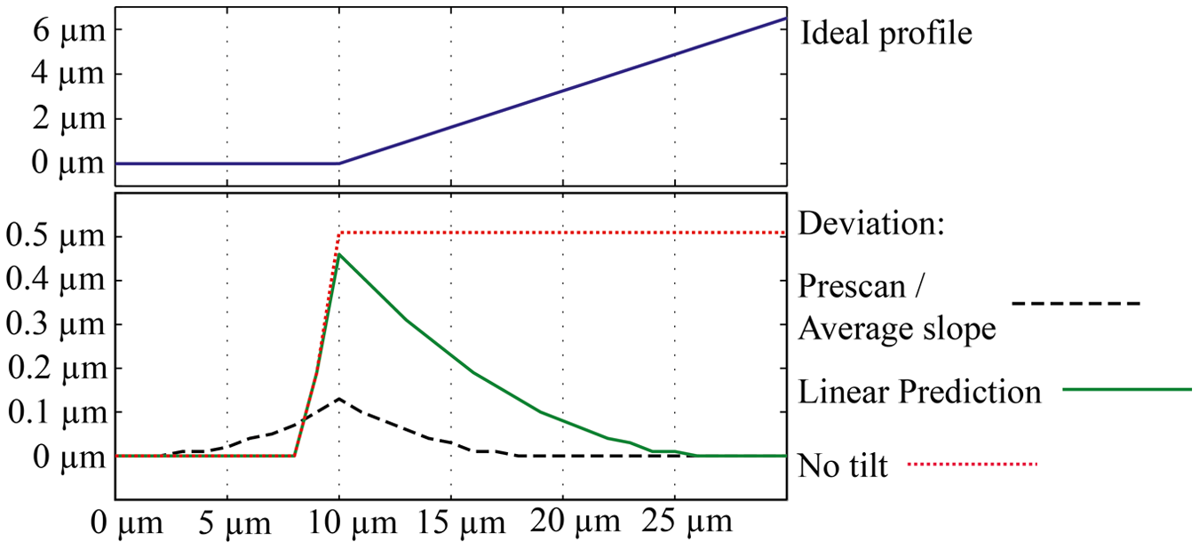
Comparison of strategies: ramp profile with a slope of 18°.
Hardware realization
After demonstration of the feasibility of the principle and the achievable deviation reduction with the simulation, the hardware design can be completed. To transfer the tilting process to a real environment, a controlled precision servo system is necessary to perform the rotation around the tip’s working point. A high-positioning accuracy with low guidance deviation is required, elsewise, the measurement deviation would instead be increased by leaving the assumed scan trace. Yet in practice, all kinematic solutions are inflicted with systematic and nonsystematic error motions. In the case of rotation axes, those are axial and radial error motions as well as tilt along the center axis due to guidance imperfections. Further contributing factors to the positioning quality are angular resolution and repeatability. Several kinematic chains were investigated concerning their achievable positioning accuracy, the deviation during operation, achievable rotation angle, rotation speed, overall size and their costs. The basis of the planned test bed is a laser interferometer–controlled nanopositioning and measuring machine type SIOS NMM-1 with an axis resolution of 0.1 nm in three linear axes. The movement range covers 25 mm in the lateral directions (x, y) and 5 mm in the height (z) with a positioning uncertainty of 10 nm.14,15 As the sensor is fixed above the workpiece and the workpiece itself is moved, all planned solutions focus on a moved sensor installed top-down above the translatory system. The alternative option to rotate the workpiece was omitted mainly due to size restraints, higher moving mass and worse transferability later on to other systems. Three of the most relevant investigated approaches shall be described briefly in the following.
The first investigated solution consists of a single rotation stage, installed with its axis perpendicular to the height axis of the NMM-1. The sensor is mounted in radial direction and moves on a circular path during operation. To achieve a rotation around the working point, a lateral compensation movement by the translatory axes of the NMM-1 is required. Additionally, a short distance between the center of rotation and the sensor tip is desired to reduce the effective deviation caused by angular error motions. A market overview showed that stages with low guidance deviation, for example, nonsystematic radial deviation below 1 µm and tilt below 3 arcsec and an additional error mapping usually have diameters above 100 mm. Miniature stages with piezoelectric drives would allow for a less off-axis operation, but usually no full calibration data are available, and the given values are higher in comparison, resulting in a larger overall deviation. Calculations for a specific rotation stage led, for example, to a positioning window for the sensor tip with a width of ±1 µm in the measurement direction. The precondition was a full compensation of all systematic contributions and a distance between the axis center and the tip of 70 mm. A downturn of this solution is the restriction of the available rotation angle and the limit to one degree of rotation. With the nanopositioning stage having to compensate the circular movement, a translatory scanning range of only 5 mm would remain for a rotation angle ranging from −10° to +10°.
A second solution applies a parallel kinematic offering six degrees of freedom without the need for a compensation movement. Parallel kinematics with an overall size to fit into the NMM-1 usually feature piezoactors as drives and allow for nanometer step size. For the estimation of the achievable positioning accuracy, the datasheet values for translatory and rotatory errors were applied. The positioning window of the sensor’s front, mounted 25 mm above the top, was calculated to be ±230 nm. To further evaluate this solution, a parallel kinematic has been examined in our laboratory, and a short test confirmed the dimension of the datasheet values. A positive aspect of parallel kinematics is the free choice of the sensor rotation point, facilitating the precision alignment compared to other solutions. Yet this solution was discarded due to its comparatively high costs and the limited angular range of, for example, ±10°.
A further solution applies two stacked rotary axes. The axis of the first rotation stage is oriented parallel to the height axis of the NMM-1. Below the axis is mounted a second rotary stage under an angle of 45°. Fixed to the second stage is the sensor, again angled with 45°. In this setup, the centers of both axes align with the working point of the sensor, apart from deviations from the assembling.
The second axis alters the angle of the sensor, which equivalents to a rotation around the x- and y-axes of the NMM-1’s Cartesian coordinate system. With the additional movement of the first rotation stage, the sensor can be adjusted to match any necessary angle around the x- and y-axes from −45° to 45°. Figure 5 displays the applied principle.
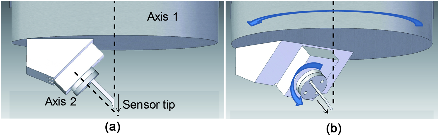
(a) Sensor at zero rotation and (b) sensor rotated by 45°.
This solution can only be applied with point sensors because an additional rotation around the sensor’s center axis is induced. The benefit compared to the single rotation axis is the in-axis alignment of the sensor. The importance of angular resolution is reduced as it no longer leads to a significant lateral deviation in the setup. The only remaining deviation factors are the radial and axial deviations as well as tilt. Additionally, the full operating range of the NMM-1 can be utilized as no compensation movement is necessary. Positioning window estimations result in a maximum deviation of ±1.5 µm, but no full datasheet exists for the smaller stage. This option is favored over the others as it has the fewest restrictions and can be switched to the first solution with the same hardware. As a primary axis, a direct-driven precision rotary stage with 100 mm in diameter was chosen with a nonsystematic tilt error motion of below 3 arcsec and a radial nonsystematic error motion of below 1 µm. As a second axis, a piezodriven miniature stage with a diameter of 30 mm and a resolution of 0.0072 arcsec was chosen, based on a ceramic bearing.
Realization of the test stand
Choice of the applied sensor
The simulation focused on a tactile point sensor like a profilometer or AFM. To accelerate the realization of the prototype, a near-tactile probe was selected, conforming to the simulated deviation mechanics.16–18 The sensor’s working principle is derived from scanning tunneling microscopy (STM). By applying a voltage of millivolts between a conductive tip and workpiece, a current of nanoamperes can be measured, and it increases exponentially with the reduction of the gap between the tip and workpiece. As opposed to regular STMs, no sharp wire tips are used, but larger scaled spherical probing tips are used. The current, flowing through the gap between the tip and workpiece on a grounding plate, is detected with a highly sensitive sensor circuit. The sensor can be operated in a scanning mode as well as a touch trigger mode, similar to tactile coordinate measurement machines. It allows for deliberatively shaped tips, ranging from spheres to conical shapes or needles without having to respect mechanical restrictions. 18 Because of its ease of system integration and the ability to operate like a tactile system, this system was selected. For the test stand prototype, two tip shapes were chosen. The first scenario uses a hard metal sphere tip with 0.3 mm in diameter equivalent to a tactile probe with a large apex radius, apart from flank collisions. When a probing point at the front of the tip is assumed for reconstruction, the system behaves like a tactile version, and the deviation can clearly be shown. As the electrical system with a spherical probing sphere does not necessarily require the rotation, a simple comparison between a rotated case and a nonrotated case is possible. Another advantage of the spherical probe is the later-on needed calibration of the rotation system, described in section “Calibration field and application of scan logic.” The second scenario features a sharp metal needle, with a smaller tip angle than a classical profilometer could operate with. This case represents an ideal tip without probing point deviation and delivers measurement data for a comparison.
Calibration artifact
To calibrate the rotation system and to offer test structures for demonstrating the effect of the sensor rotation, a calibration artifact is necessary. The aim is to locate the sensor probing point at each angle in relation to the workpiece coordinate system. With this knowledge, theoretically, all systematic deviation components from the rotation system and also imperfect alignment can be compensated. As a reference structure and origin of the workpiece coordinate system, a precision sphere grade G5 with a nominal diameter of 4 mm is used. A calibration was performed in our laboratory with a Werth Videocheck UA 400 and a microtactile probe type Werth Fiber Probe 3D, resulting in a diameter of 3.9994 mm ± 2.96 µm. When the spherical sensor tip is used to measure the upper hemisphere of the calibration artifact, ideally with 25 distributed points, 19 a superposition of both shapes occurs. This results in a sphere with the radius of the calibration sphere plus the radius of the probing element. Its center can be determined with a sphere-fitting algorithm, for example, a Gaussian type. 18 The center of the probing tip hence results from the recorded probing points and their respective angle to the calibration sphere’s center.
Beneath being the calibration artifact for the probing point determination, the sphere can also be used as a measurement subject for the rotation principle. It represents a continuous change of slope from −180° to +180°. As another measurement subject, three angled planes with rounded transitions are chosen. The angle between two neighboring flats is each 30°. Additionally, all flats are angled in the perpendicular direction too. The test subject is part of a cutting insert that was shortened by wire erosion to fit into the working volume. The shape of cutting inserts is of high importance to the cutting process and is therefore a frequent measurement subject. 20 Figure 6(a) shows the resulting calibration setup and its integration into the test stand (Figure 6(b)).
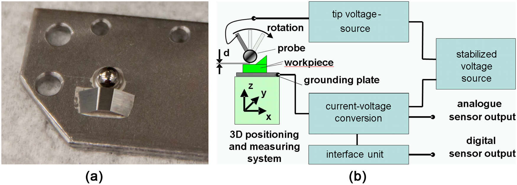
(a) Calibration artifact on a carrier plate: calibration sphere and angled flats of a cutting insert. (b) Integration diagram of the sensor into the test bed.
Calibration field and application of scan logic
With the described artifact, the position of the rotated sensor can be acquired, compensating the systems systematic positioning deviations. The correction vectors from workpiece origin to the center of the probing sphere are stored in a calibration field, accessed by the machine control during the scanning operation. Depending on the number of recorded angular positions, the field can be interpolated for all intermediate values or the rotation stage can be operated with only the calibrated angles.
The measurement process assisted by the calibration field is performed in the following steps. First, the sensor is usually aligned perpendicular to the workpiece carrier, and the sensor approaches the surface at the starting point of the scan. A number of points are recorded to have a sufficient calculative base for the surface angle determination. After enough values are stored in the machine coordinate system, the surface points are transferred into the workpiece coordinate system with the current compensation vector as the tip’s absolute coordinates change depending on the angle. A further correction vector directs to the contact point on the tip as the calibration field references to the tip’s center coordinates. For a nontilted case, a correction vector to the lower pole of the tip is assumed; for the rotated case, a vector in tilt direction is assumed. After the surface points are stored in the workpiece coordinate system, the algorithms of the chosen strategy are applied, calculating the surface angle and the next suitable tilt angle. If the requested change of angle is above a selected threshold, the probe gets disconnected from the surface and the rotation is performed. In a fully dynamic scan to be realized later, a surface disconnection is not necessary. The new probe center point is loaded from the calibration field, and the sensor is brought over the last recorded surface point. Afterward, the measurement continues until all required points are recorded. An optional fine calibration can be applied, acquiring a more recent calibration with the sphere just after the rotation has been performed. The fine correction results in a higher accuracy of the system as time variant components of the field are reduced, but of course, this leads to a higher measurement time.
Preliminary tests
To implement all necessary algorithms and sequences in the target system before the setup and the control system for the stacked axes are completed, the test stand was realized with a preliminary rotation unit. Temporarily, a simple manual rotation axis with a diameter of 25 mm was installed, carrying the electrical sensor (Figure 7(a)). A reproducible rotation with this manual stage is of course not comparable with the planned precision stages. Yet it is sufficient to perform a functional test of all algorithms, strategies and calibration field. Additionally, the described fine calibration was tested. As the manual axis’ reproducibility is insufficient, this method is obligatory. All program codes were realized with MATLAB, as the NMM-1 can be controlled with this software environment. Figure 7(b) shows all acquired data merged in the workpiece coordinate system, with the center of the sphere as the origin. In front of the sphere is a line trace of the cutting insert over all three tilted planes.

(a) Preliminary axis setup with a 0.3-mm sensor tip, fixed in an electrically isolated adapter. (b) Display of the compensation field in the workpiece coordinate system.
Above the hemisphere are the centers of the probe from the calibration field tip at different angles, displayed with a sphere of 0.3 mm in diameter. In the current case, seven angle positions from −30° to 30° were acquired. Due to the used kinematic, the center points describe a circular path. With this preliminary prototype, a rotation angle of ±30° is possible, limiting the lateral scan range on x of the NMM-1 to at about 5 mm.
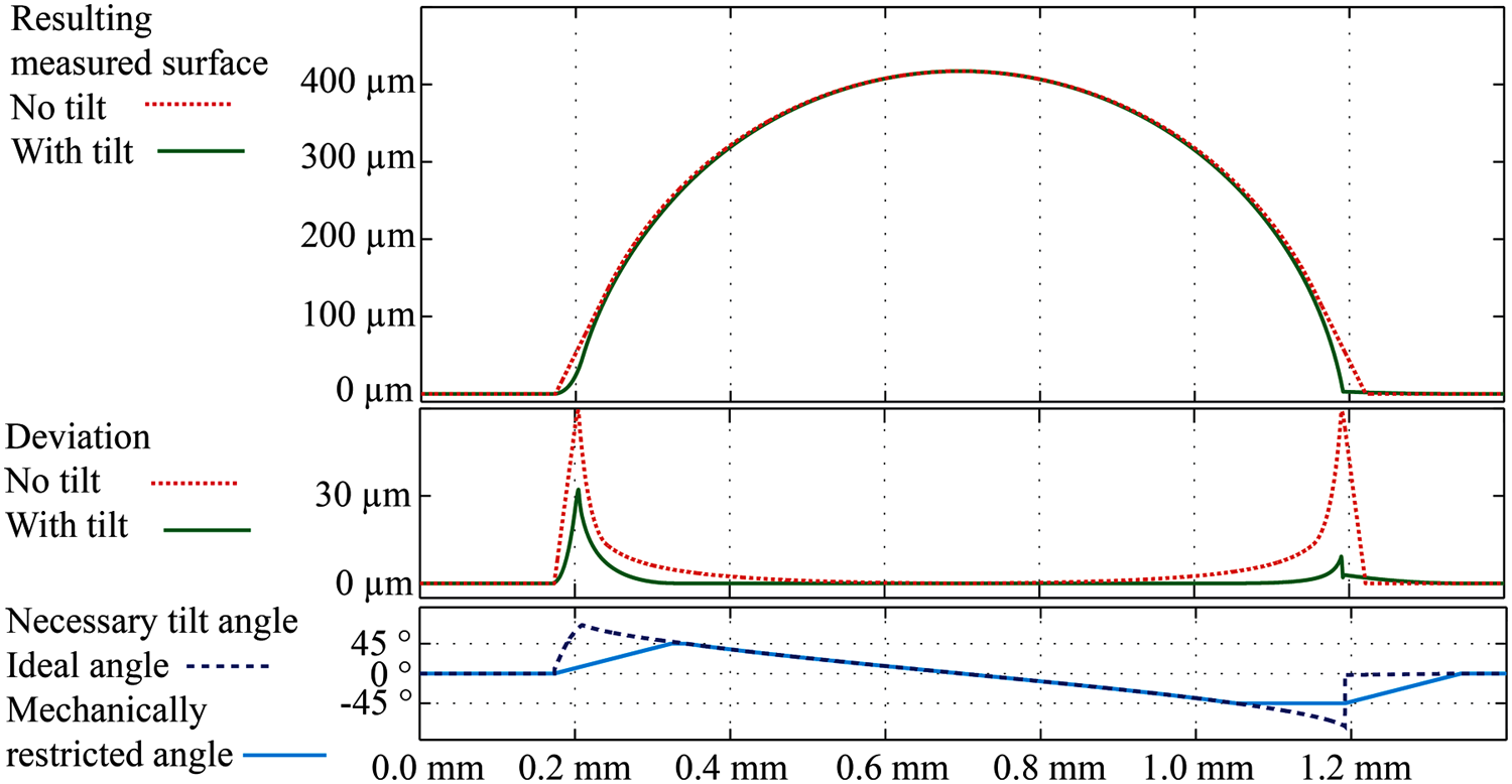
A first measurement on the angled flats with the described logic is shown in Figure 8, splitted into the left flank and the right flank. The upper curve represents a scan without tilt, assuming a probing point at the lowest part of the tip, as a profilometer would result to. The lower curve uses sensor rotation with a probing point in rotation direction and an angular step width of 10°. It is visible that both ways result in the same values in the flat top, as expected. In the sloped parts, on the other hand, a difference can be seen as the rotated tip is more capable in keeping its assumed probing point. This is clearly observable in the beginning of Figure 8(a) when the rotated tip starts at 0° and then after some surface points switches to 30°, and the deviation is instantaneously reduced. Other effects of interest are discontinuities in the rotated scan. They are caused by the sudden change of the assumed probing vector when the axis is turned with a 10° increment. For the demonstrated test case, the measurement deviation was reduced by up to 18 µm. These results are, of course, from an early prototype stage but still show the applicability and the achievable gain by the rotation principle. With the integration of the stacked axes into the test bed, a deeper investigation of the principle in practice will follow. Also the range of test surfaces will be extended covering reference structures like a microcontour artifact.
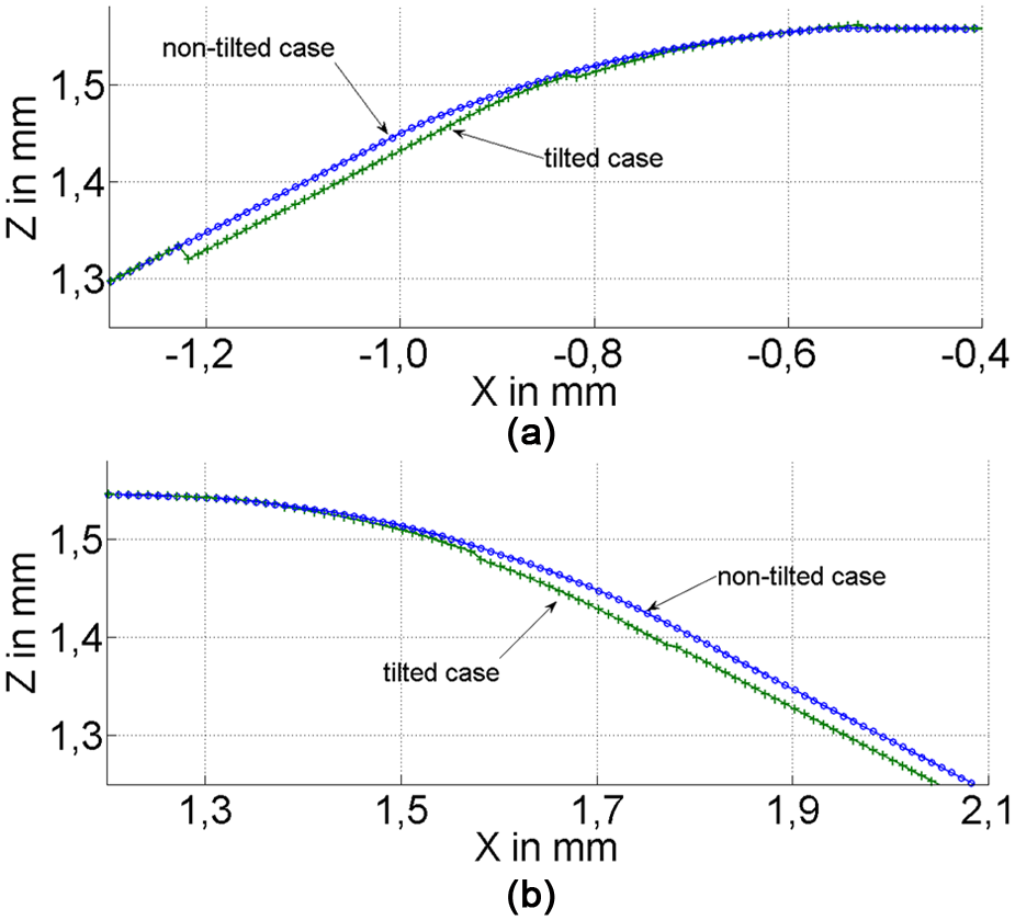
(a) Angled flat: left transition and (b) angled flat: right transition.
Summary
A probing principle based on dynamic sensor tilting is investigated with a rotation around the sensor’s working point. Based on a simulation environment, the measurement deviation mechanics are modeled and the effectiveness of the rotation principle is evaluated. Strategies and algorithms were developed to allocate a rotation angle to a surface point during the measurement. Afterward, simulations were performed to evaluate the strategies on different real-life sample surfaces. The results demonstrate the improvement by sensor tilting, reducing measurement deviation and increasing the usable surface slope. The simulation results are used in the selection of a kinematic chain to realize the sensor tilting. Different alternatives ranging from a single rotary axis to parallel kinematics and to stacked rotary axes are investigated with the aim to achieve a positioning deviation lower than the deviation reduction by sensor tilting. As a result, two stacked rotary axes as a kinematic for the sensor rotation were chosen. They will be installed in the test bed consisting of a laser interferometer–controlled nanopositioning and measuring machine type SIOS NMM-1 with an axis resolution of 0.1 nm. As sensor for the test stand, a near-tactile principle based on electrical near-field interaction is used allowing the application of deliberately shaped tips. To reduce the remaining systematic positioning deviation of the rotation stage, an in situ calibration strategy is realized. With a calibration artifact, a calibration field is recorded storing compensation vectors for each rotation angle. After the calibration and a test artifact were manufactured, the test bed has been realized and the algorithms and sequences are tested with a preliminary simplified kinematic. The reduction of the measurement deviation by applied sensor rotation was shown even with the temporary setup. The demonstrated logic and methods will be transferred to the two stacked rotary axes after their upcoming integration in the test bed.
Footnotes
Acknowledgements
This article is based on the research project “Ultra-accurate acquisition of highly curved surfaces by slope-dependent dynamic sensor tracking with rotatory flexure hinges.” The authors would like to thank Frederik Berger for his support with the setup and the test of the manual rotation stage.
Funding
This study was supported by the German Research Foundation (Deutsche Forschungsgemeinschaft, DFG).