
Abstract
Dimensioning and tolerancing standards originated about 75 years ago in the form of various national and company standards that governed engineering draughting and documentation practices. They served the purpose of communicating to manufacturers what geometric variations designers could tolerate in a product without compromising the product’s intended function. These standards have evolved over time and are by now well entrenched in the engineering profession throughout the world. For several initial decades, this evolution was driven primarily by codification of best engineering practices without the benefit of any systematic scientific treatment. This trend encountered a major hurdle in early 1980s when the emergence of computer-aided design and manufacturing systems forced a drastic reexamination of these standards with a greater emphasis on mathematical formalism. Since then, scientific principles to explain past practices and to guide future evolution have emerged, and the role of science has now become more prominent in the development of these standards. This article describes some of the key scientific research results that have already had an impact, and the future scientific trends that are likely to have an influence, on these evolving standards.
Introduction
In 1991, the Pennsylvania State University in the United States hosted a College International pour la Recherche en Productique (CIRP) Computer-Aided Tolerancing (CAT) Working Seminar. By some current count, it was the second of a series of what has come to be called the CIRP CAT Conferences (the first was a gathering on this topic at Jerusalem, Israel, in 1989). The Penn State “working seminar” was a timely event because several academic and industrial researchers had started working together to attack an important industrial problem using the computational power unleashed by the information age.1–4 The author was fortunate to be present at that workshop and spoke about how “a geometer grapples with tolerancing standards.” 5 That workshop, and other similar events organized around that time, launched a series of initiatives that resulted in the creation of the American Society of Mechanical Engineers (ASME) Y14.5.1 subcommittee and the International Organization for Standardization (ISO) Technical Committee 213, both dealing with tolerancing standards. And they spurred one of the most creative research activities in mechanical and computational sciences, as chronicled in the proceedings of the 12th CIRP CAT Conferences and other similar conferences and research journals.
Looking back at the article 5 written 22 years ago, two of its observations strike us as most consequential. The first was a call for mathematically sound definitions of the semantics of the standardized tolerancing language because the lack of such a scientific basis was hampering the development of provably correct algorithms for CAT. The second was a tentative mention of “computational metrology” to refer to a set of computational techniques that were emerging to cope with processing large amounts of measured data coming out of coordinate measuring machines. It was not clear at that time if these were merely naïve observations that would be promptly forgotten or important topics that would be pursued with vigor. In fact, one prominent academic at the conference scoffed at the very idea of referring to tolerancing standards as defining a “language with syntax and semantics.”
It is now heartening to reflect on the developments over the past two decades and see that both these observations have come to play an important role in the evolution of dimensioning and tolerancing standards. This article describes some of the scientific developments first (in sections “Congruence theorems” through “Computational coordinate metrology”) and their impact on the evolution of dimensioning and tolerancing standards next (in sections “Size tolerancing” through “Geometric characteristics and tolerancing”). Along the way, it will show how these scientific foundations have helped rationalize the past and current industrial practices, and how they are paving the way for important new avenues. Above all, the author hopes to communicate the excitement of one who has pursued geometric studies for fun as well as profit.
Congruence theorems
Congruence theorems dating back to Euclid provide an easy and powerful introduction to the notion of dimensioning (and parameterizing) geometric objects. To illustrate, let us start with the simple task of dimensioning and parameterizing triangles. Figure 1 shows some successful attempts. It seems intuitively obvious that all these three schemes are valid ways to parameterize triangles, and we get valid dimensions when numerical values are assigned to the distances and angles indicated by arrows.
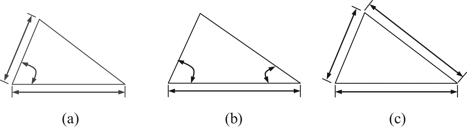
Examples of dimensioning and parameterizing schemes for triangles: (a) side-angle-side theorem, (b) angle-side-angle theorem, and (c) side-side-side theorem.
We can provide a formal theoretical basis for our intuitive belief by associating each example in Figure 1 with a famous triangle congruence theorem from Euclid’s elements: 6 Figure 1(a) with the side-angle-side theorem (Book I, Proposition 4), Figure 1(b) with the angle-side-angle theorem (Book I, Proposition 26), and Figure 1(c) with the side-side-side theorem (Book I, Proposition 8).
The geometric notion of congruence is closely related to the practical engineering notion of interchangeability of parts, as they both belong to an equivalence class. More formally, they satisfy the following three axioms:
Reflexivity. A is congruent to (or, interchangeable with) A.
Symmetry. If A is congruent to (or, interchangeable with) B, then B is congruent to (or, interchangeable with) A.
Transitivity. If A is congruent to (or, interchangeable with) B and B is congruent to (or, interchangeable with) C, then A is congruent to (or, interchangeable with) C.
In fact, an entire formal theory of dimensioning can be built using congruence theorems.7,8
The taxonomy of such a modern theory of dimensioning is shown in Figure 2. At the leaf nodes of the modern taxonomy of dimensioning, we see intrinsic dimensions. At the intermediate nodes, we see relational dimensions. The hierarchy can be built with as many levels as the product demands. Complex products may have more levels of hierarchy than simpler ones.
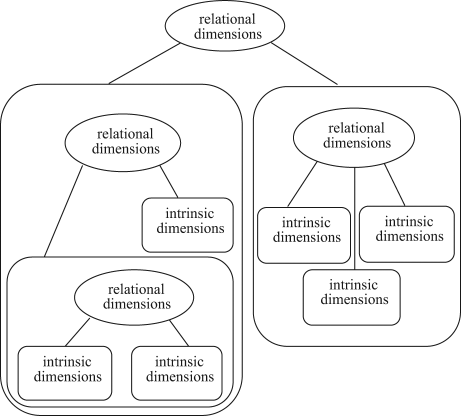
A modern taxonomy of dimensioning.
Congruence theorems formalize the dimensioning scheme at each level of the dimensional taxonomy. In section “Classification of quadrics,” we will see how this is accomplished for some of the commonly used intrinsic dimensions of surface features trimmed from quadric surfaces. Then, in section “Classification of continuous symmetry,” we will repeat the exercise for relational dimensions. As we lay the scientific foundation for these dimensioning schemes, it is useful to look ahead to section “Geometric characteristics and tolerancing,” where tolerancing standards have adopted a similar hierarchy for “individual features” and “related features” invoking the notion of datums. This point will be emphasized again in section “Geometric characteristics and tolerancing.”
Classification of quadrics
Most commonly used surfaces in engineering belong to second-degree surfaces called quadrics. These are defined by a set of points with x, y, and z coordinates as in
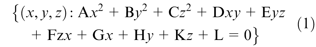
for real coefficients A, B, C, D, E, F, G, H, K, and L, where at least one of A, B, and C is nonzero. A well-known quadric classification theorem 9 states that any surface of second-degree governed by an equation of the form (1) can be moved by purely rigid motion in space, so that its transformed equation can assume one and only one of 17 canonical forms. Of these 17 canonical forms, only 12 can have solutions for real values of x, y, and z, and they are shown in Table 1.
Classification of real quadrics.
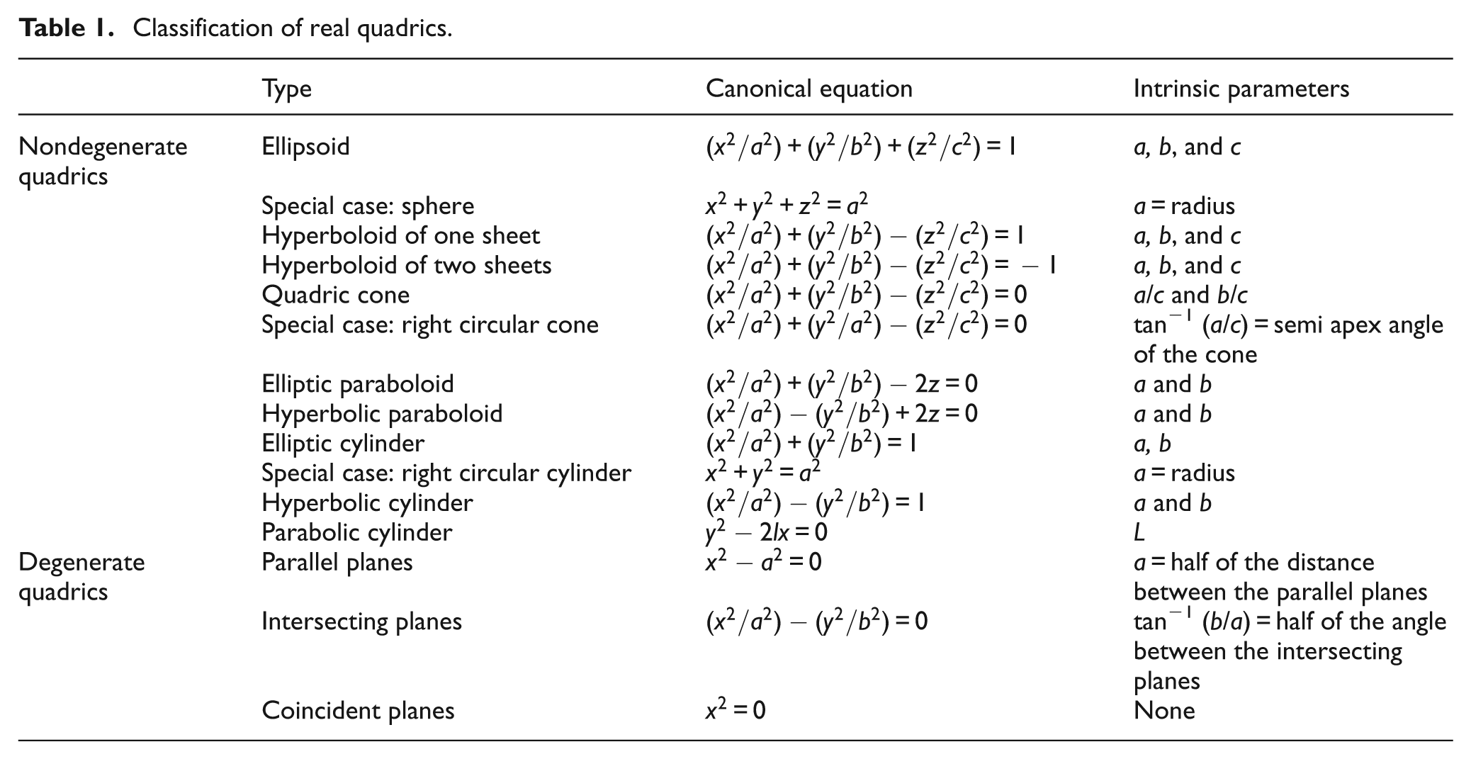
The classification theorem also provides a congruence theorem: two quadrics are congruent if and only if they have the same canonical equation. The last column in Table 1 lists the intrinsic parameters of these surfaces. The quadrics can be dimensioned by assigning numerical values to these parameters.
The complete classification of real quadrics plays an important role in the evolving standardized definition of “features of size.” Only six of the quadrics enumerated in Table 1 belong to one-parameter family of surfaces, namely, sphere, (right circular) cylinder, (right circular) cone, parabolic cylinder, two parallel planes, and two intersecting planes forming a wedge. They also possess an important monotonic containment property; for example, a sphere with a larger size dimension contains the one with a smaller size dimension. These and other symmetry properties covered in the next section provide the strongest scientific rationale for a standardized definition of “features of size” that will be discussed in section “Size tolerancing.”
Classification of continuous symmetry
The notion of symmetry greatly simplifies the task of relational dimensioning because we then need to prove only a limited number of congruence theorems. The simplification depends on some important classification theorems on the connected Lie subgroups of the rigid motion group and their corollaries on the classification of continuous symmetry of surfaces.7,8,10,11 These and related theorems were rigorously proved only over the past 15 years.
To gain an intuitive appreciation for the role of symmetry, consider the problem of positioning an arbitrary object, such as a chair, in three-dimensional space. It requires six dimensions—three for translation and three for rotation. Now consider positioning a sphere in space. It seems to require only three dimensions, which are needed to locate the center of the sphere. We do not need any dimension to specify rotation because the symmetry of the sphere renders all rotations about its center irrelevant for positioning purpose. Finally, consider the task of positioning a sphere relative to a (unbounded) plane. A little reflection indicates that we need to specify only one dimension, namely, the distance between the center of the sphere and the plane. This drastic reduction in the number of needed dimensions is due to the fact that the plane also possesses some symmetry because it remains invariant under all translations along the plane and all rotations about any axis perpendicular to the plane.
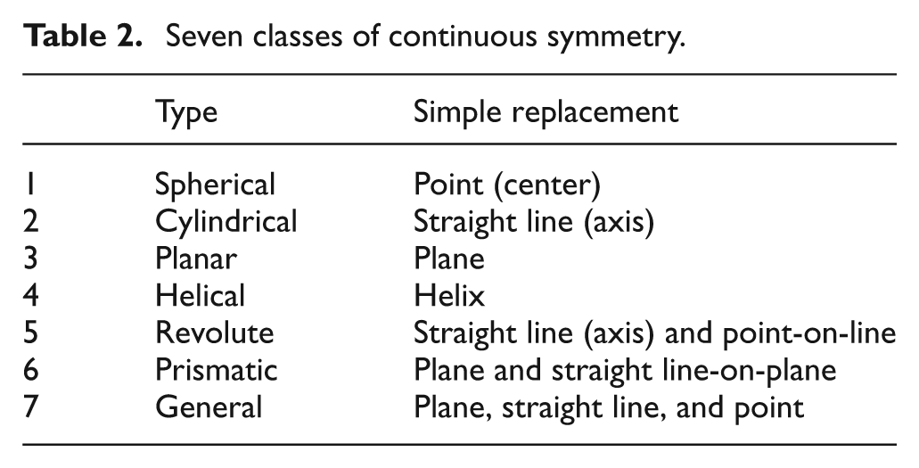
Table 2 shows the seven classes of continuous symmetry. This is a complete classification in the sense that any surface, in fact any set of points encountered in engineering, belongs to one and only one of these seven classes. These are also called invariant classes because symmetry is defined by invariance; for example, a cylinder remains invariant under all translational motions along its axis and all rotations about its axis. This is true about the axis as well because it also remains invariant under these motions. There is a powerful theorem7,8 that reduces the problem of relative positioning of any two sets to the relative positioning of their simple replacements, as shown in the last column of Table 2. These results provide the scientific basis for standardized datums and datum systems that will be described in section “Datums and datum systems.”
Seven classes of continuous symmetry.
Computational coordinate metrology
Computational coordinate metrology involves the development and implementation of reliable algorithms to fit, filter, and perform other types of computations on discrete geometric data collected by coordinate measuring systems. Over the past 20 years, it has grown into a separate research discipline. Several international conferences and journals now list computational metrology as a distinct topic of interest. Of the many research results that deal with computational coordinate metrology, those that address fitting and filtering are the most relevant to the verification standards for conformance to tolerance specifications. Mathematically and computationally, fitting is an optimization problem and most of filtering is a convolution problem.12–21 The filtering techniques also form the mathematical basis for surface texture characterization.
The scientific and technical advances in hardware for coordinate measurements and software for processing the data collected from these measurements have forced a rethinking of tolerance specification standards. To illustrate this fact, let us consider the problem of fitting a plane to a set of points in space. If d1, d2, …, dn are the perpendicular (Euclidean) distances of n input data points from a plane P, then we can define the distance between this set of points and the plane P using the generic lp norm

The individual distances can be signed, in the sense that points lying on one side of the plane can be assigned positive distances and the points lying on the other side can be assigned negative distances. The l1 norm is then just the sum of the absolute values of the individual distances. The l2 norm is the square root of the sum of the squares of the distances. The l∞ norm is the maximum of the absolute values of the distances; to see this, we need to look at the definition of the lp norm as p tends to infinity. Table 3 presents a set of plane fitting problems posed as optimization problems for the objective function, as shown in equation (2). In the ISO parlance, the l2 norm is known as the Gaussian norm and the l∞ norm is known as the Chebyschev norm.
Fitting a plane P to a set of points in space.
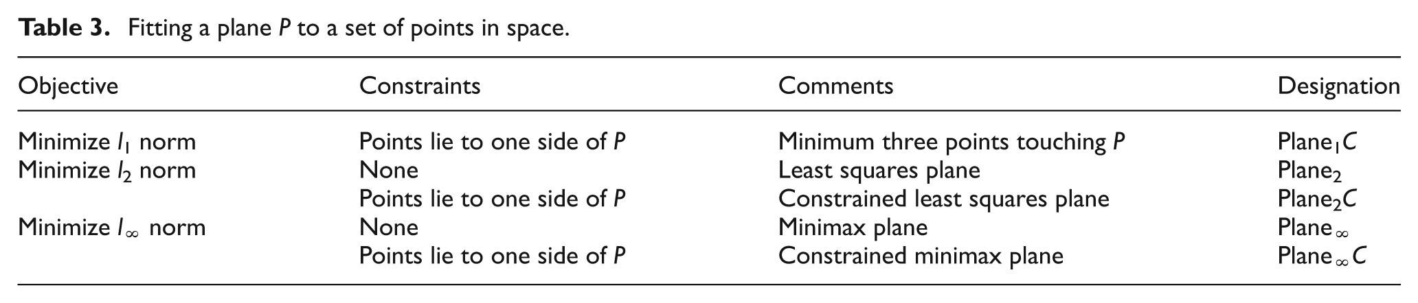
Algorithms for computing Plane2, Plane∞, and Plane∞C in Table 3 have been well developed in the literature. 13 Of these, the least squares plane, designated as Plane2, is the most widely implemented, tested, and used in industry. 22 Plane1C conforms to the ASME Y14.5:2009 standard 23 for the establishment of primary planar datum because it guarantees a stable plane that touches at least three points. On the other hand, Plane∞C is the default primary datum plane according to the ISO 5459:2011 standard. 24 Currently, ISO is mulling over future tolerance specification standards that will allow the designer to choose from several fitting objectives including the Gaussian norm and the Chebyschev norm. Such an expansion is also envisioned for a wide variety of geometric characteristics that will be described in section “Geometric characteristics and tolerancing.”
Size tolerancing
Historically, both the ASME and the ISO standards had recognized only sphere, cylinder, and two opposing parallel planes as the standardized features of size. These have been the only features to which size dimension and tolerance can be assigned; these have also been the only features that can be designated as datums with material conditions. These practices originated from engineering experience and were not based on any scientific rationale.
We can now provide a scientific basis for the definition of features of size and, in that process, expand their coverage.25–28 ISO has recently adopted a total of five features of size, as shown in Table 4 from one of its recent standards. Five of the six one-parameter family of quadrics discussed in section “Classification of quadrics” and five of the seven classes of symmetry (invariance classes) discussed in section “Classification of continuous symmetry” are represented in this updated standardized definition of features of size; these features also possess the monotonic containment property discussed in section “Classification of quadrics.” Parabolic cylinder, which belongs to the prismatic class, is the only one-parameter family of quadrics that did not make the list—the engineering community did not consider its use to be sufficiently widespread to warrant the “feature of size” designation.
Features of size according to ISO 5459:2011 24 .
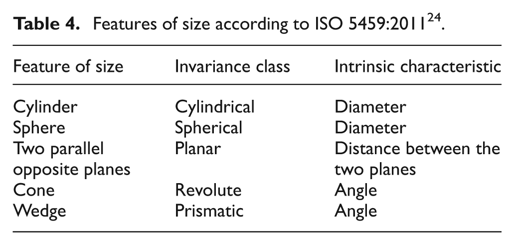
Of the five features of size in Table 4, three—namely, cylinder, sphere, and two parallel opposite planes—have linear units as the intrinsic characteristics. These are the linear sizes, and the other two features of size have angular sizes. In a recently issued ISO 14405-1 standard, 29 the linear size tolerances for cylinder and two parallel opposite planes have been expanded considerably. ISO 14405-1 allows tolerances to be specified on the following 14 different types of sizes: two-point size, local size defined by a sphere, least squares size, maximum inscribed size, minimum circumscribed size, circumferential diameter size, areal diameter size, volume diameter size, maximum size, minimum size, average size, median size, mid-range size, and range of sizes. Figure 3 illustrates one of the 14 ways in which the size tolerance for a cylindrical feature can be specified.
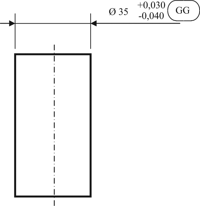
Least squares size tolerancing of a cylinder according to ISO 14405-1:2010. 29 Here, the GG modifier denotes that a Gaussian (least squares) size is being toleranced for the indicated cylinder.
The release of ISO 14405-1 standard in 2010 heralded a much needed revolution in the tolerance specification standards. Before the arrival of ISO 14405-1, there was an implicit expectation that size tolerances should be verifiable using the likes of micrometers, calipers, dial indicators, and functional gauges. (In fact, such expectations are prevalent even for all geometric tolerance specifications under the guise of “open setups” for their verifications.) Using a computerized coordinate measuring system was deemed acceptable, as long as it could be run in the “caliper mode” and with some soft-gauging capabilities. In contrast, a size tolerance specification such as the one shown in Figure 3 can only be verified by coordinate measuring systems employing least squares fitting algorithms, which are now available, thanks to scientific and technical developments in computational coordinate metrology alluded to in section “Computational coordinate metrology,” for cylinder fitting. Future ISO standards for geometric tolerance specifications will depend critically upon such fitting algorithms for their verification.
Datums and datum systems
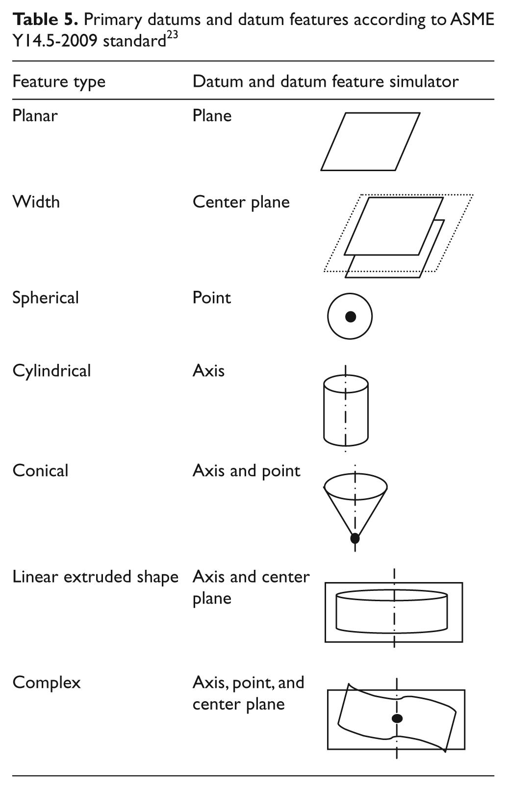
Datums and datum systems are essential for specifying tolerable variations in the relative positioning of features. As we saw in section “Classification of continuous symmetry,” classification of continuous symmetry provides a scientific basis to define datums. This has been seized upon by the standards community in recent times, as briefly described in Table 5 excerpted from the ASME Y14.5 standard issued in 2009 and in Table 6 excerpted from the ISO 5459 standard issued in 2011. These tables clearly show the classification of standardized datums on the basis of the symmetry group classification of the nominal ideal geometric features that are designated by designers as datum features.
Primary datums and datum features according to ASME Y14.5-2009 standard 23 .
Invariance classes to define datums according to ISO 5459:2011standard 24 .
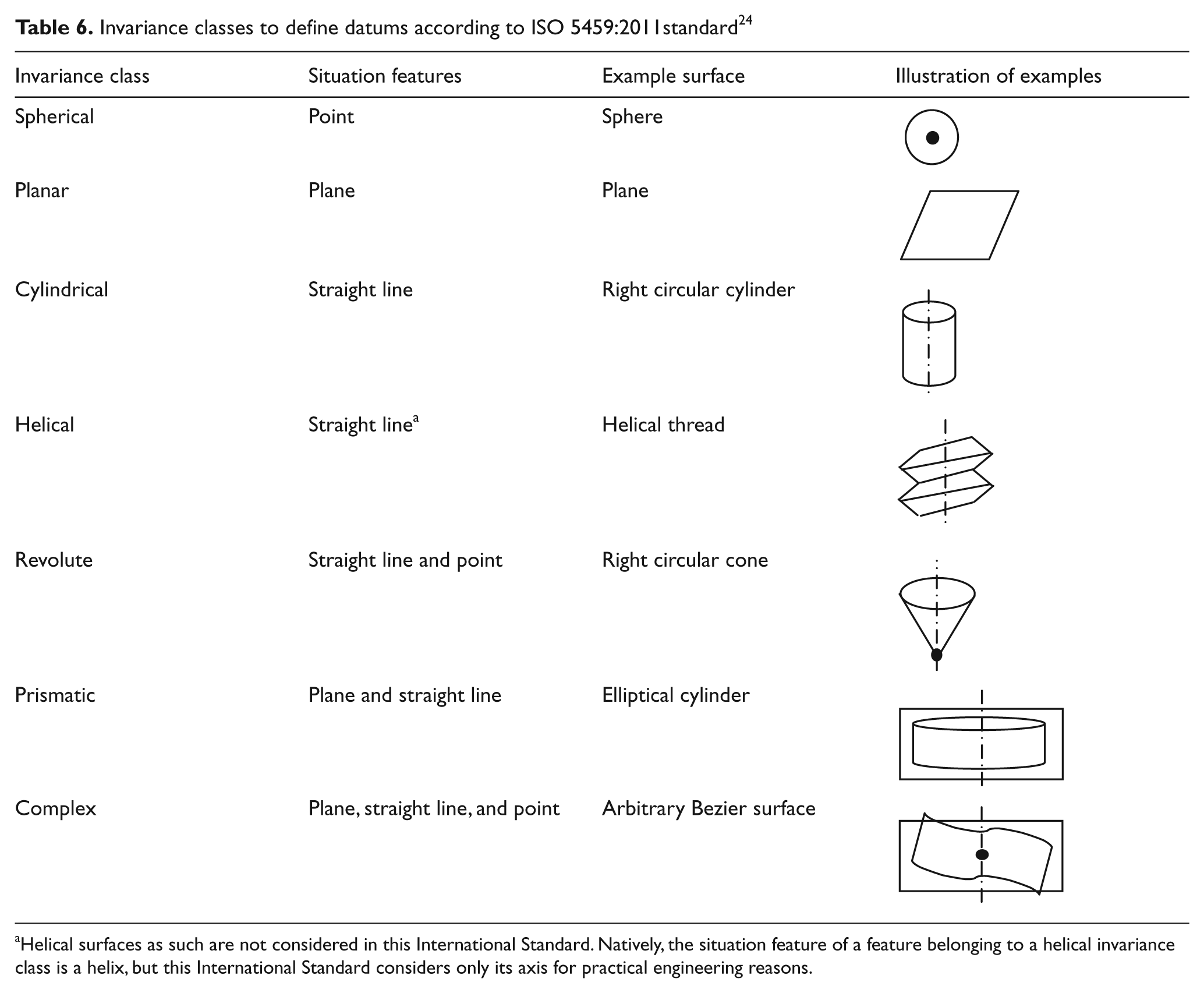
Helical surfaces as such are not considered in this International Standard. Natively, the situation feature of a feature belonging to a helical invariance class is a helix, but this International Standard considers only its axis for practical engineering reasons.
A closer examination of Tables 5 and 6 reveals the distinction between a datum feature and the associated datum. For example, a cylindrical feature can be designated as a datum feature, and its axis then becomes the datum. On an actual workpiece, the features have nonideal forms and so we need to fit ideal geometric features before the datums can be discerned. As described in section “Computational coordinate metrology,” various norms can be used to define the objective function in the optimization problem involved in such fittings. The standards currently rely upon the l1 norm and the l∞ norm, with constraints; ISO is contemplating appropriate symbology to override the default, so that other lp norms can be invoked for determining the datums.
Geometric characteristics and tolerancing
The dimensional taxonomy shown in Figure 2 was useful in structuring the theoretical development of dimensioning and geometric parameterization. It also explains the classification of geometric characteristics and tolerancing as shown in Tables 7 and 8 in the ASME and ISO standards, respectively, which have stood the test of time. The ASME classification, as shown in Table 7, refers to individual features and related features in the same way intrinsic dimensions and relational dimensions are dealt with in sections “Congruence theorems,”“Classification of quadrics,” and “Classification of continuous symmetry.” The ISO classification, as shown in Table 8, is the same as that of ASME, and it explicitly invokes the need for datums for tolerancing relative positioning.
Classification of geometric characteristics according to ASME Y14.5-2009 standard 23 .
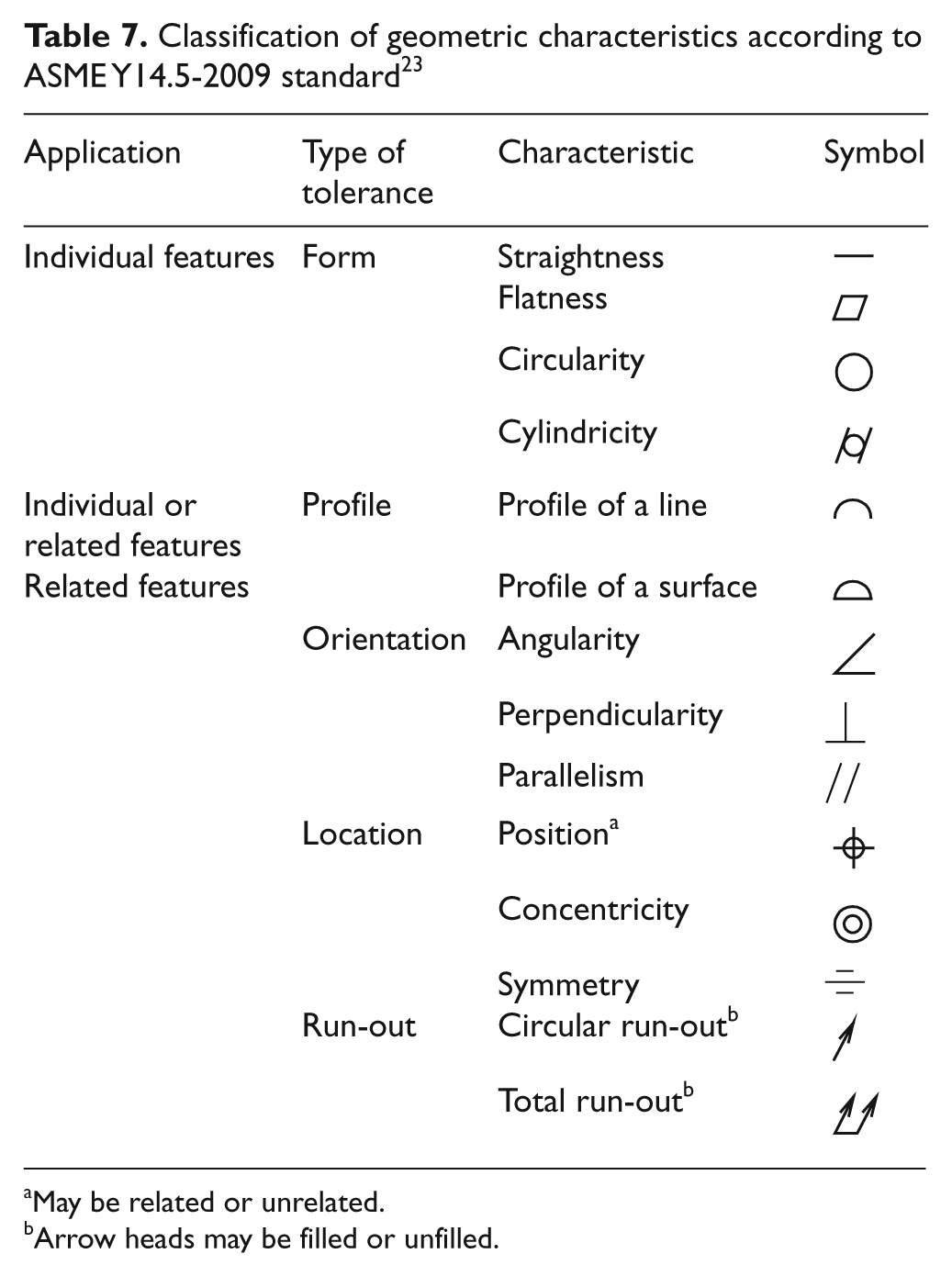
May be related or unrelated.
Arrow heads may be filled or unfilled.
Geometric characteristics according to ISO 1101:2012 standard 30 .
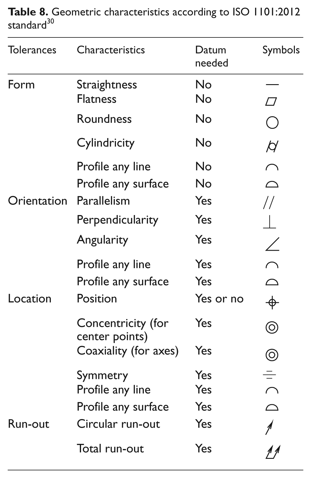
Both the ASME and ISO tolerancing semantics of geometric tolerances shown in Tables 7 and 8 are based on tolerance zones. ISO is now considering several ways to expand the syntax and semantics of geometric tolerances as it did for size tolerancing. For example, in the future, flatness tolerance can be specified to limit the root mean square deviation (i.e. standard deviation) of the points on an actual feature from a Gaussian (least squares) plane fitted to the feature.
Summary
This article described the role of science in classifying and rationalizing the some of the past and current dimensioning and tolerancing practices and in paving the way for future development of dimensioning and tolerancing standards. Motivated by the industrial need, the last two decades have witnessed considerable mathematical and algorithmic advances, and the dimensioning and tolerancing standards are well poised to exploit these advances in at least four distinct areas.
First, computer-aided dimensioning and CAT software systems can be based on data models that are provably complete and algorithms that are provably correct. Second, these data models can form the basis for standardized exchanges 31 that enable interoperability among engineering information systems. Third, computer-aided manufacturing systems can consume the tolerancing information automatically for smarter numerical control of machine tools. Fourth, computer-aided inspection systems can use the tolerancing information to generate and execute inspection plans automatically.
In the next few years, we are likely to witness major expansions in the ISO tolerancing standards, 32 assisted by scientific developments similar to those outlined in this article and subsequent codification of concepts and terminology.33–35 Industry will struggle with the magnitude of such changes, and there will be a great demand for education of the industrial workforce and college students in these new standards and practices. We might well look forward to another two decades of fun and profit.
Footnotes
Acknowledgements
The author would like to acknowledge the contributions of various subject matter experts in the ASME and ISO standards committees to the developments reported in this article. Any mention of commercial products within this article is for information only; it does not imply recommendation or endorsement by NIST.
Funding
This research received no specific grant from any funding agency in the public, commercial, or not-for-profit sectors.