
Abstract
The optimal fixture scheme can effectively reduce the deformation of sheet metal parts in the normal direction of their main plane. The fixture layout design requires a great deal of finite element analysis, which limits efficiency and quality of fixture design. This article proposes a two-stage method to decrease the number of finite element analyses for fixture layout design. First, three locating points are generated by using particle swarm optimization based on the rigid model. Second, the other points are optimized by establishing a response surface modeling based on radial basis function. Finally, through the case of rear bracket plate, this work elaborates two-stage fixture locating scheme design process. The results show that the two-stage method has good simulation effect and higher prediction accuracy.
Introduction
Problem description
Sheet metal parts are widely used in many products such as automobiles, airplanes and appliances. Dimensional quality, which measured by its own variation, fixture configuration and assembly process variations, is an important factor influencing the final geometry of sheet metal assemblies. During manufacturing of a new product, the fixture-related dimensional errors constitute up to 40% of all dimensional variations during preproduction period, up to 70% during launching and 70%–100% during one and two shifts of production. 1 Therefore, fixture layout design is important in manufacturing to figure out the best configuration of a product to guarantee that the quality of a product or an assembly is insensitive to dimensional variations from components and fixtures.2,3
Auto-bodies are assembled in a multistation sequential process, where at each station, fixtures are applied to locate and clamp the parts. Therefore, the fixtures play a critical role in controlling the position of the components and subassemblies on each station and on the final product quality.
Related work
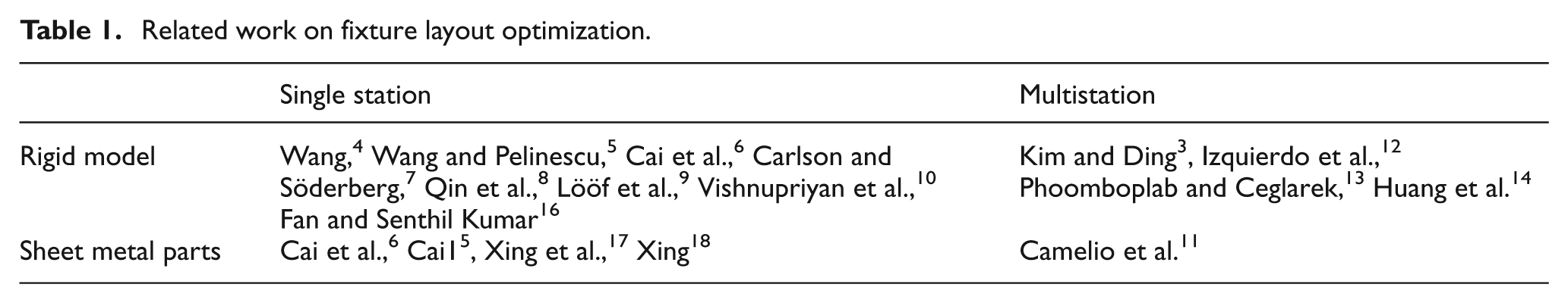
Many scholars have studied fixture design problems since 1990s. The related work for fixture design is shown in Table 1. Wang 4 built an arbitrary three-dimensional (3D) geometry model but restricted in discrete domain of locations for placing fixture elements of nonfrictional contacts. Wang and Pelinescu 5 optimized the fixture layout through maximizing the determinant of information matrix. Cai et al. 6 presented a robust fixture layout by using Euclidean norm of fixture sensitivity index. Carlson and Söderberg 7 proposed a method of optimizing locating scheme through using the quadratic sensitivity equation. Qin et al. 8 proposed to optimize fixture layout based on the degrees of freedom constrained. Lööf et al. 9 presented an approach for optimizing positions of locators in a locating scheme to maximize robustness in defined critical dimensions. Vishnupriyan et al. 10 proposed a genetic algorithm (GA) based on optimization method to get a layout of error containing locators for minimum machining variation satisfying the tolerance requirements and providing deterministic location. Above methods were used in deterministic workpiece location at single-station fixture design.
Current researches on fixture design focus on multistation assembly processes. Camelio et al. 11 suggested using influence coefficient to analyze the impact of fixture design to sheet metal assembly variation and showed that fixture deviation had greater influence on assembly variation than part deviation. According to Camelio et al., 11 assembly variation depends on fixture positions in the presence of fixture variation. Therefore, the fixture layout should be optimized for reducing the final product tolerance. Kim and Ding 3 proposed a methodology to design multifixture layouts in multistation assembly based on a station-indexed state-space model. Izquierdo et al. 12 proposed a method to achieve the robustness of fixture layout design by an optimal distribution of locators in a multistation assembly system. Phoomboplab and Ceglarek 13 presented a two-step optimization method to improve process yield through determining an optimum set of fixture layouts for a given multistation assembly system. Huang et al. 14 proposed an alternative sequential space filling strategy, which adopted sampling approaches to search optimal designs. All the above methods are based on the assumption of six-point locating principle; however, the assumption does not satisfy sheet metal components due to deformation during welding process. Cai et al. 6 proposed a new “N-2-1” locating principle and proved that the new locating scheme was more suitable for sheet metal parts than the “3-2-1” locating principle. With the application of the principle of “N-2-1,” Cai 15 presented the applications of a robust design strategy in locating pin layout design for sheet panels. The objective function of fixture scheme optimization applied the robust fixture layout model. 6 Fan and Senthil Kumar 16 studied that fixture locating layout was carried out with the robust design approach by combining the Taguchi method and the Monte Carlo statistical method in order to increase the quality of the final workpieces. Xing et al. 17 used the heuristic algorithm to optimize locating schemes and applied the radial basis function (RBF) to reduce the number of the finite element analyses (FEAs). Xing 18 also proposed a hybrid heuristic and orthogonal algorithm to optimize locating positions, which could only generate the satisfactory solution.
Related work on fixture layout optimization.
Objective and organization
Methods of Xing et al. 17 and Xing 18 also conducted lots of FEA for the “N-2-1” locating principle but did not provide global optimal solutions for fixture layouts. In order to improve optimization precision and efficiency, this work presents a two-stage method to optimize the fixture layout of sheet metal parts. First is to generate the three optimal points based on a six-point locating principle using particle swarm optimization (PSO) to increase the optimization efficiency. Then, the other locating points are optimized through establishing a response surface modeling (RSM) based on RBF to decrease the numbers of FEA.
The remainder of this article is organized as follows. Section “Fixture scheme and evaluation function” presents fixture schemes and evaluation function of fixture layout optimization. Section “Fixture scheme optimization by PSO” uses the PSO algorithm to optimize three points based on rigid model. In section “Fixture scheme optimization based on RSM,” the other points are optimized by establishing an RSM based on RBF. The proposed methodology is illustrated by an example in section “Case of fixture design.” Finally, section “Discussions of the two-stage method” draws the conclusions.
Fixture scheme and evaluation function
According to Cai et al., 6 the “N-2-1” principle can be used to reduce the deformation in the normal direction of the main plane. This study uses the “4-2-1” locating scheme to optimize the fixture layout for simple sheet metal part, as shown in Figure 1. In order to compare the study results of the two-stage method and the hybrid heuristic and orthogonal algorithm, all the characteristics are exactly the same with those in Xing. 18
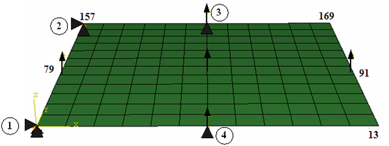
Sheet metal part (meshed).
The dimension of the sample is 300 mm × 300 mm with thickness of 1 mm. Young’s modulus is 20,700 N/mm2 and Poisson’s ratio is 0.3. To analyze deformation in the normal direction of the main plane, five units of force is applied at the center points of four edges and whole plane, respectively (Figure 1). The plane is meshed by 12 × 12 elements, with a total of 169 nodes. Each node can be selected as one locating point, thus the optimization complexity is of
In order to evaluate different fixture schemes, the displacement of all the nodes in the surface is used as the objective function as shown in equation (1)

where F(
According to Cia et al., 6 the longer the distance between location points, the smaller the variation of the workpiece; thus, the principle of “2-1” can be applied first without influences of deformation of main plane. The positions and directions of the three nodes are (−150, −150, 0, 0, 1, 0), (−150, −150, 0, 1, 0, 0) and (−150, 150, 0, 1, 0, 0). The node numbers are 1, 1 and 157, respectively (as shown in Figure 1). The other four points are optimized according to the flowchart of the two-stage method.
The two-stage method is described in detail in the following sections. Since the “2-1” points are fixed, the three locating points are optimized by using the PSO algorithm based on rigid model, and then the other points are acquired through RSM based on RBF.
Fixture scheme optimization by PSO
This section focuses on the process of fixture layout optimization based on rigid model. The three optimized points are in same directions (0, 0, 1) but different positions. The results of fixture locating scheme can be calculated by the robust fixture design proposed by Cai et al. 6 If the directions of “N” and “2-1” are not orthogonal, the algorithm for robust fixture design can be used to calculate different directions and positions of locating points.
Objective function for PSO
The translational and orientation variations at any key product/process characteristic point (KPC) can be expressed as a vector

where the Jacobian is
The purpose of fixture design is to choose set of locating points to reduce the

where
Particle coding and decoding
The PSO suggested by Kennedy and Eberhart 19 was based on observations of social behavior of animals, such as bird flocking where the PSO algorithm adopted a population of candidate solutions, called particles, with their positions initialized randomly from the search space. Each particle is assigned with a velocity, also initialized randomly, according to its own experiences and those of its companions. One of the advantages of the PSO method is that previously visited best positions were remembered.
The particle is generated from the node numbers, which are decomposed into x and y directions. As the plane part of Figure 1 is meshed by

where
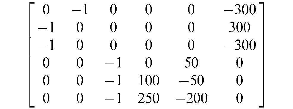
For example, one particle is (050707081011). Then, the first node number is 97, the second node number is 112 and the third node number is 154. The coordinates and directions of three points are (−25, 25, 0, 0, 0, 1), (25, 50, 0, 0, 0, 1) and (100, 125, 0, 0, 0, 1), respectively. Thus, the Jacobian matrix is shown below and the objective function is 5.53
In the initialization of particle swarm population, if there points in any two or three overlap, it is an unfeasible particle that can be assigned with a bigger value such as 1000.0 to reduce the evolution of these particles.
Updating the particle position and velocity
At each iteration k, the particles are represented by a vector

The vector

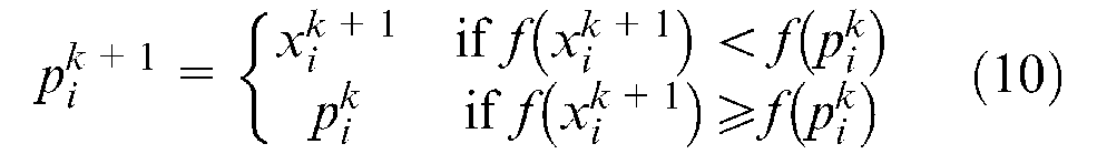
Each particle changes its position

where
At each iteration k, the position

The velocity

The parameter
Flowchart of the PSO
The PSO algorithm maintains a population of particles. The PSO starts with a random population of particles, then generates new populations of particles through updating the positions and terminates when the stopping condition is met. The flowchart of the PSO is shown in Figure 2.
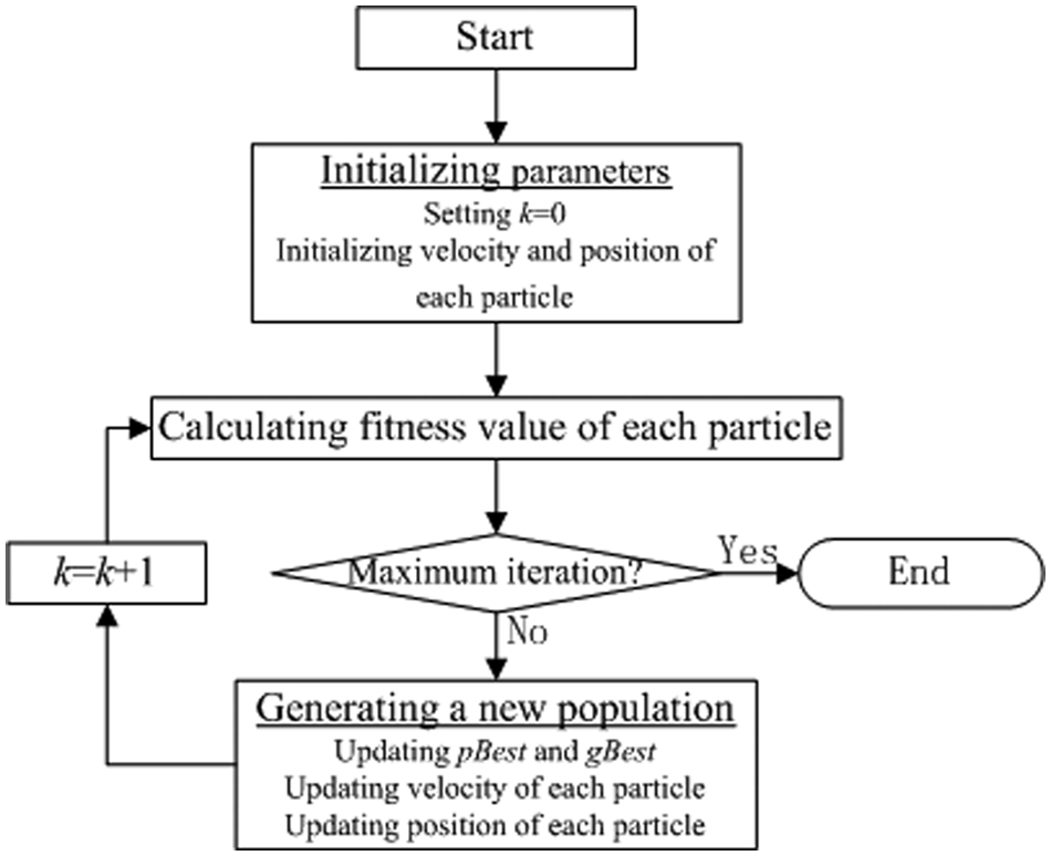
Flowchart of PSO.
Step 1. Initializing parameters. Step 1-a: Initializing iteration counter k = 0. Step 1-b: Initializing N random positions of theparticles Step 1-c: Initializing N random velocities Step 1-d: Initializing N
Step 2. Evaluating particles. Step 2-a: Checking the feasibility of particles. Step 2-b: Calculating the fitness value of each particle Step 2-c: Setting
Step 3. Judging whether the stop condition is met. If the maximum iteration is met, the algorithm terminates; otherwise the algorithm goes to step 4.
Step 4. Generating a new population of PSO. Step 4-a: Updating Step 4-b: Updating Step 4-c: Updating Step 4-d: Updating
Step 5. Repeating from step 2 to step 4.
Three-point optimization of the sheet metal part
In order to optimize the three locating points, the PSO first sets fifty particles. The maximum iteration can be set to 50. According to the flowchart of the PSO, the optimization process of the minimum fitness value is shown in Figure 3.
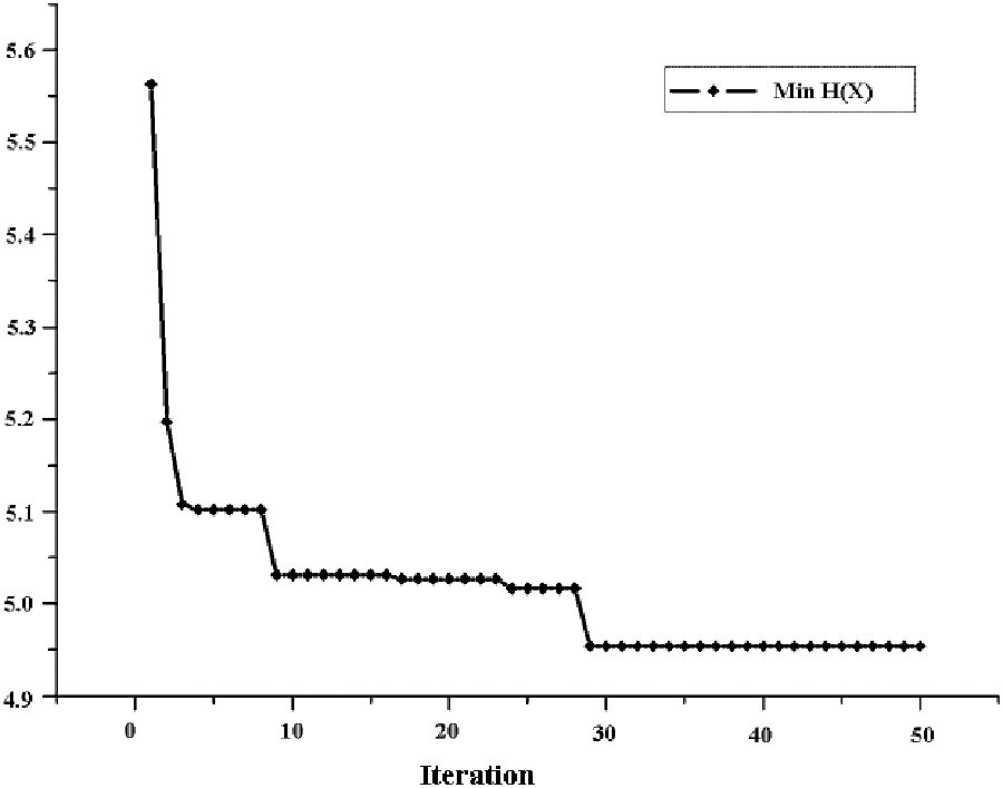
Curve of the fitness value.
According to Figure 3, the minimum fitness value is not continuously decreasing because the PSO algorithm easily falls into local optimal solutions. Therefore, the coefficients of particle velocity should be adjusted when the minimum fitness value stays the same during several iterations. The optimal particle is (000306121203) according to the flowchart of the PSO algorithm, thus the three nodes are 40, 163 and 52 by decoding the particle, whose coordinates and directions are (−150, −75, 0, 0, 0, 1), (0, 150, 0, 0, 0, 1) and (150, −75, 0, 0, 0, 1), respectively. In this case, the objective value is
Fixture scheme optimization based on RSM
In the final section, the three points are generated based on the PSO. Then, the other points are optimized by using an RSM based on RBF in this section. Commonly, RBF includes Gaussians, thin-plate splines and multiquadrics, of which multiquadrics function can be utilized in handling aircraft shape design problem of surface fitting. 21 Since the part deformation is very complex in different fixture schemes, the study uses the multiquadrics function to establish the RSM between the part deformation and fixture schemes. The multiquadrics function is shown in equation (11)

The above function has two main variables:
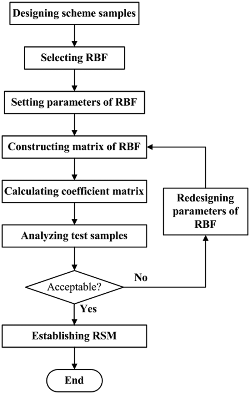
Flowchart of response surface model.
To construct the RSM, the first step is to design fixture layout samples, which are selected by using interpolation. In this work, the samples are equally spaced nodes in x and y directions. The next step is to set multiquadrics function as a basis function. Based on the above conditions, the coefficient matrix is established between fixture schemes and node displacements. When the RSM is created, the fitting results can be calculated by inputting the test samples. Then, the results can be compared to the value calculated by the FEA. If the error can be accepted, the operation will stop; otherwise, the parameters of RBF would be reselected.
For Figure 1, five points are set in x and y directions, then 25 samples are used to establish the RSM. The node numbers of all samples are shown in equation (12)

The objective function value can be calculated based on the samples. The RSM is established through the flowchart (Figure 4). The relationship of the node number and part deformation is shown in Figure 5.
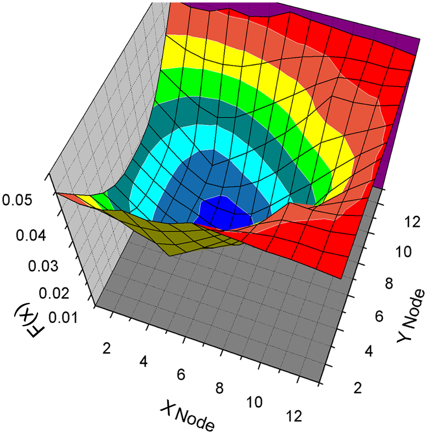
The response surface model of the sheet metal part.
According to Xing, 18 the steps of the hybrid heuristic and orthogonal algorithm can be described as follows:
Step 1. Determining the initial fixture layout.
Step 2. Selecting one locating point to be optimized.
Step 3. Designing the samples of fixture layouts and calculating the results by the FEA.
Step 4. Establishing the RSM and optimizing the locating point.
Step 5. Repeating from step 2 to step 4 until four points have been optimized.
Step 6. Optimizing the final fixture scheme by using orthogonal design.
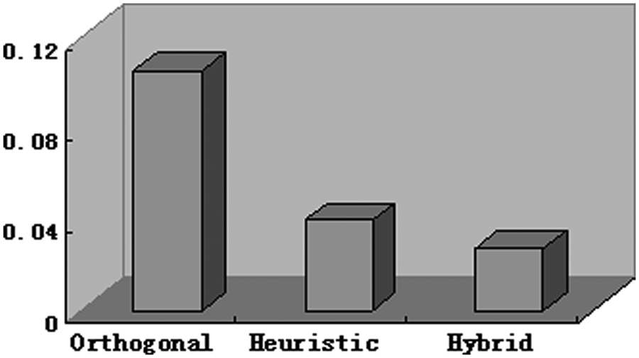
The objective value of evaluating deformation can be compared by the above steps for different methods, as shown in Figure 6. The objective values are 0.105 by the orthogonal design, 0.039 by the heuristic algorithm and 0.027 by the hybrid algorithm. Based on the results, the hybrid algorithm is proved to have the best optimization precision.
Sheet metal deformation under optimal locating layout.
As shown in Figure 5, the optimal solution is
Case of fixture design
This work also uses the rear bracket plate part in Xing 18 to illustrate the operation of the two-stage method. The rear bracket plate part influences the assembly variation of rear taillight. Thus, it is very important to design the fixture layout of this part. Figure 7(a) shows the rear bracket plate part, whereas Figure 7(b) shows the 18 units of force that will cause the part to deform.

Rear bracket plate components: (a) the rear bracket plate and (b) the forces and the constraints.
The layout of the rear bracket plate uses the “4-2-1” principle, in which “2-1” utilizes the original hole (pin) and slot (pin). The hole (pin) can be decomposed into two points: (5281.6, −694, 1157.5, 0, 1, 0) and (5281.6, −694, 1157.5, 0, 0, 1). The slot (pin) can control one degree of freedom, and the point is (5318, −668, 867, 0, 1, 0). According to the two-stage method, the particle swarm algorithm optimizes the first three points. The final point is acquired through establishing the RSM.
According to the flowchart of PSO, the number of particle population is set to 50 and the maximum iteration is 50. Because the main plane of rear bracket plate is very complicated, it is very difficult to optimize the three points according to the node numbers. The approximate area should be confirmed based on the main plane of the part, as shown in Figure 8. The four vertexes can be calculated from the dimensions of the part.
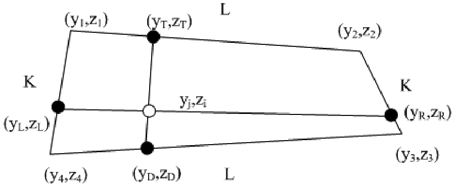
Approximate area of the rear bracket plate.
The approximate area is meshed by
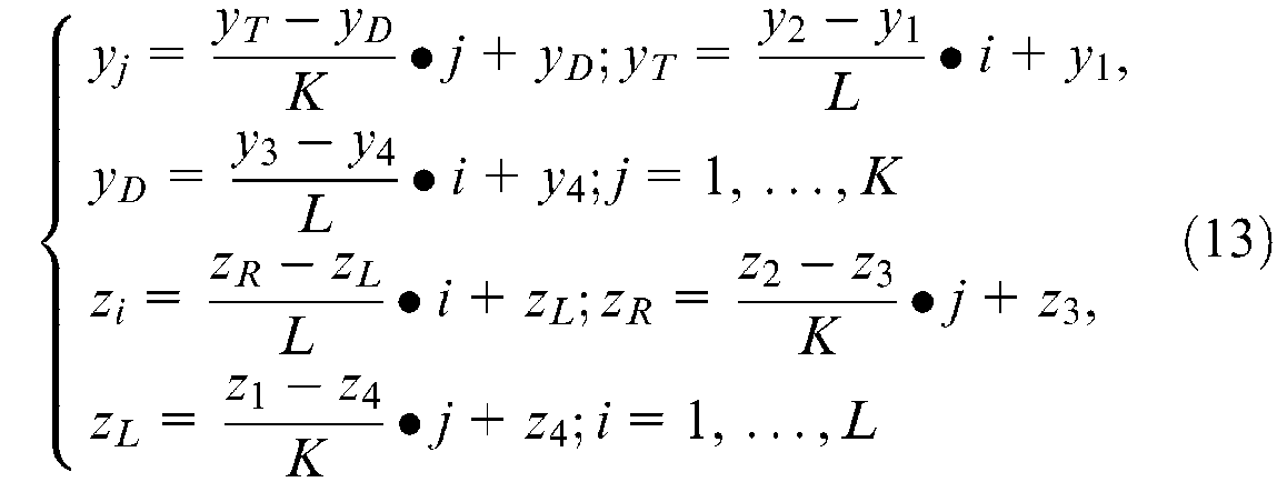
In this work, K and L are set to 25 and 50, respectively. The coordinates of the four vertexes are (−796.7, 830), (−744, 1180), (−643, 1172) and (−643.8, 803). The optimal particle is (255000292500) and the minimum objective value is 42.7. According to equation (10), the three points are (P1: 5305.7, −744, 1180), (P2: 5311, −640.8, 1034.6) and (P3: 5390.1, −795.7, 830). The curve of fitness value is shown in Figure 9.
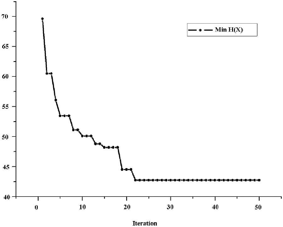
Curve of the minimum fitness value.
The objective function value is not the optimal in the principle of optimal scheme based on PSO since the part is too complicated. To overcome the contradiction of part deformation and variation propagation, the work utilizes the following steps to select the three points:
Step 1. Analyzing the center point P0 of the existing three points (P1, P2 and P3).
Step 2. Setting partitions from the center point to each vertex is the same.
Step 3. Analyzing the part deformation by FEA.
Step 4. Calculating the objective function value according to equation (1).
Based on the above steps, the three best points are (OP1: 5137, −739, 867.8), (OP2: 5130, −638, 1028) and (OP3: 5283, −702, 1124), as shown in Figure 10.
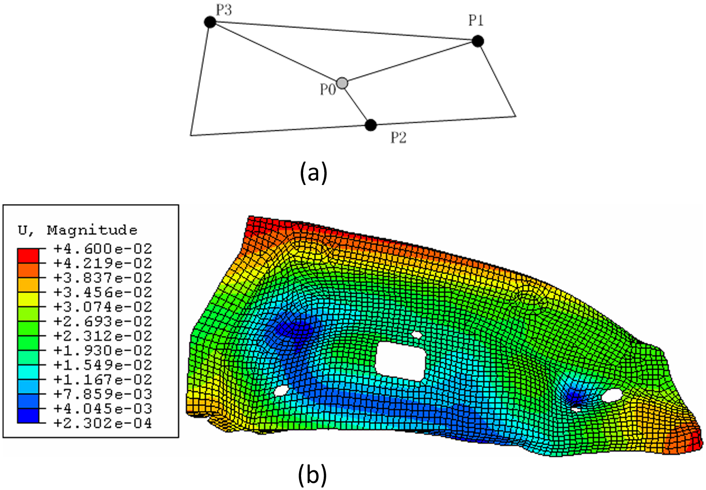
(a) Fixture scheme based on rigid model and (b) part deformation of new optimal three points.
In this study, the multiquadrics function is used to establish the RSM. The 40 nodes are designed as the samples of fixture schemes, which are shown in Figure 11(a). The RSM is created according to Figure 4, which is expressed as Figure 11(b) through inputting every node coordinates.

Response surface model of the rear bracket plate: (a) fixture scheme based on rigid model and (b) deformation of new optimal three points.
The objective function value is 0.441 using the two-stage method in the “4-2-1” principle. The best value is 1.26 according to literature. 18 The optimization accuracy is largely improved and the times of the FEA are decreased. Figure 12 compares the optimization fixture schemes of the two methods: (1) the part deformation of optimization fixture scheme by heuristic algorithm and (2) the part deformation of optimization fixture scheme by the two-stage method. It can be seen that the efficiency of the two-stage method is better than that of the heuristic algorithm.
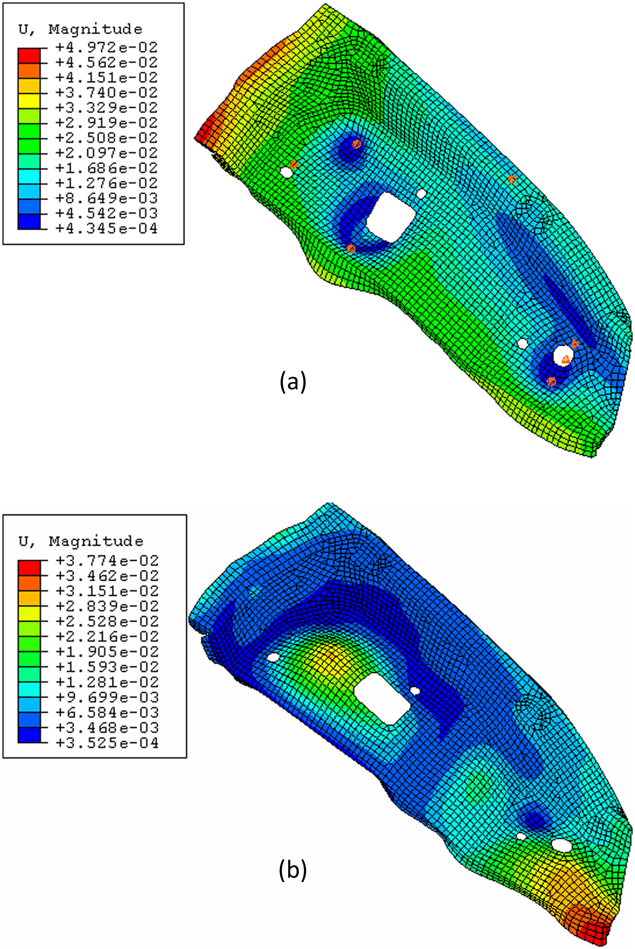
Comparison of the part deformation through different methods: (a) part deformation by the heuristic algorithm and (b) part deformation by the two-stage method.
Discussions of the two-stage method
The case study of the rear bracket plate in section “Case of fixture design” illustrates the effectiveness of the two-stage method. The proposed method can improve optimization precision and efficiency for fixture layout designing, especially in the “4-2-1” principle. For example, the number of the FEAs for the simple sheet metal part decreases from 145 to 25 and the objective value of the deformation in normal direction of main plane reduces from 0.027 to 0.00598. The two-stage method is divided into two steps: (1) three points are generated by using the PSO algorithm and (2) the other points are optimized through the RSM. This could not lead to global optimization solutions in theory. Instead, it leads to satisfactory solutions.
Since the FEA for sheet metal parts takes a long time, the global optimal results are almost impossible to be calculated by the enumeration method, the GA or other algorithms. Each FEA for the sheet metal part (Figure 1) takes about 50 s (Intel Pentium Dual CPU, 2.20-GHz, 2.19-GHz, 0.99-GB random-access memory (RAM)), including editing of input files of ABAQUS, analyzing the finite elements and reading displacements of all nodes, which even based on the operation of secondary development of ABAQUS. In this case, the complexity of the sheet metal part is
Conclusion
The fixture layout is critical for product quality. In order to reduce optimization time of fixture layout, the two-stage method is proposed to optimize fixture scheme. Three locating points are generated by using PSO algorithm based on rigid model, and the other points are optimized through RSM based on RBF. The two-stage method can generate satisfactory solutions. Finally, the rear bracket plate is utilized to illustrate the flowchart of the two-stage method. The results show that the two-stage method can improve the optimization efficiency and greatly reduce the number of FEAs. The method of this article is effective for designing fixture layout, which differs from the current methodologies in three aspects:
The two-stage method is proposed to optimize the fixture layout of sheet metal parts, which can improve the optimization precision and efficiency.
The linear variation analysis model is applied to optimize three points in the flowchart of the PSO algorithm, which can generate the global fixture layout based on the rigid model.
The RSM based on RBF is used to decrease the number of FEAs for improving the optimization efficiency.
Footnotes
Funding
This study was supported by National Natural Science Foundation of China (51105241) and Shanghai Natural Science Foundation (11ZR1414700).