
Abstract
For complex mechanical systems, to overcome design inconsistencies, it is becoming more and more necessary that product design system is effectively integrated with various analysis models and tools from multiple engineering domains at different design stages. In this article, a Holistic Product Design and Analysis Model, which is well supported by Top–Down design method, is conceptualized to define design and analysis integration at different levels, which will help enhance engineering design and analysis interoperability and integrate the design methods and analysis tools across multiple engineering domains. It is based on four design levels: system, subsystem, machine and component designs; at each level, design and analysis models are integrated under a Generalized Multirepresentation Architecture supporting design, analysis and optimization appropriately. For cross-level integration from top to bottom, the design models are transferred and mapped with more structural and geometric details, while analysis models obtain more detailed design constraints from the top levels. This new architecture has been developed and demonstrated with an application in a railway vehicle system design, although its optimization components have not been fully implemented. This model can be used for general mechanical product system design.
Keywords
Introduction
In a complex mechanical design process, computer-aided design (CAD) and computer-aided engineering (CAE) models are becoming increasingly important. CAD models can be used to describe the product structure and shape (or geometry), while CAE models can be used to predict the product behaviors and verify the product performances. The CAE models, such as multibody dynamics simulations, are often used to simulate the behavior of the whole interconnected multibody system and to determine the sizes of actuators and reaction forces between parts, while various finite element analysis (FEA) models are widely used to study a single component (or a machine) of a mechanical system in detail. The results of dynamics simulations can then be used in FEA-based structural design of parts. So, the effective integration of CAD and CAE models can reduce the need for expensive physical prototyping and hence shorten the product development time and reduce the product development cost.
However, CAD and CAE are different in both practice and research, 1 and their models are heterogeneous. Inconsistent problems of design data, data loss and redundancy during the transformation from CAD to CAE or vice versa are caused because of the heterogeneous feature of CAD and CAE. Some of the major issues are as follows: (1) heterogeneous data structure of CAD and CAE, (2) data losses from CAD to CAE, (3) the conflict between complex shape geometry and simple analysis model, (4) different information supplements in CAE such as dynamics analysis and FEA, (5) lack of topology information for dynamics analysis and (6) difficulties in automation design process. Therefore, there is a need to establish an engineering design and analysis integration model to define design description, to enhance engineering design and analysis interoperability and to integrate the design methods and tools.
In order to solve the problems, a considerable body of research has been made so far. Mockp and Fenves 1 classified them into three categories: object-oriented modeling techniques, CAD-FEA integration and multiview models. Research at the macroscopic-view level aims to establish new product life cycle data, 2 interaction models and a data exchange standard, such as Standard for Exchange of Product Data (STEP), which can be implemented with object-oriented modeling techniques, but this requires some fundamental changes of the current CAD and CAE systems. To verify these models against a variety of technical artifacts without a good support from commercial CAD and CAE systems is a great challenge. At the microscopic-view level, research is more concerned about CAD and FEA integration. It lacks a system view of complex mechanical product design processes. How to integrate the design and analysis models at different levels from different engineering domains in a general mechanical product design process still presents a challenge.
The focus of this research is to establish a Holistic Product Design and Analysis (HPDA) Model, which supports multiple-level integrations of design and analysis models. It is composed of four levels: system, subsystem, machine and component levels. At the system level, the design focuses on technology selections, system configuration or layout design of a mechanical product system based on social, economic, political, environmental and technical constraints. At the subsystem level, the design is more concerned with the dynamic behaviors of the mechanical system. At the machine (product) level, the design is focused on the structural, geometrical and interaction design of the product and its engineering analysis, such as structural analysis and optimization. At last, at component level, the design details the structural and geometric design of mechanical parts and their analysis, such as stress and fatigue. HPDA model is underpinned by a Generalized Multirepresentation Architecture (GMRA) with the extension from the Multirepresentation Architecture (MRA) 3 to include optimization. In order to evaluate the proposed HPDA model and the GMRA architecture, a railway vehicle design and analysis platform based on multibody system design and the wheel–rail contact theories was developed. The HPDA model has been effectively applied into this platform development.
The structure of this article is as follows: the current research efforts are detailed in section “Literature review.” Section “HPDA model” represents the proposed HPDA model in detail. Section “GMRA and an example” describes the GMRA and its implementation based on STEP by EXPRESS and EXPRESS-G. A design and analysis package for railway vehicle based on GMRA is introduced in section “Design and analysis package of railway vehicle based on GMR.” A case study is described in section “Case study” and the results are discussed in section “Discussion.” Finally, the conclusions are drawn in section “Conclusions.” A nomenclature is appended for easy reading.
Literature review
Related work can be divided into three categories: object-oriented modeling techniques, CAD-FEA integration and multiview models. 1 For object-oriented modeling techniques, the research in the field is concerned with mapping of a generic design process and a general product data model such as “Core Product Model” (CPM) 2 based on object-oriented modeling paradigm with benefits of reusability and modularity. For instance, Patil 4 developed Product Semantic Representation Language (PSRL) to enhance interoperability in CAD/CAE. Peak et al. 3 presented a MRA for the integration of CAD and CAE. The MRA attempts to automate routine analysis by bridging the design–analysis gap with four bricks: Product Model (PM), Product Model–Based Analysis Model (PBAM), Analysis Building Blocks (ABBs) and Solution Method Model (SMM). However, the proposed architecture focused on a single component design level, not suitable for dynamics analysis, and the PM model is required to represent all life cycle data associated with the product. Following this work, Tamburini 5 complemented MRA by presenting an Analyzable Product Model (APM) representation schema including four components: APM information model, APM definition languages, APM graphical representations and APM protocol, which is easier to practice. In the “Composable Simulation Project,” 6 a port-based reconfigurable system model from component libraries was proposed, but 1 it pointed out that “most commercial mechanical CAD applications do not support this type of integration.” In the MOSAIC project, 7 a product is divided into a number of subsystems, which can be assembled through mating and interfacing features. This work provides a good reference for complex mechanical systems simulations. Sudarsan et al. 8 proposed a product information modeling framework for Product Life Cycle Management (PLM) based on the CPM model, which supports direct interoperability among CAD, CAE, Computer-Aided Manufacturing (CAM) and other interrelated systems where high bandwidth, seamless information interchange is needed. However, the PLM system is still in the very early stages, and the development of many proprietary systems and interfaces would result in additional interoperability problems.
The current CAD-FEA integration concentrates on issues such as automatic mesh generation, face clustering, geometry simplification, dimensional reduction and idealizations. A survey of CAD model simplification techniques for physics-based simulation applications was conducted recently. 9 Arabshahi et al. 10 proposed a system that would allow and encourage more automated CAD-FEA transformation using tools that operate directly on the solid model. Hamri et al. 11 focused on CAD and FEA integration and proposed a new approach based on new shape representation called mixed shape representation to reduce the gaps between CAD and CAE software. It supports simultaneously the B-Rep and polyhedral representations and creates a robust link between the CAD model and the polyhedral model. The facetted model is a more neutral data structure for the preparation of an analysis model and meshing. De Martina et al. 12 presented an approach to CAD-CAE integration based on design-by-features and feature recognition. Feature-based modeling allows for the representation of semantic information of the product and for more direct communication among engineering processes. However, the sharing of semantic information across engineering applications and domains is not currently supported. Lee 13 proposed a CAD/CAE integrated approach, which is implemented by a feature-based nonmanifold modeling system wherein both CAD and CAE models reside within a single master model. Both a solid model (for CAD) and nonmanifold model (for CAE) are immediately extracted from the master model through a selection process. The design starts with the Boolean combination of form features; for each feature, an idealization feature is automatically added to the model. The geometry of all these features is stored together in the master model. If a design change is required, the master model is modified by the feature modeling capabilities of the system. As a result, the design and analysis models are modified simultaneously and maintained consistently.
Direct integration of CAD and CAE is practical now without concerning about geometry simplification and dimensional reduction by taking advantages of current CAE systems such as ANSYS, which can import CAD models without simplification as a base for CAE models. The CAD models can be imported via common exchange file formats such as STEP, 14 Initial Graphics Exchange Standard (IGES) 15 and STL (Stereolithography CAD file format). 16 These intermediate CAD file formats can be adopted by most of the commercial CAD and CAE systems. With this approach, CAD models might provide too much detail for a CAE model because it is often required to change the level of detail (LOD) and/or the level of abstraction (LOA) of the analysis. It only supports detailed design with CAD models available.
Some research focused on multiview models for design and analysis integration. These include a product master model 17 and a multiview intermediate model. 12 All these models require an information-intensive product model to be able to provide different views when required. Sypkens et al. 18 proposed a multiple-view feature modeling, which can do better by providing a separate view on a product for each development phase and by integrating all views. Each view contains a feature model of the product specific for the corresponding phase. Since the feature models of all views represent the same product, they have to be kept consistent. It supports more product development phases, such as conceptual design, assembly design, part detail design and part manufacturing planning. Park and Dang 19 presented a framework that performs the integration between commercial CAD-CAE software by using common scripting, programming languages and application programming interface. The loop of design–analysis–redesign in optimization process was done automatically and seamlessly without interaction with a designer. The research mainly concerned structural optimization process of mechanical components.
Recently, Biswas et al. 20 extended the CPM to components with continuously varying material properties. Such components become increasingly important and popular due to progress in design, analysis and manufacturing techniques. Hamdi et al. 21 gave an idea to improve CAD/CAE interoperability to implement automatic generation of analysis model based on idealization of CAD geometry. Gujarathi and Ma 22 proposed a CAD/CAE integration method using a “Common Data Model” (CDM) containing all the required parametric information for both CAD modeling and CAE analysis. Hamri et al. 23 presented an FEA-based CAD/CAE integration.
In summary, the above literatures mainly from the research groups, including National Institute of Standards and Technology (NIST), University of Michigan, Georgia Institute of Technology and so on, provide an overall picture of the CAD/CAE integration. The work is much more focused on component level of CAD/CAE integration and FEA-based CAD/CAE interoperability. The integration of CAD and CAE in a complex mechanical system design with such as dynamics analyses is less addressed.
HPDA model
This study takes a railway vehicle design as an example of a complex mechanical system to explore and develop the engineering design and analysis integration model in a more general view. When designing a railway vehicle, a dynamics analysis of the vehicle and track system is started first; then the process moves to vehicle design itself (as an entire machine) with analyses, such as FEA and ergonomic evaluation; and finally, the process is moved to design and analysis, such as FEA and fatigue analysis, of the individual parts (component). The whole design process is divided into four levels: system, subsystem, machine and component, following a Top–Down design method. The models from literatures mainly concern a single-level integration 3 or two levels: system and subsystem integration. 6 Thus, a HPDA model under a GMRA, not only including FEA but also dynamics analysis model based on STEP with EXPRESS and EXPRESS-G, is proposed here. Figure 1 shows its structure. It integrates the design and analysis at different levels from two directions. In the horizontal direction, at each level, a GMRA is used to represent an integrated design–analysis–optimization design cycle. In the vertical direction, the information dependence and the exchange requirements are indicated as interfacing mechanisms between the parent and its child. For a Top–Down design, from a upper level to a lower level, the required information for exchange is regarding design specification, system dynamics/interaction, structural and topology and manufacturing process planning data. For a Bottom–Up design, the required information for exchange is regarding manufacturability, cost estimation, component, machine and subsystem’s behavior abstract data (these could be implemented via meta-modeling techniques). The current HPDA supports the Top–Down design method and STEP standard, which is favorable to exchange and share the design information in each phase and is easy to be extended. It also has a potential to support the Bottom–Up design method. So, it is generic.
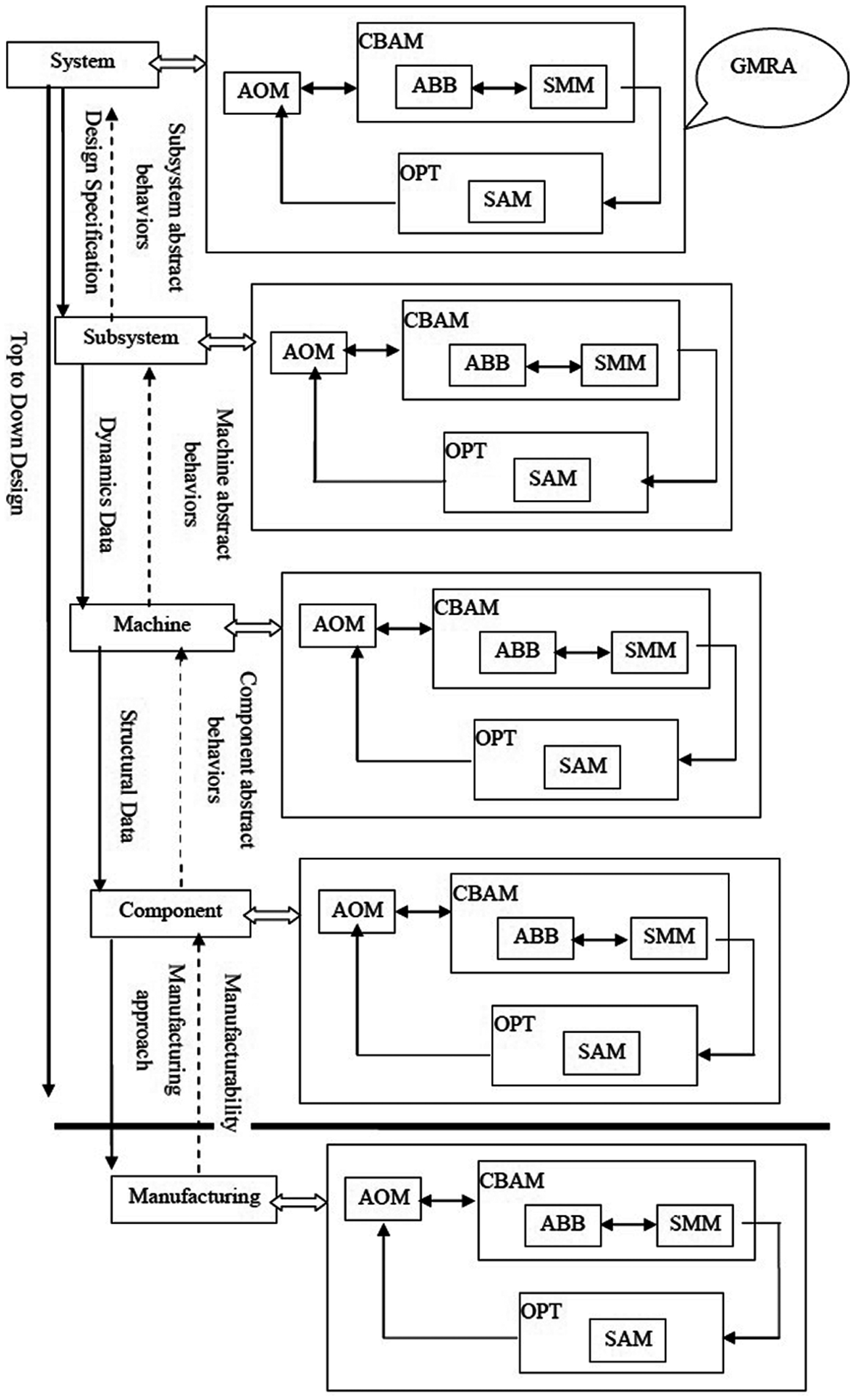
Holistic product design and analysis model (HPDA).
Modern railways are usually designed for high-speed and high-axle-load trains, which have become an attractive and effective means of transportation. Railway vehicle is a complex mechanical system. Because of its complexity, when designing a railway vehicle, a lot of analyses, such as dynamics analysis and FEA, are needed. Effective integration of the design and analysis models is very important in improving design performance. However, the existing approaches and models mainly concern FEA and are not suitable for dynamics analysis.
MRA proposed by Peaks et al. 3 is generic; it has been applied in a specific field for solder joint fatigue analysis but is limited in its usage scope. For a complicated multibody dynamic system design, plenty of dynamics analyses, FEAs, optimization and, even manufacturing-related analyses, such as manufacturability and costing are needed to be taken into account. So, the GMRA is established to present design process in each design phase by adding new modules, namely, Sensitivity Analysis Module (SAM) and Optimization Technology (OPT) module, into the MRA to support optimization in a design loop. The HPDA model is achieved by vertically integrating GMRAs at each design phase. HPDA represents a holistic approach to product design that comprises four levels: system, subsystem, machine and component levels. It describes the Top–Down design method very well and supports modular definition.
Each level has six modules, and for each level, there is a similar structure view but different presentations. The six modules include four modules from the MRA model and two extended modules: SAM and OPT.
At the system level, the design focuses on technology selection, system configuration or layout design of a mechanical product system based on social, economic, political, environmental and technical constraints. For a railway system, the type of power system, such as electric or internal combustion engines; configurations of the system, such as maximum running speed and rail width; and general design specifications can be generated from an optimal social–economic—technical system design. An Analyzable Object Model (AOM) is considered as a design scheme (configuration and specification) or master planning. The ABB presents transportation capability demanded, social and economic benefits, national or regional strategic roles and so on. The SMM is regarded as various social–economic–technical design evaluation models and tools. Context-Based Analysis Model (CBAM), in this phase, supplies an environment for designers and analysts, such as planning designers, feasibility and cost control analysts, to understand and discuss the design scheme. The SAM reflects what kind of conditions and factors could influence this design scheme and how strong the influence is. The OPT module indicates that according to the results of SAM, the design scheme, including functions and design methods, can be adjusted and optimized.
At this level, the main requirements and desired functions are considered, and normally a number of potential configurations are outlined. A case is represented in Figure 2.
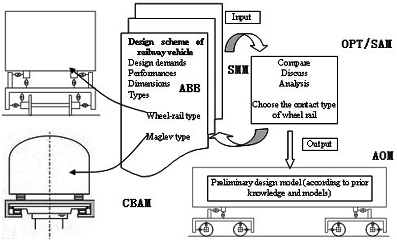
A case of system view for a railway vehicle design.
At the subsystem level, the model represents dynamics information of a mechanical product. From this model, the dynamics performance of the product can be designed and verified. For example, when a railway vehicle product is designed, the dynamics behaviors such as wheel unloading ratio, derailment coefficient, hunting stability, curving behavior and ride comfort will be investigated. The simulation of velocity, acceleration and forces on each part can be achieved simultaneously. Figure 3 illustrates the design process at the subsystem level.
A case of a subsystem view for the railway vehicle design.
According to the design scheme from the system-level view and prior design knowledge of railway vehicle, the preliminary design model as input for subsystem-level view can be obtained from the output of the system-level view. It mainly concerns CAD models and design demands. Obviously, the preliminary design model is also considered as the AOM. The ABB describes the railway vehicle’s topological structure for dynamics, including assembly information, links and constraints. The CAE model can be achieved by conjunction of the AOM and ABB. CBAM is a simulation environment to accommodate the AOM and ABB to support the SMM (to solve and simulate). The SMM supports an in-house developed package to solve the analysis equations or supplies the interface for the commercial software, such as ADAMS and SIMPACK, to simulate. Most optimization algorithms require the derivatives of the objective and constraint functions with respect to design variables that are indicated in the CBAM. So, the SAM is a bridge between design analysis and design optimization. The OPT defines a set of methods to support the optimization and data communication back to the design model and to drive the design model to adjust and modify.
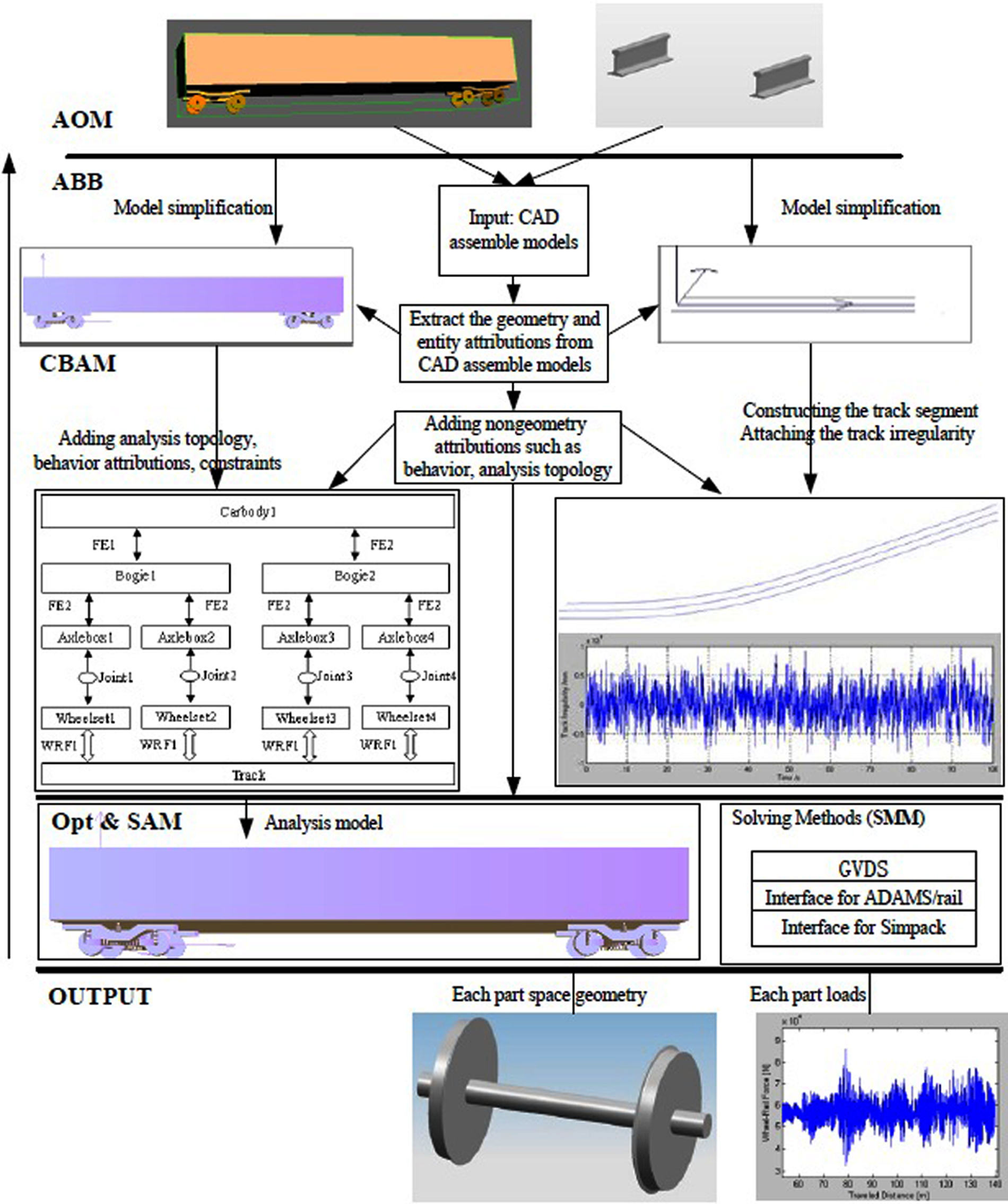
At the machine level, the CAD models with forces and constraints of each part are considered as the AOM; the strength and fatigue information of mechanical product could be obtained. According to practical analysis demands, CAD models must be simplified and reconstructed to produce mesh models with geometry features in ABB. The SMM, CBAM, SAM and OPT have similar definitions as in the case of the subsystem-level view. A case of railway vehicle for the machine-level view is used to illustrate the process in Figure 4.
A case of a machine-level view of the railway vehicle design.
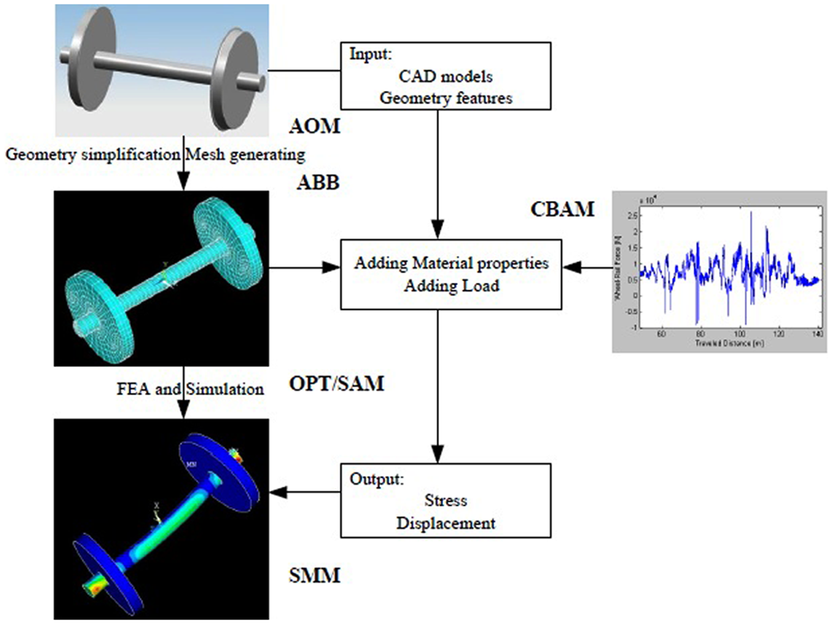
At the component level, structural and geometric information of mechanical parts could be selected and defined, as shown in Figure 5. The SMM could be for FEA or fatigue analysis and SAM and OPT could be for cross-section design and optimization.
Component-level view for practical structure design.
At the same time, if the focus is extended to manufacturing, the proposed model can be easily extended to manufacturing process, even the whole product life cycle, by including life cycle cost modeling, customer relation modeling, supply chain modeling and maintainability modeling.
GMRA and an example
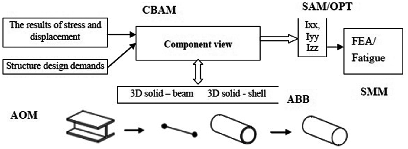
Here, a subsystem-level view of a railway vehicle design is demonstrated. The MRA is extended by adding a SAM and an optimization model to construct the GMRA, which is suitable for a complicated multibody system dynamics design, analysis and optimization. The proposed GMRA is shown in Figure 6, in which APM, ABB, SMM and CBAM are also discussed in detail.
Generalized Multirepresentation Architecture (GMRA) for design optimization.
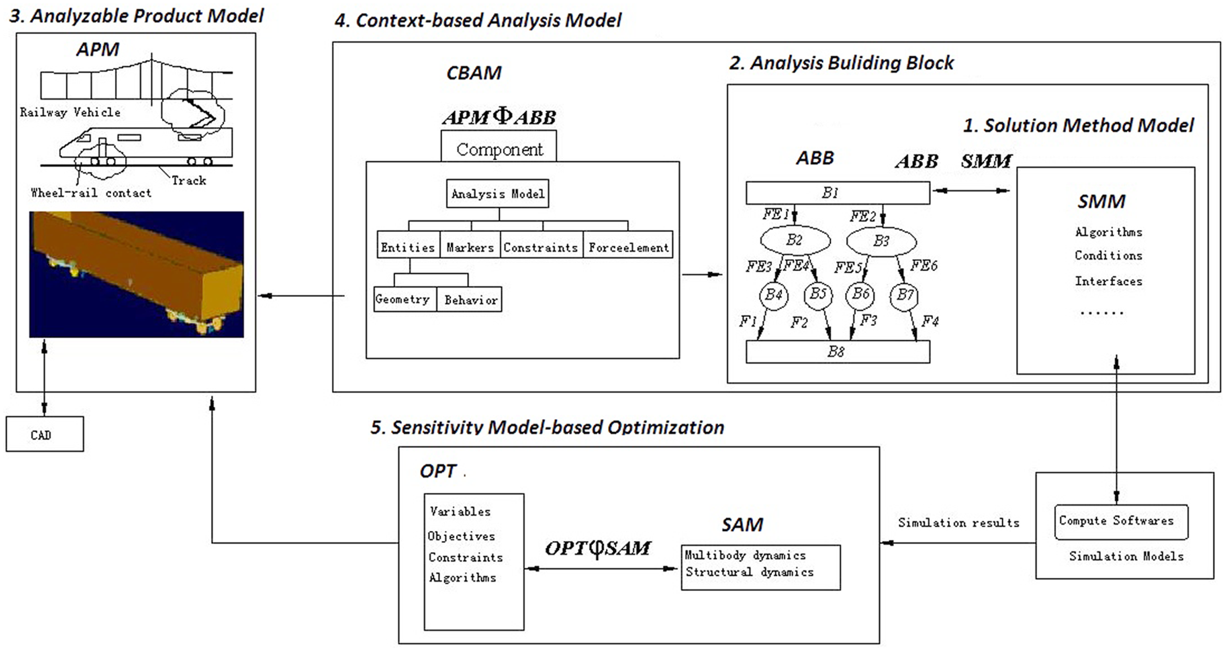
Traditional CAD models only include low-level information (geometry, entity, features of a product). In order to reduce the gaps between CAD and CAE models, the CAD models are enriched and attached with more and more attributions. As is common knowledge, a railway vehicle is a complicated mechanical system. So, in its subsystem-level view, APM (an instance of AOM) must present more complicated information, not only the geometric and entity information but also the attributes for dynamics analysis, such as assembly and structural topology. The topological structure of a railway vehicle system is illustrated in Figure 7.
The classical topological structure of a railway vehicle.
The APM effectively represents the design model. The design-oriented attributes are related to idealization attributes to support the information needs of dynamics analysis, such as parts, associated forces, force elements, constraints, parameters and optimization information.
The CBAM mainly relates to a particular design field such as what kind of analysis is needed. The analysis model is created in the CBAM through the combination of ABB and design–analysis association and the rules of the CBAM.
The ABB reconstructs the product dynamics topological structure, including assembly information, constraints and analysis conditions. Analogous to the design, it also includes analysis goals of wheel unloading ratio, derailment coefficient, critical velocity and so on. As for sensitivity analysis, it supplies a design variable set to be selected. It can be converted into a SMM.
The SMM presents a set of solution methods and supports external analysis tools (such as ADAMS and SIMPACK) in solving. As for this model, a solution method with a simulation prototype package is developed to compute the dynamics data, which has been verified in multibody dynamics analysis compared with ADAMS.
The SAM is a bridge between analysis and optimization design. It defines a generic expression template of first-order sensitivity analysis to associate the analysis results with the design parameters. It can describe how the design parameters are related to analysis parameters.
The OPT defines a set of methods to support the optimization, and send data back to the design model and drive the design model for adjustment and modification.
The GMRA with above modules can be mapped into an iterative design process of design–analysis–redesign based on STEP by EXPRESS and EXPRESS-G. It can ensure that the design and analysis parameters are appropriately related between design and analysis activities. EXPRESS is an object-oriented language. So, it could be used for describing the GMRA, as shown in Figures 8 and 9.
Simplified EXPRESS-G.
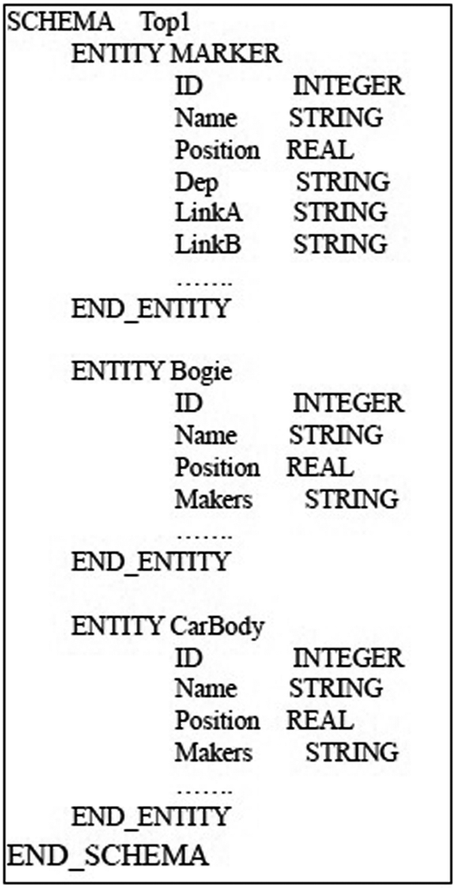
Simplified EXPRESS.
As an example, in Figure 9, the entity A is named “Bogie,” a moving part connecting vehicle body and the rail track. The entity B is named “carBody,” the vehicle body. Their linkage is described as “MARKER.”
Design and analysis package of railway vehicle based on GMRA
For proving the concept of the HPDA and GMRA, a design–analysis package of railway vehicle based on GMRA has been developed and named Generalized Vehicle Dynamics System (GVDS). 24 GMRA is presented by EXPRESS and EXPRESS-G based on STEP. EXPRESS is an object-oriented language; hence, the design and analysis package for railway vehicle must be developed by an object-oriented method. The bodies, constraints, force elements and forces of a multibody system could be defined as objects which have encapsulated their properties. So, a three-dimensional simulation environment (see Figure 10) named 3dWorld is established, and it mainly consists of 3dOjbect, Constraint, ForceElement, ForceTorque four parts (classes). The constraints, force elements and forces are associated with objects. The vehicle dynamics, wheel–rail contact geometry and forces are implemented in the 3dWorld, and it can be used to simulate the real behavior of a railway vehicle. The operators can simulate, analyze and evaluate the behaviors such as hunting stability, side comfort, curving behavior and so on of the vehicle.
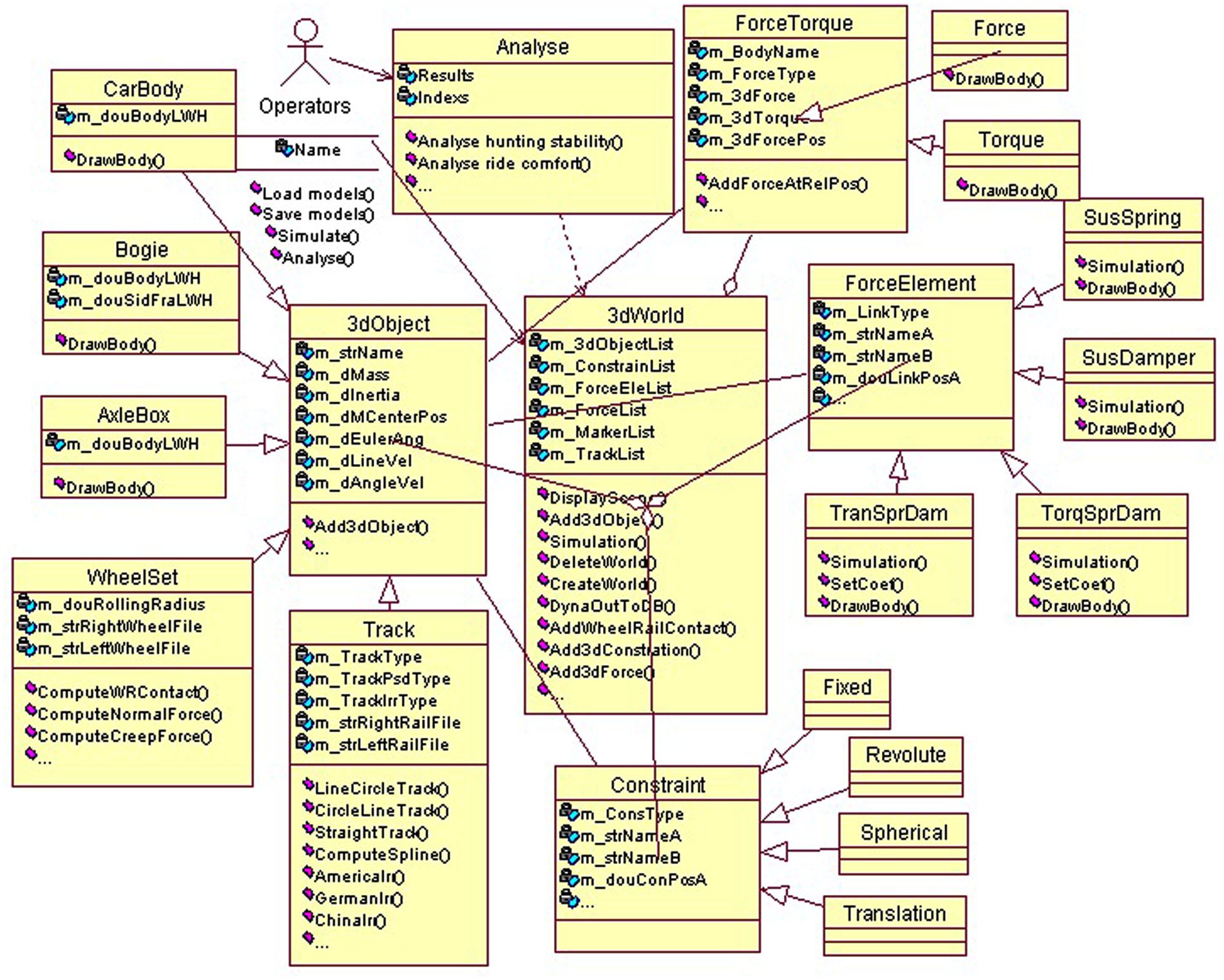
Class diagram of the analysis package.
At present, only the design-to-analysis process is considered in this article; the sensitivity analysis and optimization will be reported and discussed in the next phase. Therefore, GVDS mainly involves multibody system dynamics and wheel–rail contact theories that are special and difficult. The implementation of GVDS is described in the study by He et al., 24 and the reliability and effectiveness of GVDS is also proved.
Case study
To evaluate the feasibility of the proposed HPDA and GMRA, a case was studied in detail. The design process is represented in section “HPDA model.” According to the system-level view, design specifications and wheel–rail contact scheme of railway vehicle were obtained, and with a priori design knowledge and experience, a preliminary CAD model was achieved.
Wheel-set and railway vehicle system can be designed and assembled in CAD environment, such as UG and Pro/E. The design model from the CAD models based on STEP and associated with the dynamics attributes via EXPRESS are extracted and simplified to construct the APM of GMRA, as shown in Figure 11.
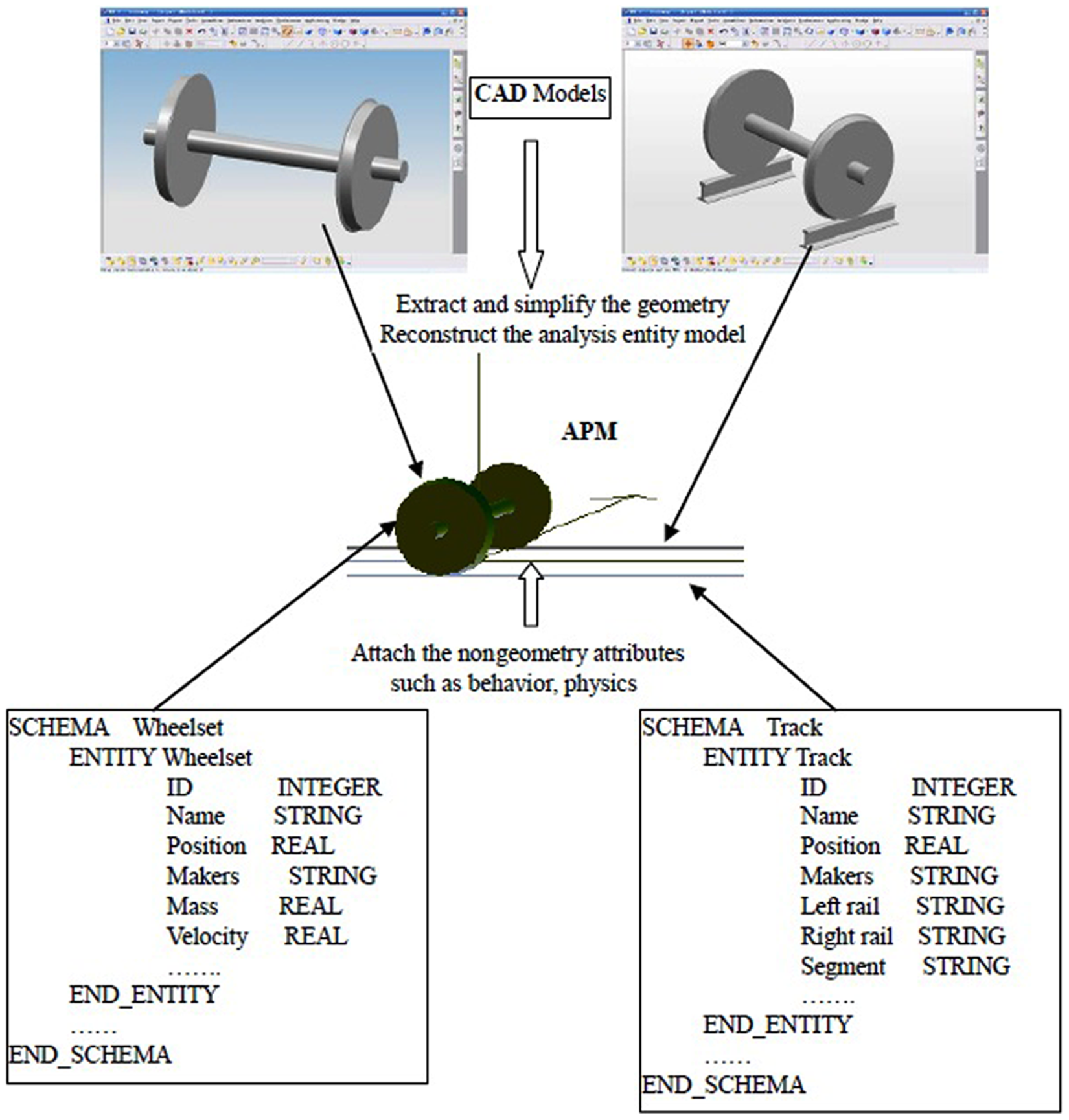
Mapping process of APM based on EXPRESS.
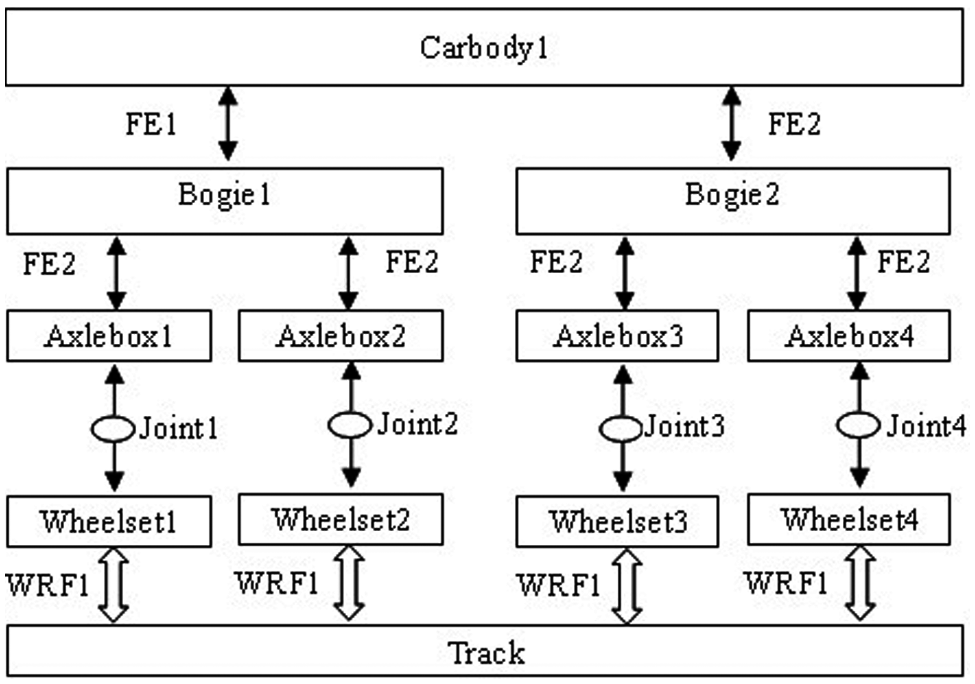
The ABB defines the track conditions, rail irregularity, constraint types, topology structure and so on. It can also be presented by EXPRESS-G, as shown in Figure 12.
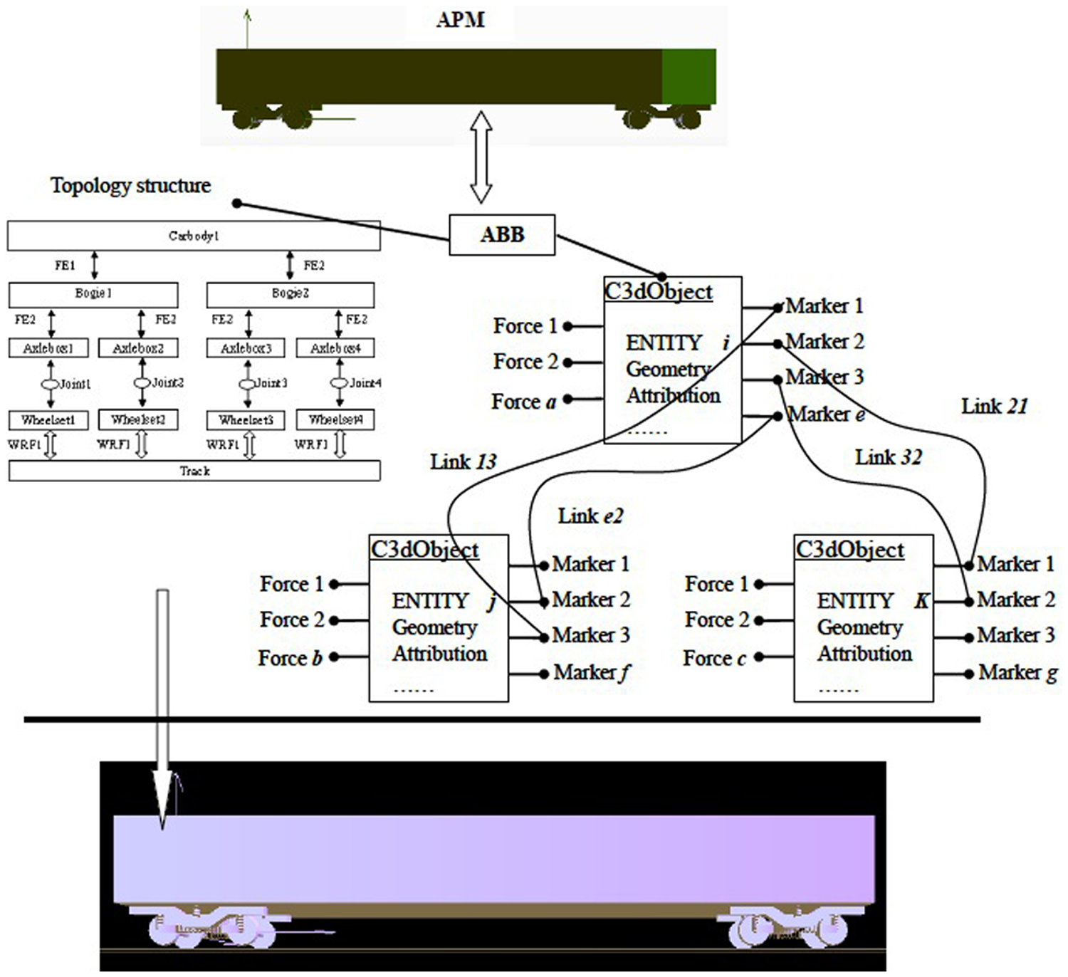
Mapping process of APM and ABB based on EXPRESS-G.
The solution method sets of the SMM are integrated into the simulation platform and supply interfaces for external analysis tools (ADAMS and SIMPACK) to solve. As for this model, a solution model has been developed to compute the dynamics performances, which are settled in CBAM. ABB and SMM components are illustrated in Figure 13.
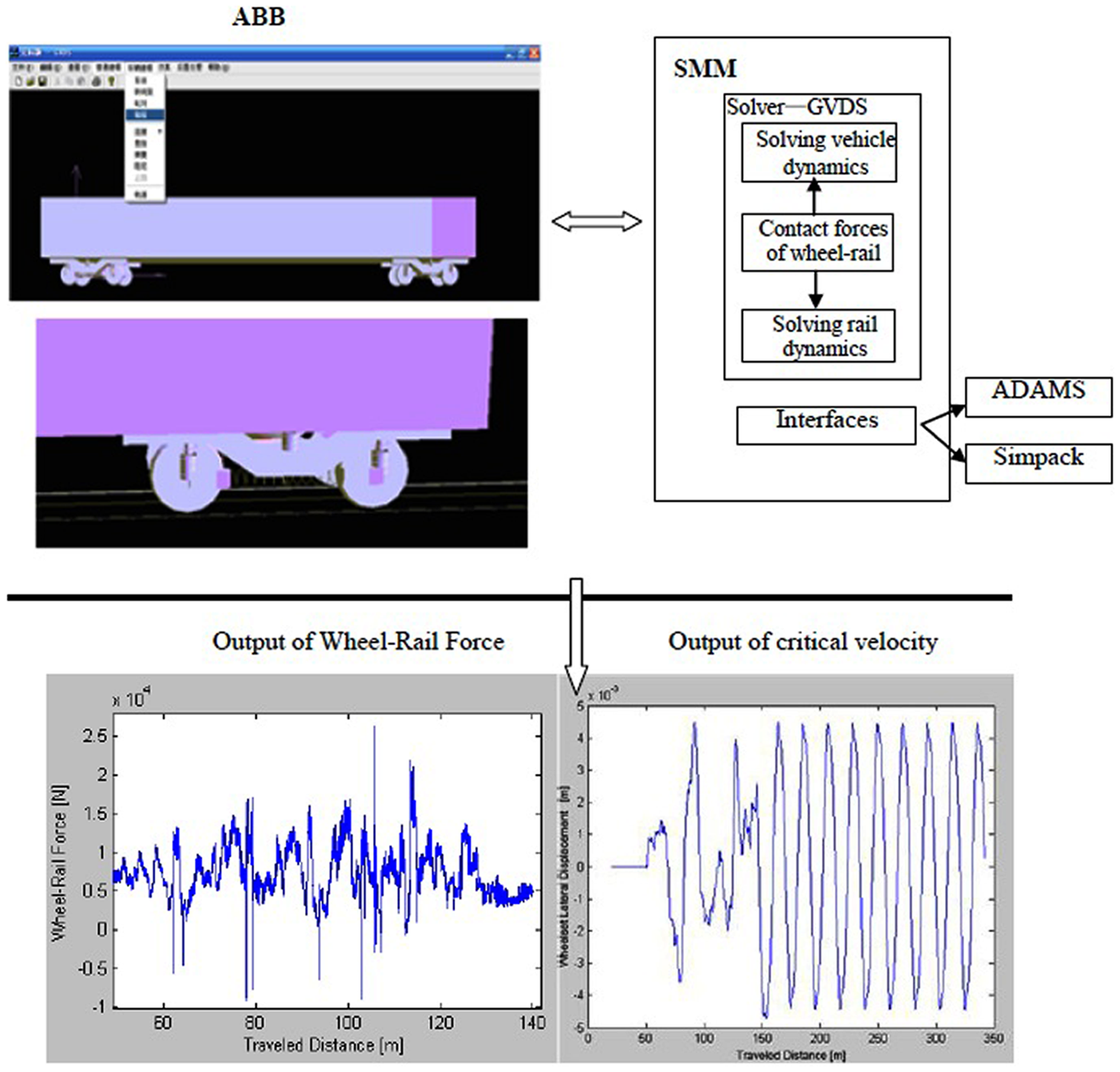
ABB to SMM.
Figure 14 gives more simulation results. For GMRA, the design to analysis integration process is merely considered, and the sensitivity analysis and optimization will be reported and discussed in next phase. Through the subsystem-level design, the geometric dimensions and forces of each part of a railway vehicle are obtained, and these results are necessary conditions for next machine (product) design.
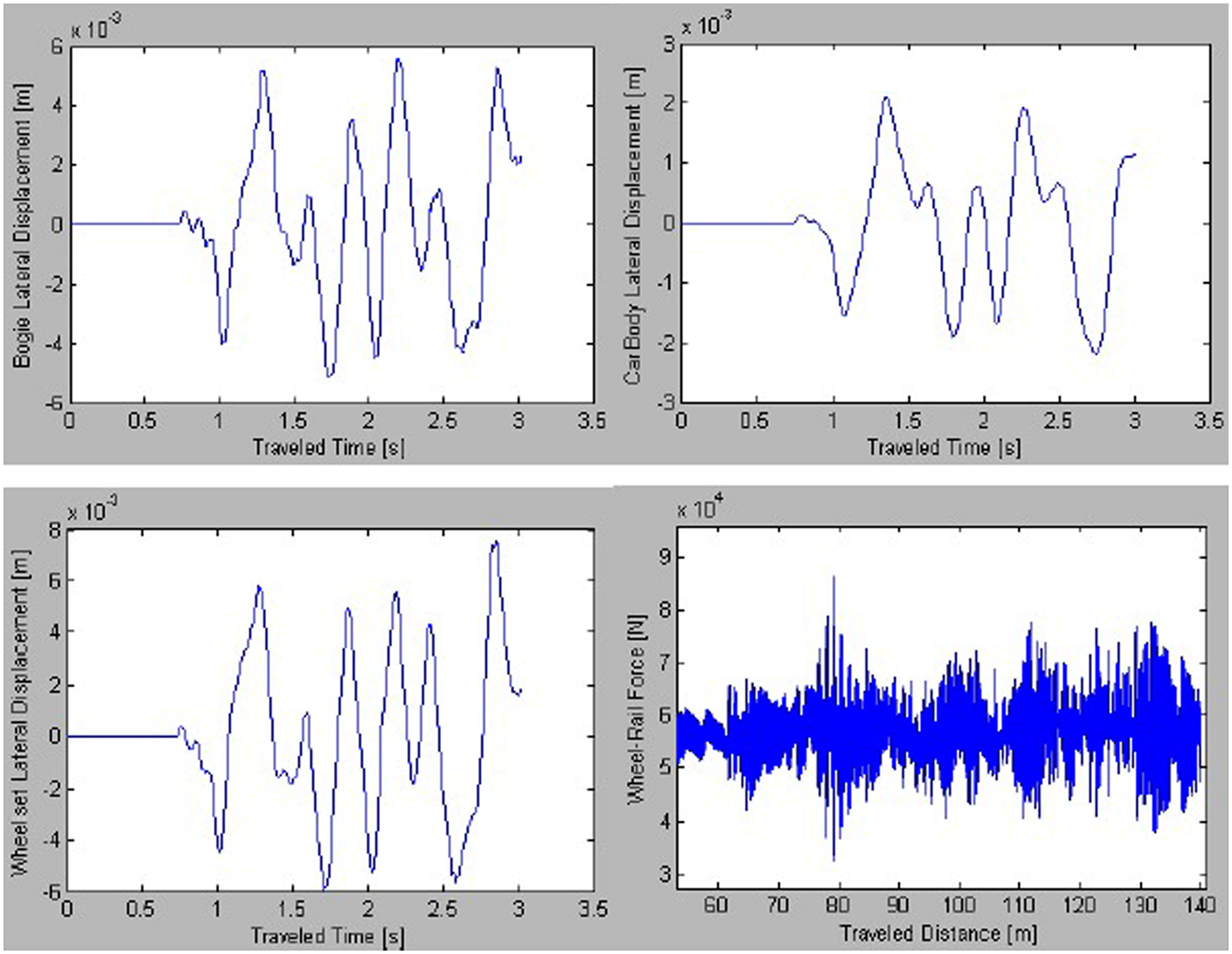
Model analysis results.
Discussion
The MRA is a generic architecture for engineering design and analysis integration, but it is not enough for analysis of a complex mechanical system. For a general complex mechanical system, such as a railway vehicle, multibody system dynamics analysis and optimization needs to be urgently resolved. Therefore, some modifications and extensions to include new models (such as topology structure in ABB) are necessary to make it suitable for dynamics analysis, finite element–based stress analysis and others. Therefore, by adding new modules (SAM, OPT model) into the MRA to support design optimization within a design loop, the GMRA is established to support the “horizontal” integration in the design–analysis–optimization process in each design phase. By composing GMRAs in each design phase, the HPDA is developed to “vertically” integrate design information.
In this article, the feasibility and effectiveness of HPDA and GMRA are proved by a complicated railway vehicle design process. Hence, the HPDA and GMRA are applicable in other general multibody system designs.
Theoretically, the proposed model could be extended, but this article focuses on performance-based design analysis; further research in which Model-Based Definition (MBD) and annotations technology will be used will follow.
Conclusion
Traditional CAD and CAE integrations mainly consider CAD and FEA integration. There was no focus on multibody dynamics analysis of a mechanical product. However, before the FEA, the loads (forces) and constraint conditions for each part within a complex mechanical system must be obtained through dynamics design and analysis.
In this research, a framework of a HPDA model is developed to integrate the CAD and CAE, which includes not only FEA but also dynamics analysis and optimization, and to reduce the gap between engineering design and analysis by facilitating reuse of GMRA models. The GMRA can support design–analysis–redesign iterations and enhance engineering design and analysis interoperability. The case study on a railway vehicle system design has illustrated the feasibility and applicability of the proposed HPDA and GMRA in general mechanical product design. Based on the HPDA and GMRA, design automation, global optimization model, PLM-based design and so on will be further researched.
Footnotes
Funding
This work was supported by the National Natural Science Foundation of China (grant number 50975240), the Youth Fund of Sichuan Province (grant number 09ZQ026-003), the Fundamental Research Funds for the Central Universities (grant number SWJTU09ZT06) and the New Century Excellence Plan (grant number NCET-09-0665).