
Abstract
The primary causes of defects in planed timber surfaces have been identified to be cutting tool inaccuracy and forced vibration during the machining process. It is noted that the current mechanical methods used in the woodworking industry to improve surface finish quality have disadvantages that defeat their original attractiveness. This article describes a mechatronic approach used to compensate for cutting tool inaccuracy in wood planing via cutting tool trajectory modification. The approach is based on real-time measurement of the angular spindle position, coupled with periodic vertical displacements of the rotating spindle. A small-scale wood planing machine, which has an actively controlled spindle unit, has been designed for practical investigation of the technique. Experimental results show that the dynamic performance of wood planing machines, and hence the surface finish quality, can be improved via this approach.
Keywords
Introduction
The basic principle of the rotary wood machining process is such that the workpiece is fed against a rotating cutterhead as illustrated in Figure 1. The process is similar to metal milling, but the primary differences are that the feed speed and the cutting speed far exceed those of metal milling. The number of cutting knives on the cutterhead usually ranges from 4 to 20, and the cutting edges are mostly straight in contrast to the helical cutting edges used in metalworking. One of the most common rotary machining operations is wood planning.1,2
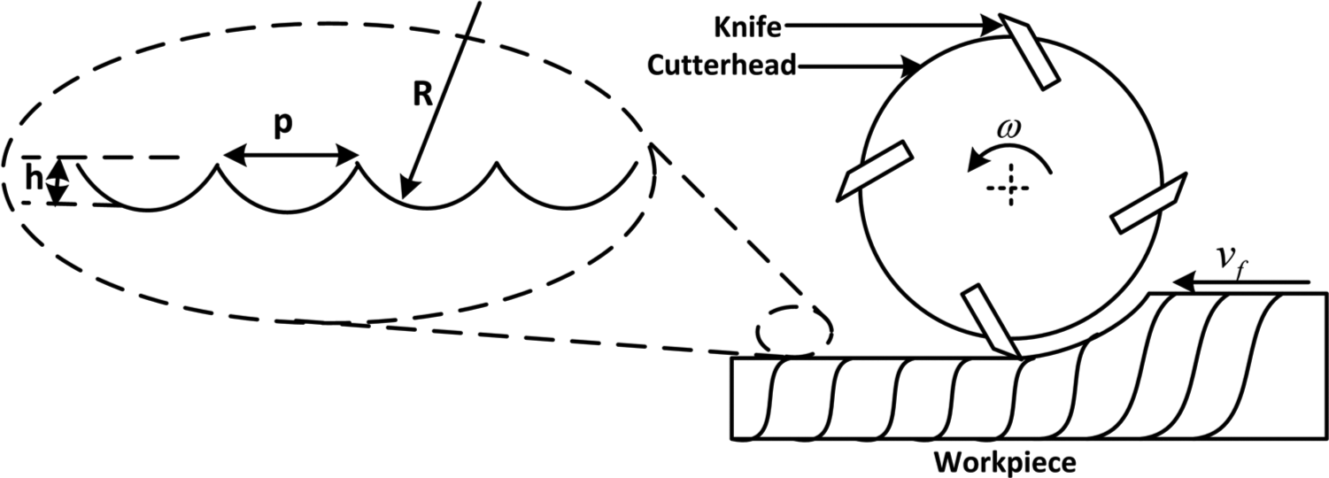
Principle of the rotary machining process.
Owing to the intermittent engagement of the cutters with the workpiece, a planed timber surface consists of waves known as cuttermarks. The uniformity of the cuttermarks is the main parameter used to determine the quality of the surface finish. Machining parameters are selected by the operators in order to produce the desired waviness pitch p (mm) and height h (mm). The theoretical pitch and height of cuttermarks are calculated using the following equations 2


where vf (mm/s) is the workpiece feed speed, ω (rad/s) is the cutterhead rotational speed, R (mm) is the radius of the cutter and N is the number of cutters.
It has been observed in practice that some factors, such as cutting tool inaccuracy and spindle vibration, introduce significant surface finish defects, causing the surface finish to deviate from the desired waviness pitch. Although surface defects can also be amplified by the type and condition of the timber material, they are primarily a function of the machine deficiencies. 3
The traditional mechanical solution to the problem of cutting tool inaccuracy in the woodworking industry is to apply a process known as jointing, which is used to true all the cutting edges to the same radius. 4 The disadvantage of jointing is that it leads to accelerated tool wear. This does not only increase the tooling cost, but it also increases the normal cutting forces generated during the machining process and hence increase in power consumption.3,4 Apart from the cutting tool inaccuracy, structural vibration is another major cause of defects in rotary wood planning.3,5 Vibration has been a major inhibitor to high-speed machining because its effects become more pronounced as the cutting speed increases. The focus of this article is on cutting tool inaccuracy compensation via real-time adjustments of the vertical cutterhead position. The study of the combined effects of both cutting tool inaccuracy and superimposed spindle vibration is a subject of future articles.
Review of related work
The quality of machined wood surfaces can either be improved through optimisation of machining parameters or modification of machine dynamic characteristics. In the first approach, models that predict the quantitative relationships between machining parameters (cutting speed and feed speed) and surface finish quality are used to select optimal machining parameters for obtaining a high quality surface finish.6,7 In the second approach, surface finish quality is improved through real-time modification of process kinematics (cutter-path optimisation)8–12 and active vibration control. 13
This first approach has been used to minimise surface roughness during milling of medium density fibreboard (MDF) in Gaitonde et al. 6 and Davim et al. 7 It is reported in both articles that the surface finish quality of milled MDF increases with an increase in cutting speed. Surface finish quality improvements through optimisation of the machining parameters is not suitable for cutting tool inaccuracy compensation in wood planing because the inaccuracy is owing to the geometry of the cutting tools. Moreover constant cutting speed and feed speed are required in order to obtain uniform cuttermarks. Therefore, real-time modification of the process kinematics approach is explored in this article.
The idea of improving the quality of planed wood surfaces through real-time adjustments of cutting tool trajectories was first postulated by Jackson. 3 This idea has since then been explored by a number of researchers. The first one is the introduction of additional horizontal cutterhead movement during the machining process.8–10 The objective of the horizontal cutterhead movement introduction is to produce a surface finish with reduced waviness heights.
A similar approach is reported elsewhere11,12 but a vertical cutterhead movement is introduced instead. Results show that this method also produces cuttermarks height below what is obtained from conventional machining by shaping the cuttermarks on the machined wood surface. The objective of the current research is not to produce cuttermarks with reduced heights, but to minimise the effects of uneven cutters.
Principle of the cutting tool inaccuracy compensation
Defects owing to cutting tool inaccuracy typically occur in multi-knife finish operations. It is a common occurrence for the cutting edges to have different radii owing to the difficulties in grinding and setting them to a very high level of precision. Even the use of the best available precision tools and techniques would still produce a total indicated run-out (TIR) within the range of 5–10 µm. 3 The TIR is the difference between the longest and the shortest cutter radii on the cutterhead. A TIR value of less than 1 µm will be required to produce an acceptable multi-knife finish, but this is not technically feasible at any reasonable price via mechanical methods. 2
The proposed technique for compensating for cutter inaccuracy is to adjust the cutterhead vertical position in such a way that all the cutter tips are at the same level when passing through their lowest positions. 14 The technique is described here.
Assuming there are N number of cutters on the cutterhead, each with radius R1, R2, .…. RN. One of the cutters is taken to be the reference. If the reference cutter has a radius of Rs, then the respective error of each cutter i, relative to the reference cutter, is given as

The idea is to displace the cutterhead vertically by a value of ei within an angular rotation where the ith cutter produces visible cuttermarks on the timber surface. The cutterhead is then moved downward outside this angular movement. The whole movement is depicted in Figure 2. The effect of the vertical displacement is that it changes the effective radius of each cutter to that of the reference cutter, thereby serving the same radius adjustment purpose as the mechanical jointing process. There are two sets of a priori information that are required to implement the vertical cutterhead pulse in real-time. The first are the static run-outs of the cutters and the other are the absolute angular positions of the cutterhead at the lowest point of each cutter.
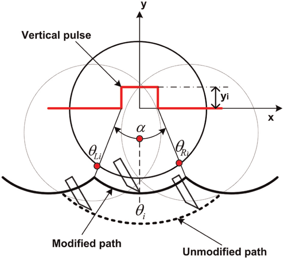
Principle of the cutting tool inaccuracy compensation.
There is a very short time window within which the vertical displacement pulse must take place. The pulse width is the time t required by the reference cutter to machine one cuttermark, which is expressed as follows 9


Taking the absolute angular position of the cutterhead at the lowest point of each cutter tip to be θ i , the vertical pulse must be synchronised with the rotation of the cutterhead, such that it is applied when the angular position of the cutterhead is at least between θ Li and θ Ri . Any displacement of the cutterhead outside this angle will not influence the surface profile because the cuttermark produced by the cutter outside this angle will be removed by either the subsequent cutter or the same cutter during subsequent revolution

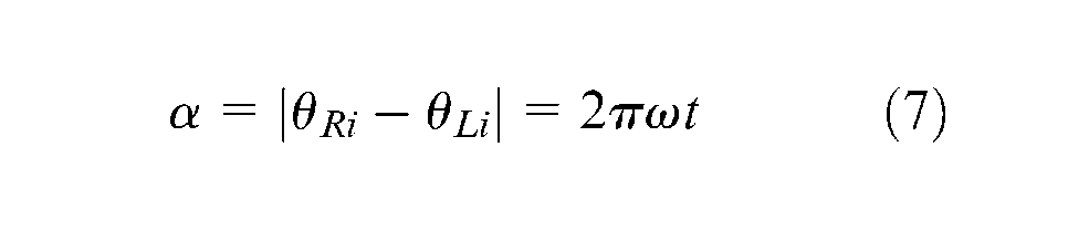
The angle between θ
Li
and θ
Ri
is very small (
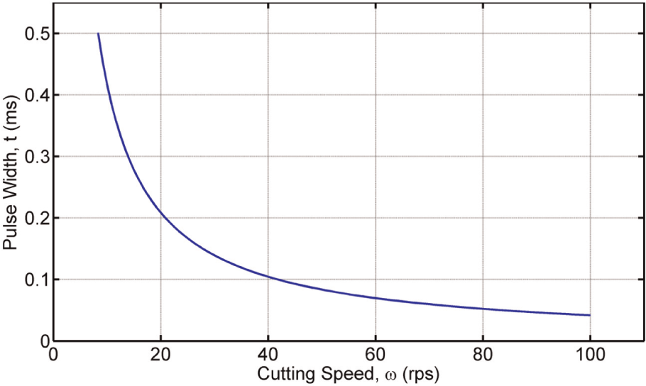
Relationship between pulse width and cutting speed.
The magnitude of the vertical pulse signal for each cutter is expressed as
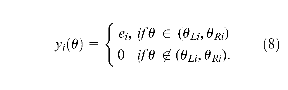
For practical purposes, the width of the vertical pulse could be increased beyond θ Li and θ Ri . This serves a dual purpose of accommodating any error in the measurement of θ i and also gives reasonable time for any transient responses to settle before the cutters reach the region where they produce visible cuttermarks on the workpiece.
Control system design
An appropriate control strategy that is capable of implementing the real-time tool trajectory adjustment is required. The linear quadratic Gaussian (LQG) tracking controller with integral action is chosen because it attempts to provide the best possible performance using the least amount of control effort. 15 The control objective is to drive the error between the actual spindle output and a desired reference path to zero. The LQG method is a model-based control approach, which requires a state-space mathematical model of the plant for the controller design. A system identification technique is used to obtain a model of the plant because it is based on observed input–output data from the system16,17 and it does not require the details of the physical principle guiding the behaviour of the system. The design of the LQG tracking controller typically involves computation of the feedback gains and the Kalman observer gains. 15
Optimal tracking controller design
Consider a linear time-invariant system described by the following discrete-time state-space equations


where A is the state matrix, B is the input matrix and C is the output matrix.
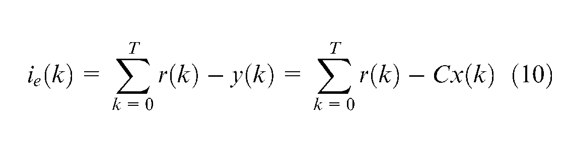
The requirement is to design a control system with a satisfactory transient response and the steady-state output of the plant should be equal to an arbitrary reference signal. This requirement can be greater achieved if the control law makes use of both the nominal state vector and the integral of the error between the reference and actual output. 18 Therefore, the integral of the error between the spindle position y(k), and the reference set-point value r(k), is used as an additional state variable to form an augmented state vector. The output of the integrator is given as
The augmented state vector

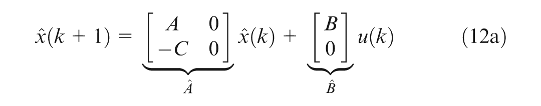
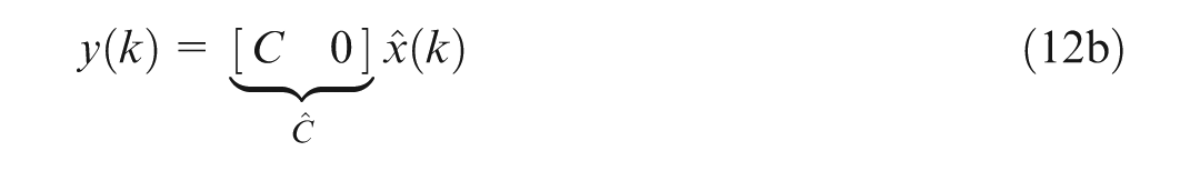
The state equation for the augmented system is given as 16
An optimal control law that includes feedback of both the nominal states variables and the added state variable is formulated as
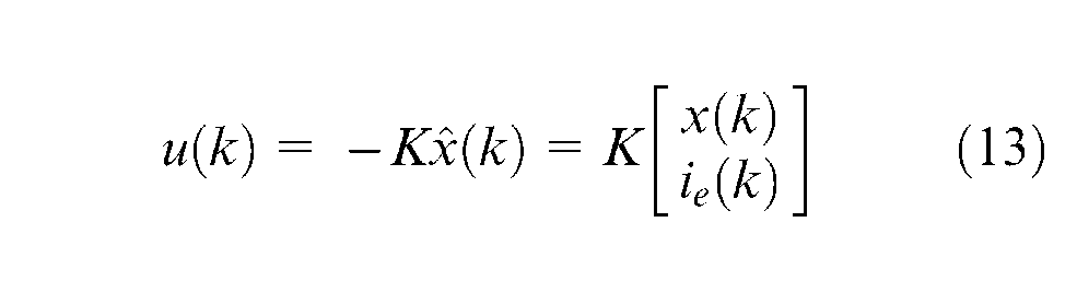
The gain K is calculated so that the control law minimises the objective function given by equation (14). The objective function defines the trade-off between tracking performance and control effort
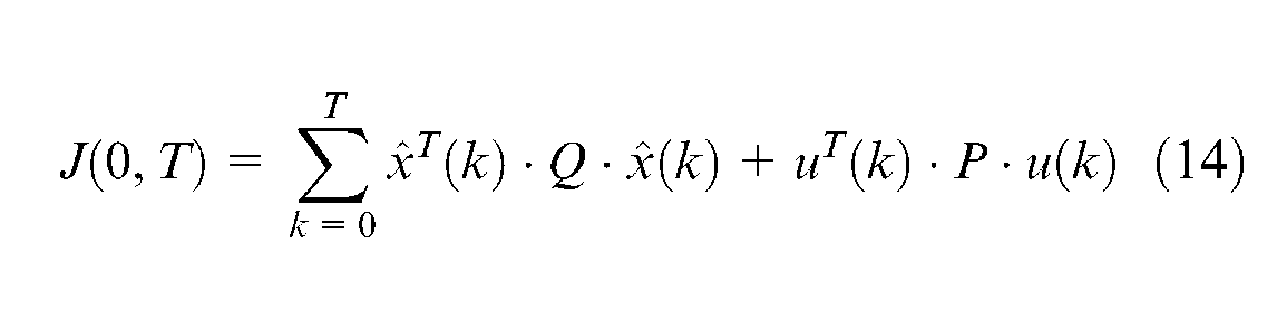
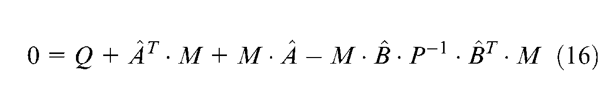
where Q is the state weighing matrix and P is the control cost matrix. The augmented state feedback gain matrix K is calculated from

where M is the solution to an algebraic Riccati equation, given by

The final control law is written as
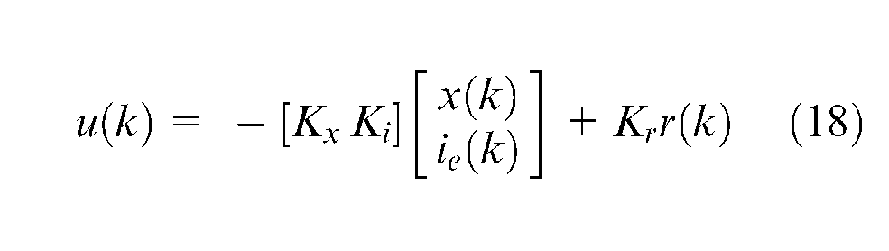
where Kx is the nominal state feedback gain, Ki is the steady-state error integral gain and Kr is the reference signal feedforward gain.
Optimal observer design (Kalman filter)
A full-state feedback cannot be used to design a control system because all the state variables cannot be realistically measured. A Kalman filter is required to estimate the state vector, based upon the output measurement y(k) and known input u(k). The goal of the Kalman filter is to provide an estimated state vector xe(k) so that the estimation error e(k) = x(k) – xe(k), is brought to zero in the steady state. The Kalman observer design is adapted from Tewari. 15 Consider a stochastic noisy plant that has the following discrete state-space representation


where v is the process noise vector, which may arise owing to modelling errors such as neglecting nonlinearities or higher frequency dynamics; z is the sensor measurement noise vector arising from sensor imperfections; and F is the stochastic noise coefficient matrix, which is also being estimated by the system identification algorithm.
The state equation of the Kalman filter is written as
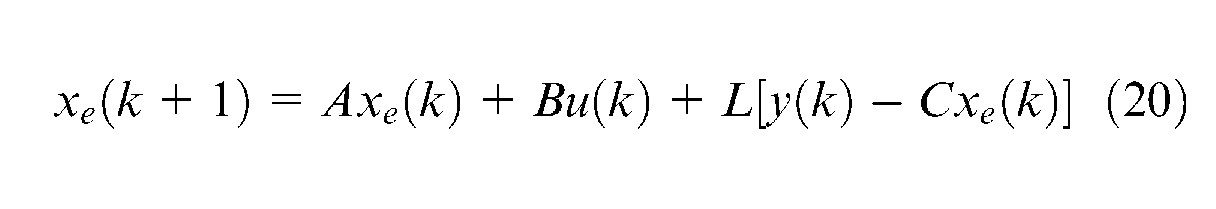
where L is the Kalman filter gain matrix. The Kalman filter is formed by minimising the covariance of the estimation error, Re = E[e(k), eT(k)]. The estimation covariance matrix Re can be evaluated by solving the following algebraic Riccati equation
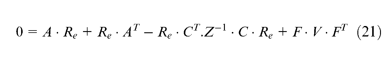
where A, F and C are the plant’s state coefficient matrices, V is the process noise spectral density matrix, and Z is the measurement noise spectral density matrix. The Kalman filter gain matrix is calculated as

Optimal LQG compensator design
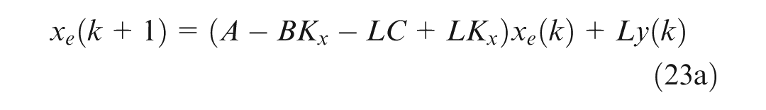
Having used the so-called principle of separation to design the optimal tracking controller and the Kalman filter, the two are combined to form an optimal compensator for the plant. The final state-space realisation of the optimal compensator for tracking a reference signal is given by

The schematic diagram of the LQG tracking controller is shown in Figure 4.
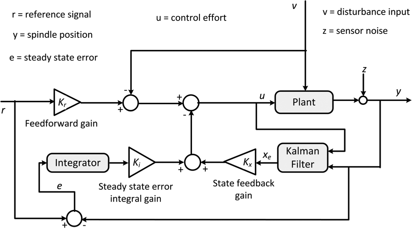
Structure of LQG tracking controller with integral action.
The feedforward gain, Kr, the controller weighting matrices, Q and P, and the Kalman filter’s spectral noise densities, V and Z, are the tuneable design parameters for the LQG tracking compensator. Hence, the desired closed-loop system’s performance is obtained by selecting suitable values of Kr, Q, P, V and Z. The compensator is designed using the lqg function in MATLAB Control System Toolbox and the overall control system is designed in Simulink.
Test rig configuration
An actively controlled wood planing machine (Figure 5) has been developed in order to carry out preliminary investigations into the different techniques that can be used to improve the performance of industrial wood planing machines.
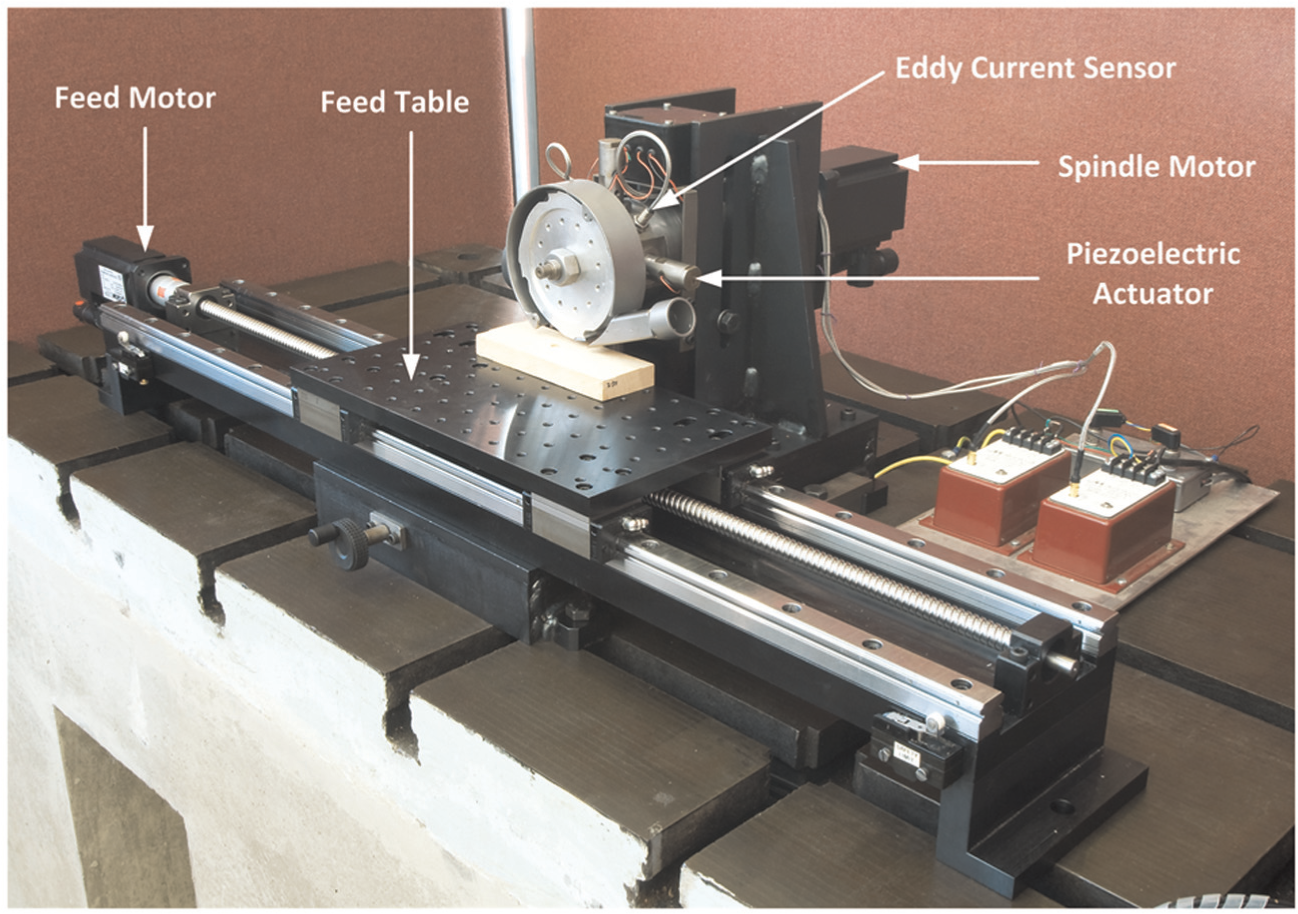
Actively controlled wood planing machine.
The spindle of the test facility is instrumented with two non-contact eddy current sensors and four piezoelectric actuators for actively controlling the spindle in the plane perpendicular to its rotational axis. The actuators are capable of moving the spindle by a peak-to-peak amplitude of 36 µm. The spindle is also equipped with a rotary encoder for measuring its angular position so that the vertical cutterhead movement can be synchronised with the cutter positions. The sensors are aligned with the actuators in the axial direction but rotated by 45° with respect to the actuators as shown in Figure 6. It is, therefore, necessary to transform the eddy sensor readings from the sensors coordinate system to the actuators coordinate system (xa, ya).
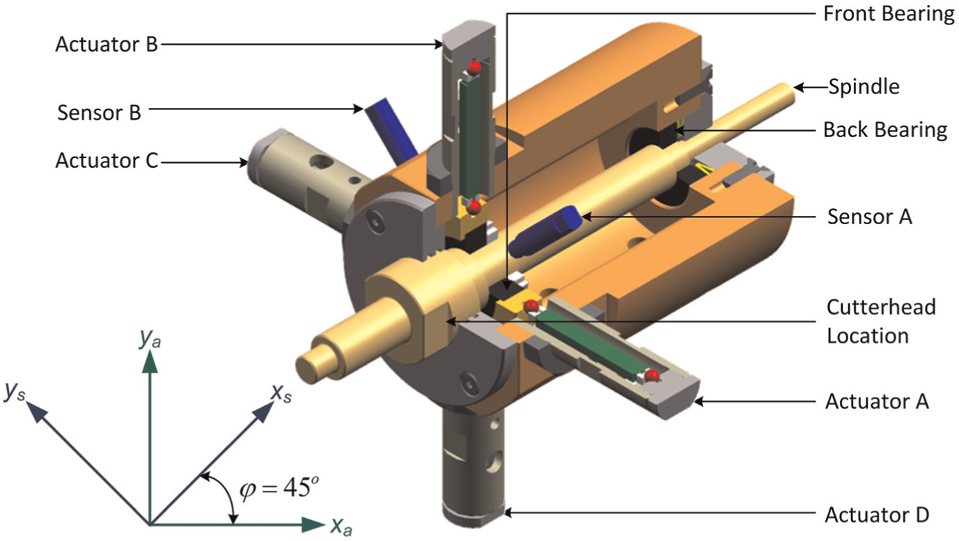
Actuators and sensors arrangement on the smart spindle unit.
Experimental tests and results
A real-time rapid prototyping environment from MathWorks known as xPC Target is used to control the wood planing machine. The xPC Target enables direct execution of Simulink and Stateflow models on a control computer for real-time testing. The xPC Target control machine is equipped with a data acquisition board (Humusoft MF614) through which it takes spindle orbit and angle of rotation data from the planing machine, and also applies control signals to the actuators. The xPC Target also provides an interface for real-time signal monitoring, parameter tuning and data logging from the control machine into the development machine. The control and development machines, which have been assigned static IP addresses, communicate via the Transmission Control Protocol/Internet Protocol (TCP/IP). The real-time testing environment is shown in Figure 7.
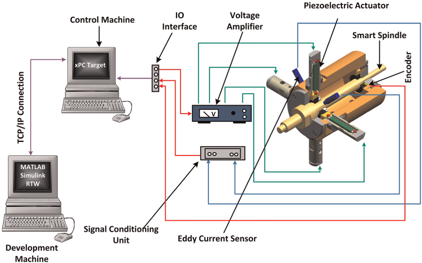
Schematic of the active wood machining control environment.
The eddy current sensors provide the spindle position feedback and the control effort generated by the controller is used to drive the piezoelectric actuators through the voltage amplifiers. The reference signal is generated based on real-time measurement of the spindle angular position through the rotary encoder. The encoder generates 2000 counts per revolution and an index pulse once every revolution. Although the rotary encoder gives relative positions, the index pulse is used to establish a zero reference (absolute) position of the spindle.
Real-time controller performance testing – engineering test
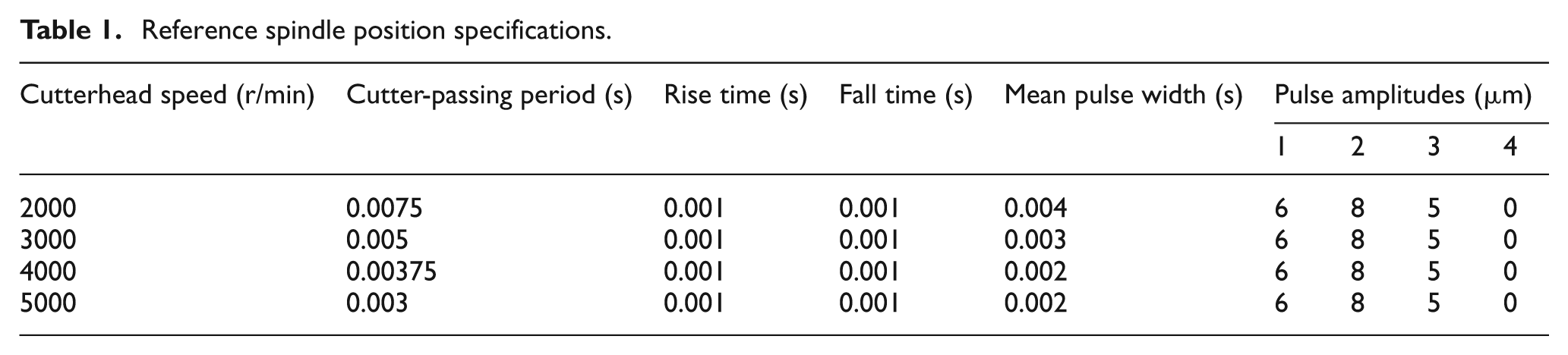
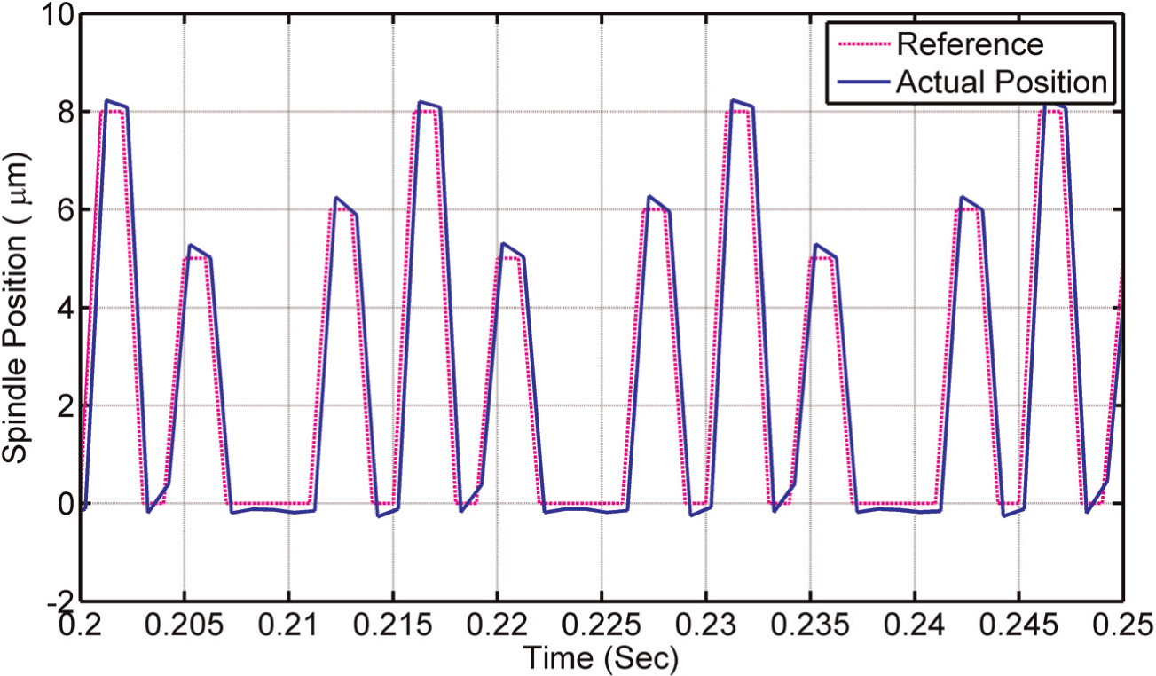
In order to determine the performance of the controller, the cutterhead was rotated at different speeds and the spindle was made to track arbitrary reference signals. Trapezoidal pulse (Figure 8) trains were used instead of the rectangular pulses that would be generated from equation (8) in order to take into account the response characteristics of the actuators (response time). The specifications of the pulse trains are presented in Table 1. The pulse trains are the ones that would be required to compensate for inaccuracy in a four-knife cutterhead having three proud cutters with static run-outs of 6 µm, 8 µm and 5 µm, respectively. The comparisons between the reference spindle position and the actual spindle position at the speed of 4000 r/min is shown in Figure 9. The sampling frequency of the system is 2000 Hz. The cutter-passing period is calculated from
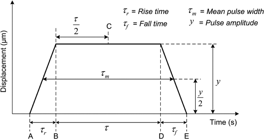
Trapezoidal pulse.
Reference spindle position specifications.
Tracking response of the spindle rotating at 4000 r/min.

Conventionally, the performance characteristics of reference tracking controllers are measured using the transient response parameters (rise time, overshoot and settling time) and the steady-state error. However, these parameters are not considered to be the most suitable in this work. Instead, the performance criterion is chosen based on the objective of the active machining system, which is to keep the spindle at the desired vertical positions when the cutters are within the angular positions where they produce visible cuttermarks on the workpiece. The positions of the spindle outside these regions do not have any effect on the surface finish. Therefore, the average percentage error between the reference positions and the actual positions of the spindle at the midpoints of the reference pulses (point C in Figure 8) is used to determine the performance of the controller. The efficiencies of the controller for the cutting tool inaccuracy compensation are shown in Table 2.
Controller efficiencies for cutting tool inaccuracy compensation.
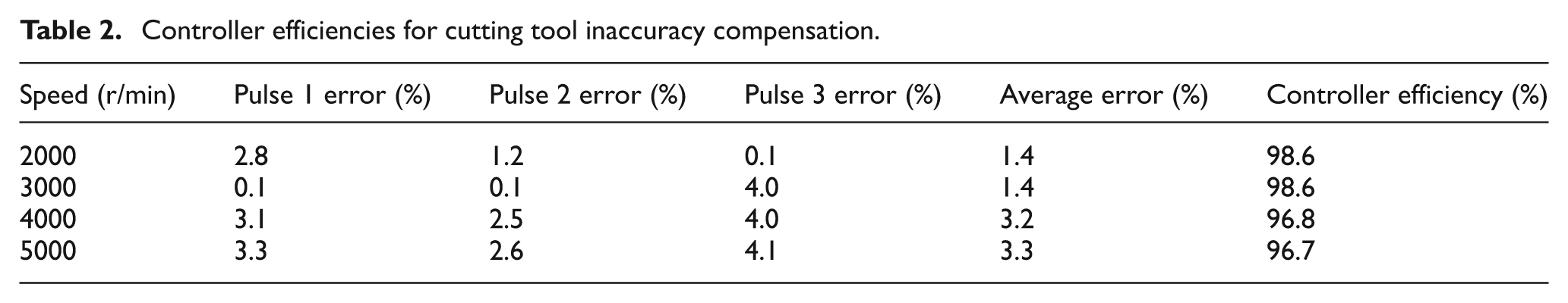

If the effects of other factors that could affect the surface quality of the machined workpiece (timber material properties, cutter geometry) are neglected, then it could be concluded that the enhanced dynamic performance of the spindle would automatically lead to improved surface quality.
Real-time controller performance testing – cutting test
As mentioned earlier, the static run-outs and the positions of the cutter are required to implement the proposed vertical cutterhead displacement technique. The static run-outs are measured while the cutterhead is mounted on the spindle in order to eliminate the effects of any misalignments between the centre of the cutterhead and the spindle centre. One of the cutters is taken to be the reference cutter. The cutterhead is rotated by hand on to a dial test indicator (DTI) until the highest point is registered on the reference cutter (maximum DTI reading). The DTI is then set to zero at this point. The run-outs of the other cutters are then measured in a similar way, relative to the reference cutter. The angular position of each cutter is also predetermined using the rotary encoder mounted on the spindle.
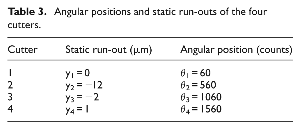
In order to evaluate the effects of the cutterhead displacement on the surface finish, a four-knife cutterhead with nominal diameter of 120 mm was mounted on the spindle. The cutters were numbered from one to four in the clockwise direction. The measured static run-outs and the angular positions of the cutters at their lowest points are given in Table 3. According to the measurements, the TIR of the cutterhead is about 13 µm.
Angular positions and static run-outs of the four cutters.
A steamed beech wood sample was machined without any compensation at the cutting speed of 1000 r/min and feed speed of 133 mm/s. These parameters were chosen to produce a 2 mm waviness pitch. The surface profile (Figure 10) was measured using the Alicona InfiniteFocus instrument.
Four-knife cutting test machined without compensation.
As seen in Figure 10, the surface profile is a three-knife finish because there are approximately three cuttermarks in one cutterhead revolution (8 mm timber length). The three-knife finish is owing to the 13 µm TIR of the cutterhead.3,14 The cuttermarks produced by cutter two have been completely removed by the other longer cutters. Although there are some variable differences in the heights of the corresponding cuttermarks from one revolution to the other, the overall waviness pattern is in close agreement with the static run-out measurements.
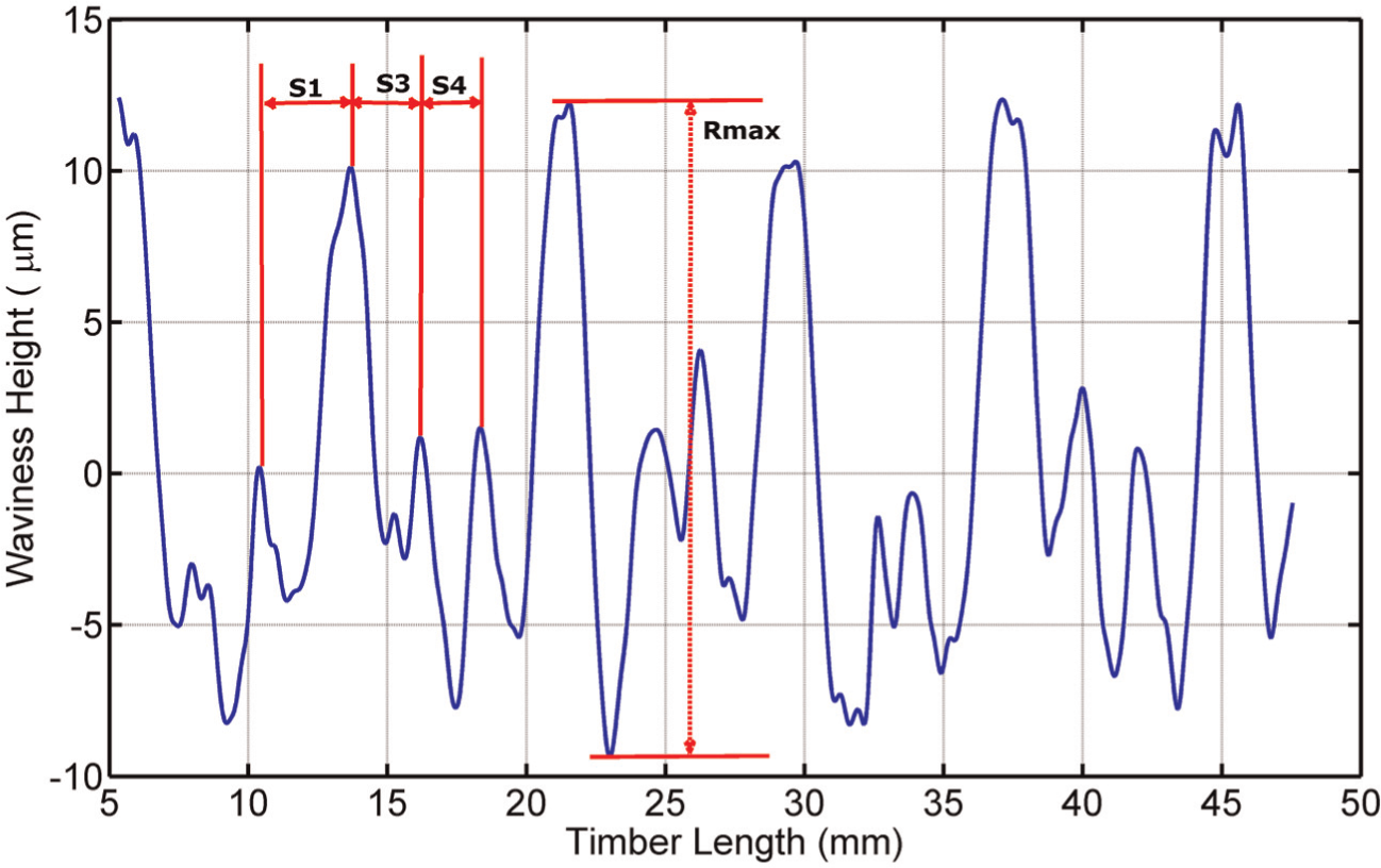
In order to compensate for the cutting tool inaccuracy, the cutterhead was displaced according to the static run-out measurements. Cutters two and three were displaced downward by 12 µm and 2 µm, respectively, and cutter four was displaced upward by 1 µm. The surface profiles obtained at cutting speeds of 1000 r/min and 4000 r/min are shown in Figures 11 and 12, respectively.

Four-knife cutting test machined with compensation at 1000 r/min.
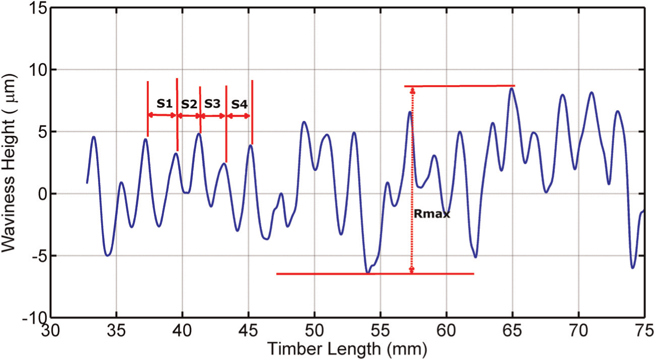
Four-knife cutting test machined with compensation at 4000 r/min.
Although there are still visible cuttermark height variations in the compensated surface profiles, the scales are much less than that of the uncompensated finish. This is evident in the maximum peak to valley heights of the profiles (Rmax). Also, the surface profiles are clearly four-knife finishes compared with the three-knife finish seen in Figure 10. The standard deviation of the widths of the cuttermarks within a selected sample length (three cutterhead revolutions) is used as the quality assessment parameter. The standard deviation is calculated as
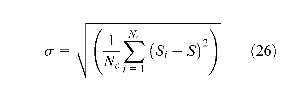
where Nc is the number of cuttermarks (four cutters × three revolutions),
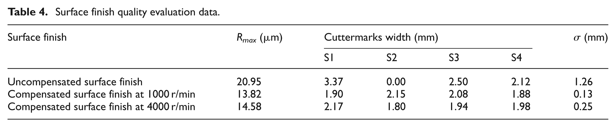
A low standard deviation indicates that the cuttermarks are more uniform and their widths are close to the desired waviness pitch of 2 mm. Therefore, the lower the standard deviation, the higher the quality of the surface finish. The surface finish quality evaluation data for the surface profiles are shown in Table 4. The standard deviations of the widths of the cuttermarks for the compensated surface finishes are much lower than that of the uncompensated finish. Based on these values, the compensated surface finishes have higher quality ratings than the uncompensated finish.
Surface finish quality evaluation data.
Conclusion
This article describes a new approach used to compensate for the effects of cutting tool inaccuracy in rotary wood planing. The technique is based on real-time periodic adjustments of the tool trajectory. Experimental tests have been performed on a mechatronic wood planing machine in order to evaluate its dynamic performance and also determine the effectiveness of the cutterhead displacements technique in improving the quality of the surface finish. The results show that the control strategy is capable of improving the dynamic performance of the machine and hence the quality of the surface finish. The direct benefits of this technique compared with the jointing process are lower tooling costs and higher machine performance.
The effectiveness of the proposed machining method would depend on a number of factors, such as the precision and accuracy of the static cutter run-outs and angular positions measurements. Also, the current design of the test rig has its limitations, which can prevent its industrial deployment. The main problem is that a relatively large cutterhead mass would need to be controlled by the actuators. Alternative design concepts are being pursued. Further work will also be done in order to compensate for the combined effects of cutting tool inaccuracy and forced spindle vibrations.
Footnotes
Appendix
Funding
This work was supported by the Engineering and Physical Science Research Council Centre for Innovative Manufacturing in Intelligent Automation at Loughborough University, UK.