
Abstract
A fuzzy anti-windup compensator is proposed and applied to the embedded cylindrical-array magnetic actuator to ensure the superior performance of spindle position regulation for milling machines under actuator saturation. Since embedded cylindrical-array magnetic actuator is a type of active magnetic bearing, the supplied coil current and the induced magnetic force are both limited by the maximum current and power output of the active magnetic bearing and the associated amplifier. Once the magnetic actuator is saturated, the required control input cannot be realized by an embedded cylindrical-array magnetic actuator and may lead to drastic tremble of the spindle position. In this work, an anti-windup compensator, based on a fuzzy logic algorithm, is therefore proposed to rectify the control input to an embedded cylindrical-array magnetic actuator. By employing commercial software, MATLAB/Simulink, and signal processing interface, Module DS1104 by dSPACE, the efficacy of the fuzzy anti-windup compensation is practically verified by intensive experiments.
Introduction
Windup generally refers to the saturation phenomenon of actuators, i.e. the magnitude or rate of magnitude of actuator output is limited by an upper bound. Consequently, the required control input cannot be realized by the actuator as long as the magnitude of required control input exceeds the saturation level of the associated actuator.1–3 Generally speaking, there are two approaches that can be adopted to avoid actuator saturation. The first approach is to take the limit of actuator output into consideration of controller design directly.4,5 The controller is expected to ensure the required performance specifications under the saturation constraint of actuator output. However, the controller design becomes complex or hard to be realized for practical applications. The alternative approach, referred to as anti-windup (AW) compensation in this article, is to separate the prevention of windup from the controller design.6,7 At first, the controller, without any constraint on the actuator, is synthesized to meet the required performance specifications. After the controller has been synthesized, the AW compensator is additionally included to ensure the stability and performance specifications under constraint of the actuator output. Such a technique is practically significant to provide a simple, intuitive and efficient way of solving actuator windup problems.
The general concept of AW compensation is depicted in Figure 1. 8 The “unconstrained controller” is referred to as the controller, which is initially synthesized under no limitation of actuator output: magnitude or rate of magnitude. The AW compensator output can be either the constrained or unconstrained control input and defined as
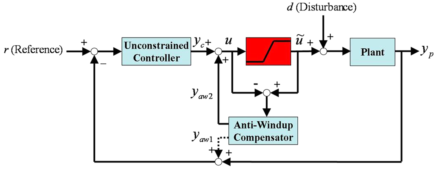
General schematic diagram of AW compensation.
where
Over the last decade, numerous systematic algorithms have been reported on AW design, such as robustness control,9–12 linear matrix inequalities (LMIs)13–15 and fuzzy logic algorithm.16–18 Most of the LMI-based approaches are based on the optimization of either a stability domain15,19 or a non-linear
Though the AW technology has been applied to various fields, for example, aeronautic/spatial problems,20,24 mechanical engineering,25,26 nuclear fusion,27,28 telecommunication networks29,30 and hard disk/motor control.31,32 However, the study on the windup of an active magnetic bearing (AMB)33–35 has not been addressed much. Besides, for a general AW compensation (see Figure 1), the proposed compensative action is engaged only right after windup has already occurred. Therefore, for high-speed rotary machines, e.g. high-speed milling, since the cutting dynamics sometimes varies drastically in a very short period of time, the actuator might not be able to instantly follow up. In this work, a fuzzy AW compensator is proposed and applied to the embedded cylindrical-array magnetic actuator (ECAMA) 33 to ensure superior performance of spindle position regulation under actuator windup. Though various strategies against windup have been proposed by the other works, the AW compensative actions are all engaged only after windup has already occurred. Therefore, the actuators by other works are not able to instantly follow up to suppress windup for the high-speed rotary dynamics of the spindle. In this work, the AW compensator is designed to be able to prevent the actuator saturation beforehand (i.e. prior to the occurrence of windup). Experimental simulations on realistic milling are presented to verify the efficacy of the proposed fuzzy AW compensator.
Modeling of spindle dynamics
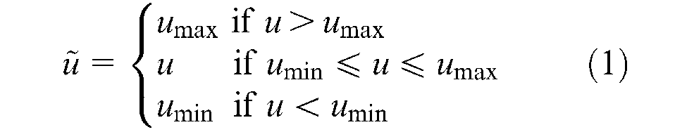
The ECAMA depicted in Figure 2 has been designed and verified by authors for high-speed milling applications. 33 By tuning the supplied current to the coil at ECAMA, spindle position deviation can be regulated by the induced magnetic force. Since the maximum supplied coil current and the induced magnetic force are both limited by the extrema of the ECAMA, the windup phenomenon takes place once the required control input exceeds the upper limit of the ECAMA or its power amplifiers. That is, if the required magnetic force is more than the upper limit that the ECAMA can generate, the preset control law will not be applicable any more. Hence, tremble of the spindle position takes place and may become drastic.
ECAMA and spindle: (a) configuration of ECAMA; (b) ECAMA and spindle for a mill machine.
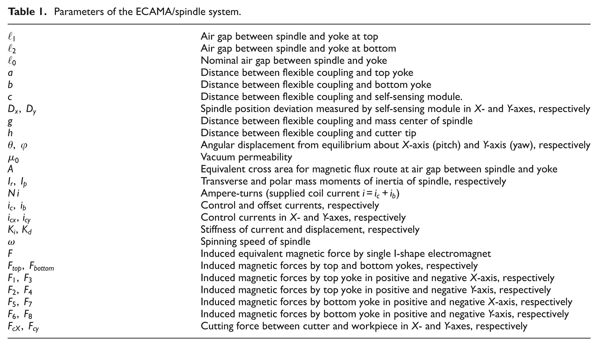
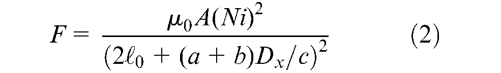
The schematic diagram of the ECAMA/spindle system is shown in Figure 3 and the physical meanings of the corresponding parameters are listed in Table 1. Theoretically, the induced equivalent magnetic force by a single I-shape electromagnet in Figure 3(a) can be expressed as 33
Parameters of the ECAMA/spindle system.
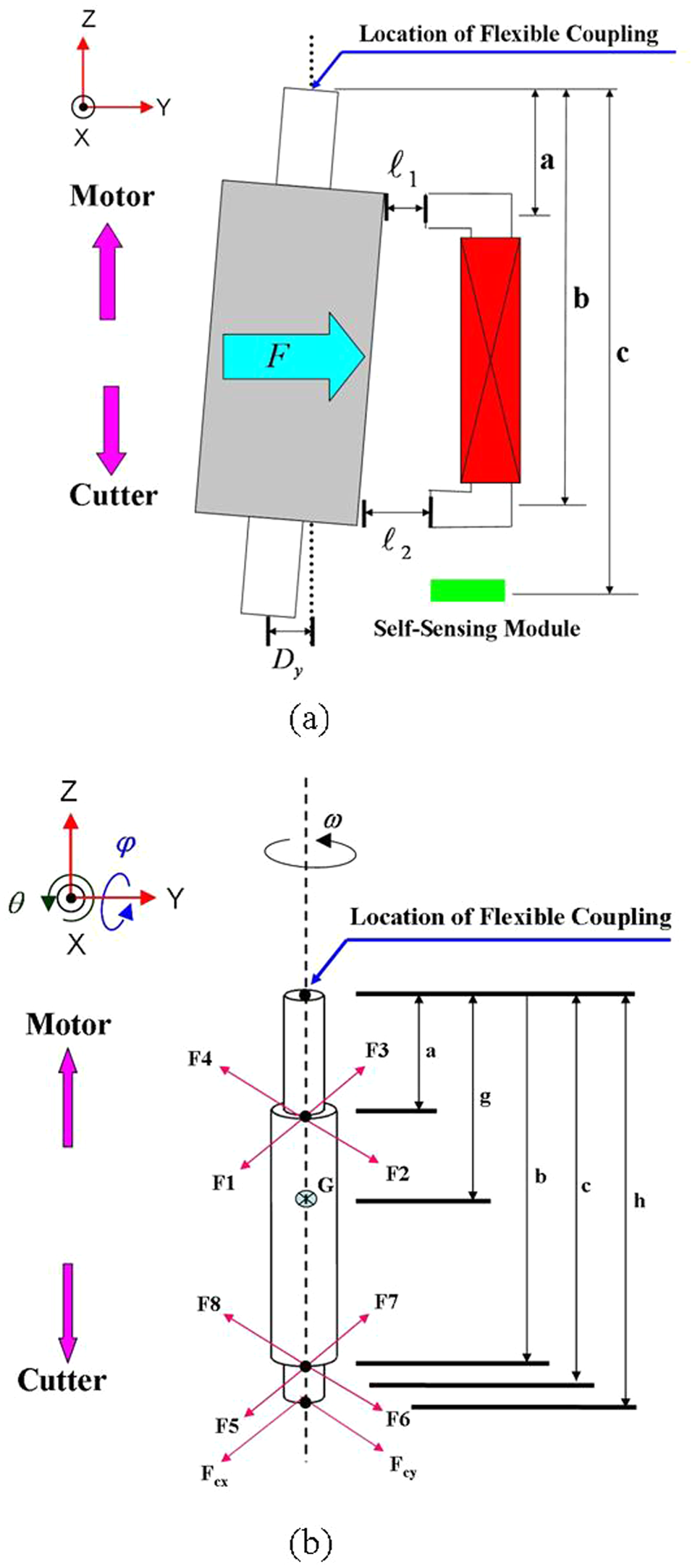
Schematic diagram of the spindle for the ECAMA: (a) position deviation of the spindle and electromagnet at the ECAMA; (b) dimension definition for the spindle.
where

where


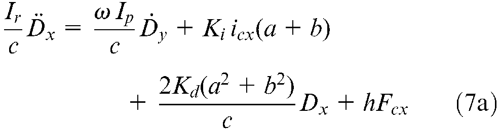
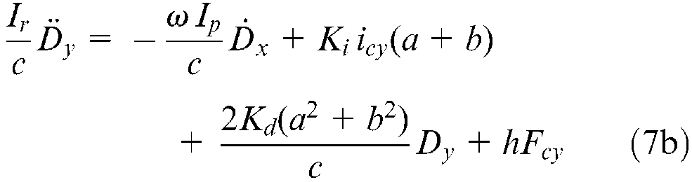
Assume the spindle in Figure 3(b) is a rigid body. The equations of motion of the spindle can be described as


For simplicity of notations,


On the basis of equation (3), equation (5) can be further rewritten in terms of applied control currents as
Now define a state vector,

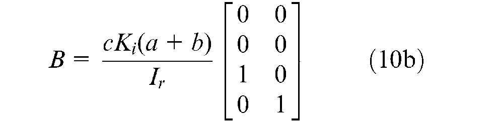
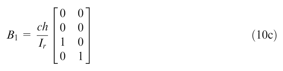
The interested equations of motion in state-space form and the measurement model can be easily obtained


where
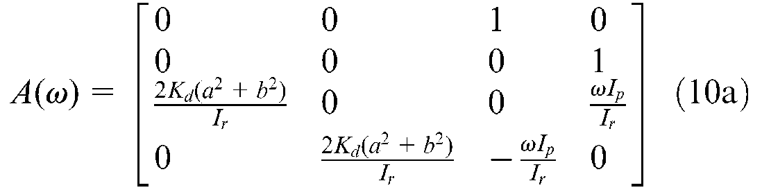
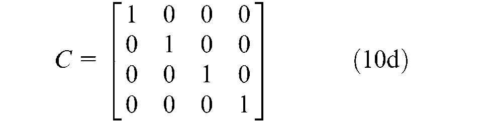
It is particularly noticed that the gyroscopic effect has been included in the system matrix
Control strategy for the anti-windup of the ECAMA
The block diagram of the proposed control strategy for spindle position regulation is shown in Figure 4, where the state feedback gain,
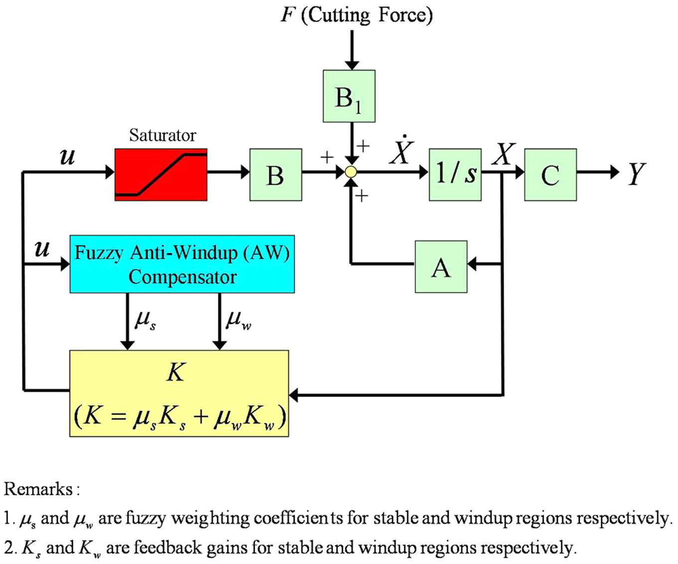
Block diagram of the spindle position regulation system.
Determine the upper and lower limitations of ECAMA, i.e. coil current supplied by the power amplifier. The limitations of the ECAMA will be employed by the fuzzy AW compensator and applied on the normalization of the unconstrained control input for the ECAMA. It is noticed that the only difference between maximum and minimum supplied coil currents provided by the same power amplifier is the current direction. That is, the amplitudes of upper and lower limitations for the coil current are identical, i.e.
Define three levels for the control input to the ECAMA: stable region, buffer region and windup region, as shown in Figure 5. The stable region corresponds to the control input between 2/3 of the upper and 2/3 of the lower limitations. The buffer region is located between the stable and windup regions. It is noticed that the stable and buffer regions are both within the limitations for the ECAMA.
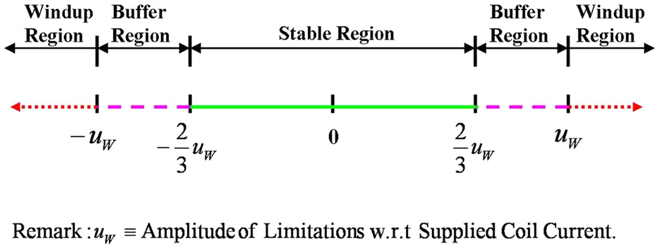
Classifications of control input.
The classification of control input mentioned will be utilized in the procedure of determining the fuzzy weighting coefficients. To sum up, once the required control input is beyond the stable region, the fuzzy AW compensation action is activated.
In terms of the fuzzy logic algorithm, two feedback gains are developed in advance, i.e.
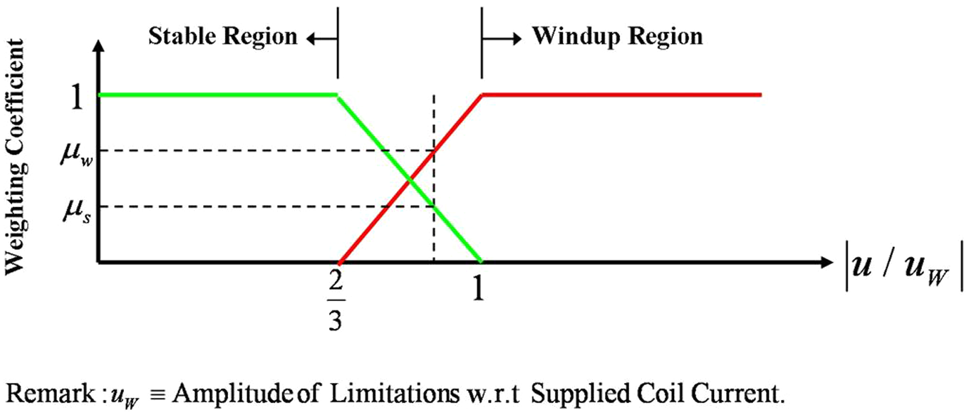
Membership function for the fuzzy AW compensator.

where
Since the ECAMA is composed of four electromagnetic actuators, the discrepancies among the four actuators are also considered in the windup compensation algorithm shown in Figure 7. The four control inputs along the X- and Y-axes are normalized, with respect to the amplitude of limitation, i.e.
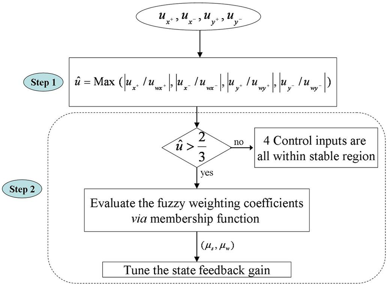
Fuzzy compensation algorithm for actuator windup.
The second step of the fuzzy AW compensation is to evaluate the fuzzy weighting coefficients and tune the feedback gain if the required control input,
Experimental setup and results
In order to verify the function and efficacy of the proposed fuzzy AW compensator, realistic milling experiments for the ECAMA are therefore undertaken. The test rig, including the milling machine, Model CNC-K3 (How-Mau CNC Machinery Co., Ltd), 37 is depicted in Figure 8. Commercial software MATLAB/Simulink and signal processing interface, Module DS1104 (dSPACE), have also been employed in the intensive experiments.
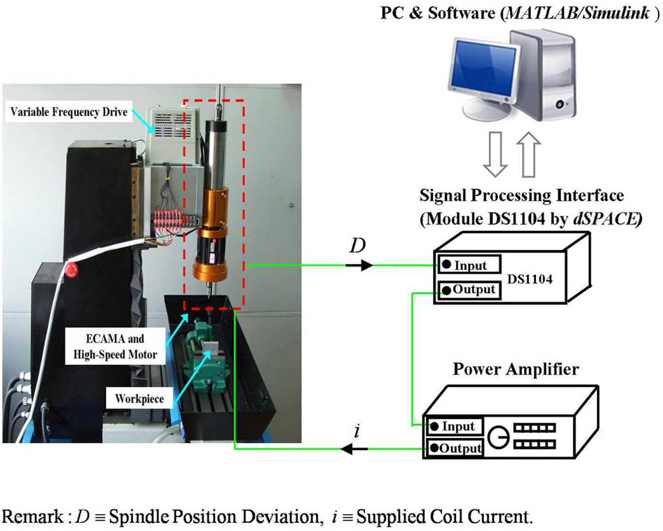
Test rig for the milling operation.
Design of state feedback
The open-loop poles of the ECAMA/spindle dynamic system can be obtained by substituting the physical values into equation (10) as
Open-loop poles of ECAMA/spindle dynamic system:
For the purpose of finding the state feedback gains for the stable and windup regions, two sets of desired closed-loop poles are given, respectively, as
Desired closed-loop poles for stable region:
Desired closed-loop poles for windup region:
The closed-loop poles for the stable region are determined according to the following performance requirements.
Maximum overshoot: 5%.
Damping ratio:
Settling time:
On the other hand, to ensure the efficacy of spindle position regulation by the AW compensator, the closed-loop poles for the windup region are synthesized to provide the same damping ratio as the poles for the stable region, but 25% of the settling time with respect to that of the stable region, i.e.
As a result, the state feedback gains for the fuzzy AW compensator can be given as
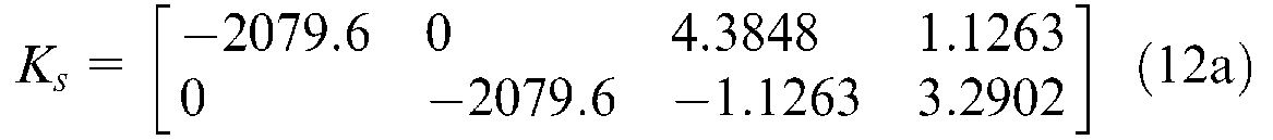
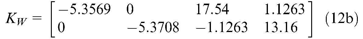
where
Experimental results
For the experiments of spindle position regulation, a cutter of high-speed steel (HSS), with diameter 6 mm and four cutting blades, is equipped. The workpiece used in the tests is made of aluminum. The cutting path is schemed as Figure 9. A protuberance is designed and located at the cutting path to induce a transient rise of cutting force in both the X- and Y-axes. The dimensions of the workpiece and the operation parameters for milling tests are defined as
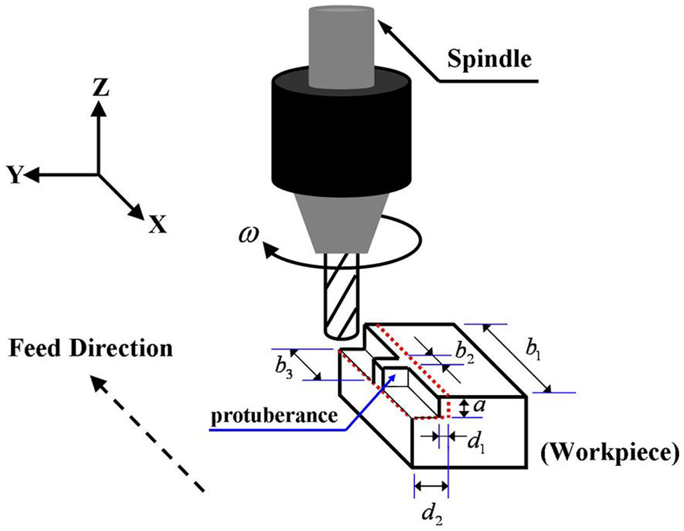
Cutting path.
Spindle speed (
Feedrate (
Axial cut depth (
Radial cut depth: 1mm (
Width of workpiece (
Width of salient (
Distance between start point and protuberance (
The experimental results are shown in Figures 10–13. The required coil currents for the ECAMA in the X- and Y-axes, respectively, under various control laws are shown in Figures 10 and 11. The associated spindle position deviation in the X- and Y-axes, respectively, are shown in Figures 12 and 13.
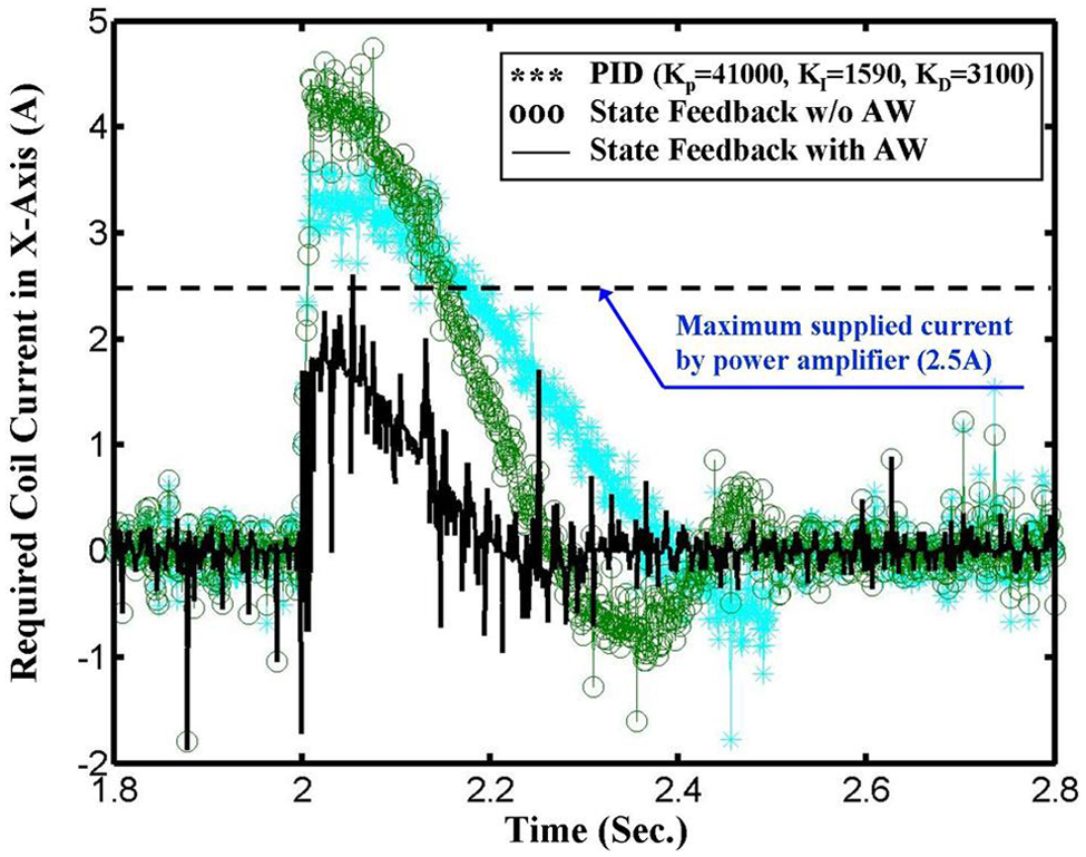
Comparison of required coil current for the ECAMA in the X-axis under various control laws.
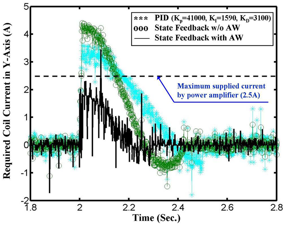
Comparison of required coil current for the ECAMA in the Y-axis under various control laws.

Spindle position deviation in the X-axis under various control laws.
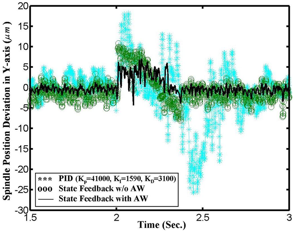
Spindle position deviation in the Y-axis under various control laws.
The dotted lines in Figures 10 and 11 are the upper limit of current output provided by the power amplifier. That is, the windup phenomenon takes place once the required coil current exceeds over the dotted line. It is obvious that the windup phenomenon occurs and lasts a while (about
Comparison among various control laws for required coil current and resulted spindle position deviation.
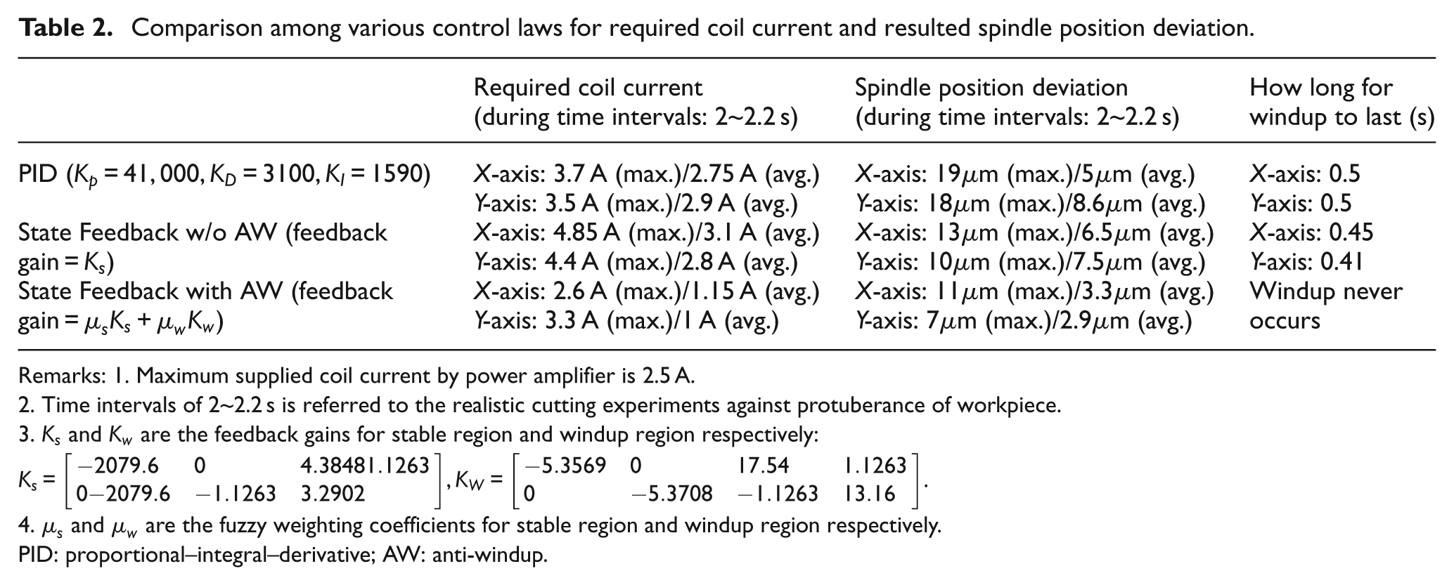
Remarks: 1. Maximum supplied coil current by power amplifier is 2.5 A.
Time intervals of 2~2.2 s is referred to the realistic cutting experiments against protuberance of workpiece.
PID: proportional–integral–derivative; AW: anti-windup
Conclusions
The fuzzy AW compensator is proposed to incorporate with state feedback loop and applied to the ECAMA designed for spindle position regulation of the high-speed milling process. From the experimental results, owing to the proposed fuzzy compensation strategy, the required coil current by state feedback with AW compensation is significantly reduced (about 50%), compared with PID control or state feedback law w/o AW compensation. The maximum spindle position deviation is also successfully improved prior to potential windup occurrence. Actually, the proposed AW strategy can be applied to most active magnetic actuators, such as motors, solenoids and electricity generators. The forthcoming researches by the authors are to extend the fuzzy AW strategy and the ECAMA to manufacture electric/optical components, propellers and variable pitch screws. Since the required precision and reliability for these components are much stricter than those by conventional machining, the design of the AW strategy can be applied and becomes more suitable, especially for high-precision milling applications.
Footnotes
Funding
This research received no specific grant from any funding agency in the public, commercial, or not-for-profit sectors.