
Abstract
Inheritance and innovation play important roles in the conceptual design phase. Inheritance can achieve rapid design by reusing existing design knowledge, while innovation can realize innovative design by developing creative ideas and concepts. Thus, an ideal conceptual design model should administer to the implementation of inheritance and innovation. Considering rational design domains and mapping relations is beneficial to knowledge representation and inheritance. According with the thinking process of humans it is propitious to human intervention and innovation. To meet these requirements, this article proposes a hierarchical functional solving framework with hybrid mappings. In this framework, there are four design domains including function, working principle, behaviour and structure. The reasoning process of product function design consists of four mapping patterns, which are solving mapping pattern, reformulation mapping pattern, decomposition mapping pattern and derivative mapping pattern, totalling 15 basic mapping relations. The evolutionary logic of these mapping relations is developed in this article. In addition, the flow of the solving process from each design domain is established. The procedure in applying the proposed framework to the conceptual design is presented subsequently. Moreover, several embodiment strategies ensuring the effectiveness of identified design solutions are also proposed, including performance match analysis, behavioural compatibility analysis and structural compatibility analysis. Finally, a design case of the telescopic shuttle mechanism of an automatic storage/retrieval machine is studied to illustrate and demonstrate the feasibility of the proposed framework.
Keywords
Introduction
Starting with the abstract, uncertain and qualitative demands, the conceptual design obtains the specific, determined and quantitative solutions by mapping from functions to structures. As stated by many researchers, the conceptual design represents more than 70% of the costs and performance of the product being designed. 1 Owing to the importance and better understanding of the conceptual design, researchers have established various models to describe the design process of the conceptual design. In accordance with the evolutionary course, the proposed functional solving models of the conceptual design can be divided into three stages: direct functional solving, behaviour-assisted functional solving and functional solving with environmental constraints. 2
At the first stage, the function is reasoned to structure directly with the so-called direct functional solving models. The most prominent two are the systematic design model3,4 and the axiomatic design model. 5 At the second stage, the behaviour-assisted functional solving model is developed based on the direct functional solving model. Behaviour is considered as the intermediate element and the information bridge in order to settle the mapping obstruction between function and structure. Two typical behaviour-assisted functional solving models are the function–behaviour–state model 6 and function–behaviour–structure model. 7 At the third stage, design models in consideration of environmental constraints are proposed. These models incorporate various design factors into the design reasoning process in order to ensure the effectiveness and accuracy of the design results. For example, the function–environment–structure path model, 8 the function–environment–behaviour–structure model 9 and the behaviour-driven function–environment–structure model 10 have been presented in previous studies.
According to the specific requirements of certain fields or objects, adaptations to the above models have been made by researchers. Several improved and expanded models have been developed, such as the Freeman–Newell model, 11 function/means tree model, 12 function–effect–working principle–abstract structure model, 13 functional solving model with multiple elements and evolutions, 2 function to structure/material mapping model, 14 require–function–behaviour–structure model, 15 function–behaviour–physical phenomenon-state model 16 and multi-relational synthesis model. 17
The aforementioned functional solving models, which take into account diverse elements such as function, environment, effect, principle, behaviour, mechanism and structure, are very useful for design problem solving and design knowledge management. These models can be generally expressed as function–X–structure, where the X is determined by the concrete circumstances, such as the product type and the design focus.
Inheritance and innovation are fundamental and necessary to assist in the development of the conceptual design. Inheritance can achieve rapid design by reusing existing knowledge, while innovation can realize innovative design by developing creative ideas and concepts. Thus, an ideal conceptual design model should administer to the implementation of inheritance and innovation so as to provide a more flexible and effective model. This model needs to satisfy the following objectives.
To consider rational design domains and mapping relations for knowledge representation and reuse.
To support several different mapping patterns and mapping relations, and to implement a flexible solving process by diverse mappings.
To be consonant with the thinking process of humans for human intervention at any time.
To support multi-domain and multilevel innovative design.
To allow the designers to describe and solve a design problem from any domain or level.
Therefore, on the basis of the function–behaviour–structure (FBS) model, this article proposes a new hierarchical functional solving framework with hybrid mappings among the function domain, the working principle domain, the behaviour domain and the structure domain. We name this framework as the FPBS. This framework not only incorporates the ‘working principle’ domain to the FBS model, but also adapts the mapping relations, the evolutionary logic and the solving process of the FBS model according to the above objectives. Our proposed framework can balance rapid design with innovative design by integrating inheritance with innovation.
In ‘The FPBS framework’, the concepts of function, working principle, behaviour and structure are presented. The multilevel hybrid mapping relations among these design domains are elaborated and the detailed meanings of these mapping relations are explained too. In ‘Design reasoning scheme and procedure’, the evolutionary logic of the mapping relations is then developed. In addition, the solving process is established for each domain. In ‘Conceptual design based on FPBS framework’, the procedure in applying the FPBS framework to product conceptual design is presented. Several embodiment strategies that ensure the effectiveness of identified solutions are proposed. A design case study and a prototype software are discussed in ‘Case study’ before conclusions are drawn.
The FPBS framework
Problem-solving process of humans
In order to make preparations for establishing rational design domains and mapping relations, two products are taken to analyse the problem-solving process of humans.
A problem-solving process starts from a function and ends with a structure. For instance, the function of a clock is to time, while the structure is the assembly of long and short hands. People can read time from the positions of three hands. The ‘to time’ function is achieved by a regular rotation of the structure, which is considered as a behaviour. We know that there are several different types, such as mechanical clocks, electronic clocks and digital clocks. These clocks have the same functions, structures and behaviours; however, their dissimilar working principles bring about different capabilities of the products and other impacts. The function of a fan is to blow wind. The traditional fan blows wind by rotating the fan blades at a high speed. Therefore, the behaviour of a traditional fan is a high-speed rotation and the structure is an assembly of fan blades and other accessories. An air multiplier fan is a new type of fan whose function is to blow wind as well, but its working principle is absolutely different from the traditional fan. This difference in working principle leads to distinct behaviours and structures.
The two instances show that the working principle plays an important role in the problem-solving process. Thus, by inserting the working principle into the FBS model, an extended design domain is generated, and the new model includes function, working principle, behaviour and structure (FPBS). The functional solving process is commonly accomplished by designers in three steps.
Determining the working principle to realize the required function.
Obtaining the behaviour which is the embodiment of the working principle.
Looking for the structural carrier which can support this behaviour.
Design domains
Function domain
The function is involved with several factors, such as research field and circumstance. There are two main viewpoints on functional cognition in the design field: one concentrates on the teleology and the other concentrates on the operation. In the teleological focus, the function represents the purpose from the viewpoint of a designer, which is an abstraction of the use of a design. In the operational focus, the function is a description of the intended operation of the design, which is an abstraction of the useful behaviour that a design exhibits when it is put under its working conditions. Deng and Zhu called them purpose function and operation function, respectively. 14
In addition, human interpretation plays an important role in functional cognition and functional representation. Unfortunately, lots of the representations of the function are usually not rational, because the designer’s understanding is incomplete or incorrect. A prevalent problem is that the functional representation implies its realization way, which is called ‘way function’. Way function is a composite of ‘what to achieve’ and ‘how to achieve’, for example ‘to weld’ is a composite of ‘to join’ and ‘fusing way’. 18 Way function, which is the most dominant and dangerous type among functional representations, does a lot of harm to product design as follows.
There must be multiple ways of realization of a function. The solution space of product innovation design will be restricted and narrowed if the way of function achievement is specified in advance.
The way function prevents the extraction, share and reuse of functional knowledge across domains, since ‘how to achieve’ bears the domain-specific things.
The way function obstructs the interdisciplinary and multidisciplinary design.
From the teleological viewpoint, the function, which is the purpose of the design being designed, emphasizes ‘what to do’, and people are not interested in how the function is realized. One of the most significant properties of function is implementation-independence. 18 The way function must be separated into two parts: function and way. The former is the function element in this study.
Working principle domain
The way extracted from a way function, and determined by a working principle, specifies the means to achieve the function. Principle is the essence of way. 19 Working principle represents the inherent reason of function realization and provides the scientific evidence to suggest that function is achieved by structure.
There could be multiple working principles to realize a given function. Different working principles lead to dissimilar behaviours and structures. Therefore, when the way function is divided into the function and the way, the conventional FBS model that maps function to behaviour directly does not accord with the thinking process of humans. If the function was a way function, direct function-to-behaviour mapping could be implemented smoothly. However, as is stated above, way function is an ill representation. In this research, the working principle domain should be constructed between the function domain and the behaviour domain.
Behaviour domain
Behaviour is related to the physical state of the behaviour actor. Generally, behaviour is regarded as a physical state transition of the behaviour actor; or regarded as the physical interactions between the behaviour actor and its environment. 14 From this viewpoint, the behaviour is dynamic. Generalized behaviour can be regarded as a physical state transition or maintenance of the behaviour actor, which is considered to represent the external characteristics of components when the required function is achieved. From this viewpoint, behaviour can be either dynamic or static.
We take the standpoint of the latter in our research. Behaviour is regarded as a movement or an action of a component that can realize a specific function. The behaviour is the embodiment of the working principle and is implemented by the structure. The overall function of a product may be provided by a behavioural process consisting of a number of individual behaviours rather than by a single behaviour of a structure. The behaviour describes the intermediate states of a physical component and precise values for the flows and states. 17 Thus, the behaviour can be represented by some parameters. Especially, the behaviour of mechanical products can be described with kinematic parameters, such as displacement, velocity, acceleration, angular displacement, angular velocity, angular acceleration and force. 20
Structure domain
As the carrier of the function, the structure is the result of the product design activity. The structure achieves a specific function through a certain movement. In this work, the structure can be a module, an assembly, a part or a feature.
Basic mapping relations
The conventional FBS model solves a given function by means of one-way, one-pass and layered mappings, and lacks the integration of designers’ experiential knowledge and diverse solving routes. This is not accordant with the actual design process. Quoting Dorst and Vermaas, 21 “if the model is meant to describe real world designing, then surely actions like the ‘jump’ from function to structure have to be incorporated in the model.”
In order to make up for the deficiencies of the conventional FBS model, the proposed framework in this study makes use of hybrid mappings to implement the conversion, decomposition and synthesis of design elements. Figure 1 shows the hybrid mapping relations of the FPBS framework.
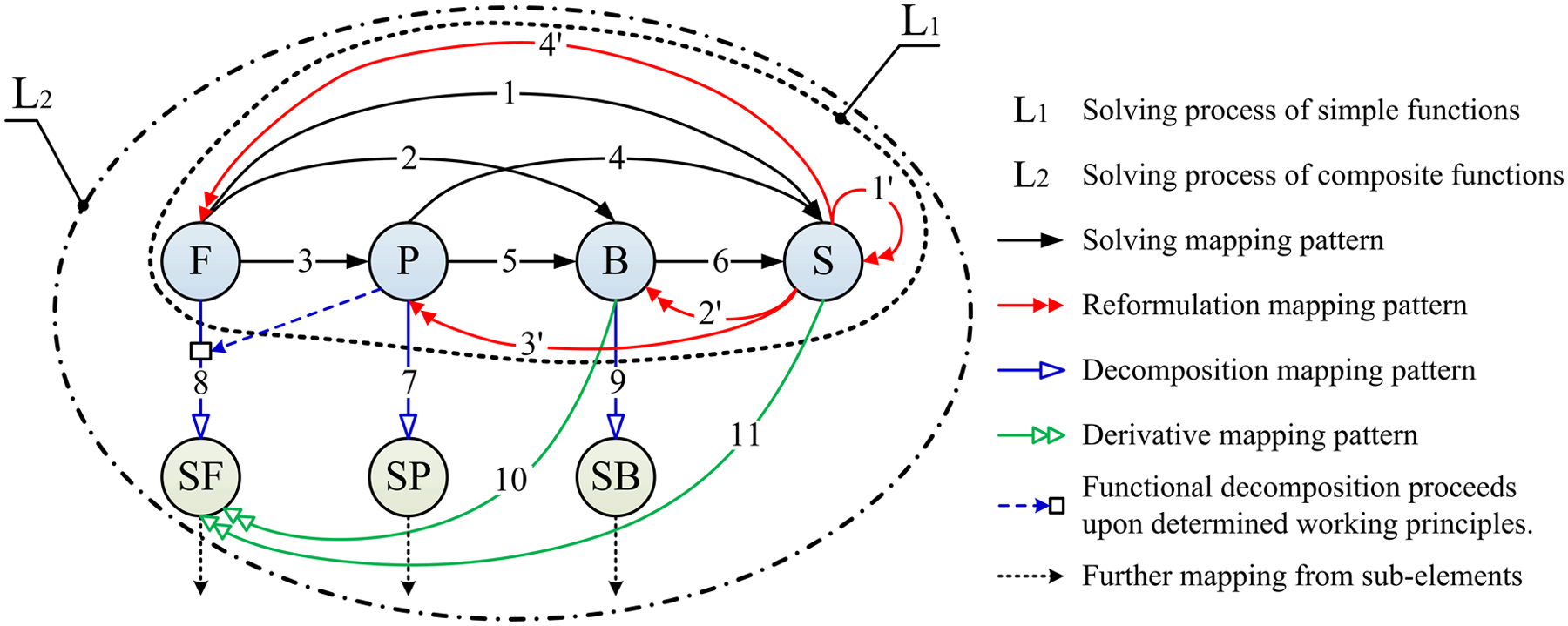
Hybrid mapping relations of the FPBS framework.
The function domain and the working principle domain link the human intentions to the behaviour domain and the structure domain. Figure 1 contains two functional solving paradigms denoted by L1 and L2, respectively. L1 is the subset of L2. The design elements of L1 are the function, the working principle, the behaviour and the structure. L2 has more elements than L1: sub-function (SF), sub-working principle (SP) and sub-behaviour (SB). L1 is applicable to simple functions that do not need to (or can not) be decomposed, and L2 is suitable for complex functions that are comprised of multiple simple functions with a certain logic.
There are four mapping patterns in Figure 1: solving mapping pattern (SMP), reformulation mapping pattern (RMP), decomposition mapping pattern (DecMP) and derivative mapping pattern (DerMP).
SMP achieves one-pass and by-pass conversion of the design elements. SMP includes F→S, F→B, F→P, P→S, P→B and B→S.
RMP can be applied to the situation where the actual behaviour is not consistent with the expected behaviour and could not be adapted to satisfy the design requirements. The reverse mappings in L1 can be delivered by RMP. RMP includes S→S′, S→B′, S→P′ and S→F′.
DecMP can be adopted to solve the abstract and complex design elements by decomposing them into some simpler sub-elements. DecMP includes P→SP, F
DerMP should be considered when the obtained results have to rely on accessional elements to realize the required function. DerMP includes B→SF and S→SF.
The 15 basic mapping relations among function, working principle, behaviour and structure, as well as their physical meanings, are listed in Table 1. As a matter of fact, not all the basic mapping relations, but some of them appear simultaneously in a specific design process.
Physical meaning of the basic mapping relations.
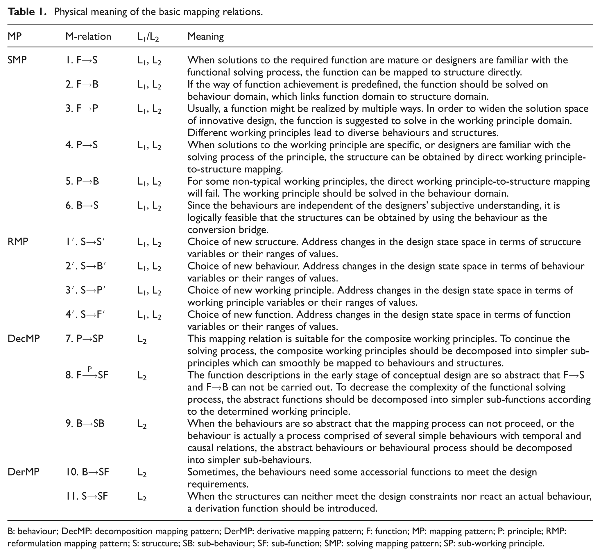
B: behaviour; DecMP: decomposition mapping pattern; DerMP: derivative mapping pattern; F: function; MP: mapping pattern; P: principle; RMP: reformulation mapping pattern; S: structure; SB: sub-behaviour; SF: sub-function; SMP: solving mapping pattern; SP: sub-working principle.
Characteristics and improvements
The four mapping patterns and the 15 hybrid mapping relations can better help to incorporate such actions like the ‘jump’ from function to structure in the FPBS framework. These actions are the direct embodiment of the experience of the designers. Therefore, the framework can well support the reuse of the design knowledge and the design experience.
The working principle, which represents the essential reason of a function achieved, is the core of a design. Principle innovation is the soul of product innovation. Thus, extracting working principles from the way function and treating it as a single design element to administer to innovative design.
As described above, by integrating inheritance with innovation, the FPBS framework can strike a balance between rapid design and innovative design. Comparing with other previous functional solving models, especially the FBS model, the FPBS framework shows some positive improvements.
Certain design elements that convey product information ─ F, P, B, S ─ are clearly defined. Working principle is separated from way function for the first time.
Various mapping relations among different design elements accord with real-world designing and could reproduce the functional solving process by humans.
By means of the design elements and the mapping relations, the design solution space of a given function will be expanded, in which rapid design solutions and innovative design solutions may exist.
The FPBS framework can provide the right means to system developers for building computer tools to aid designers.
The proposed framework will retrogress to the FBS model when the given function is a way function. In other words, a purpose function, which is realization-independent, is difficult, or hardly even solved, in the absence of a working principle.
Design reasoning scheme and procedure
Mapping evolutionary logic
For a concrete design problem, the designers adopt diverse solving routes to solve it from its functionalities to the physical abstraction of the solution. The solving route is organized by the mapping relations according to the evolutionary logic.
The evolutionary logic of the mapping relations, starting from the function element, is shown in Figure 2. We define Ф as the satisfactory structure distinguishing the structure to be mended. That is to say, S→Ф represents the termination of a design process. 2
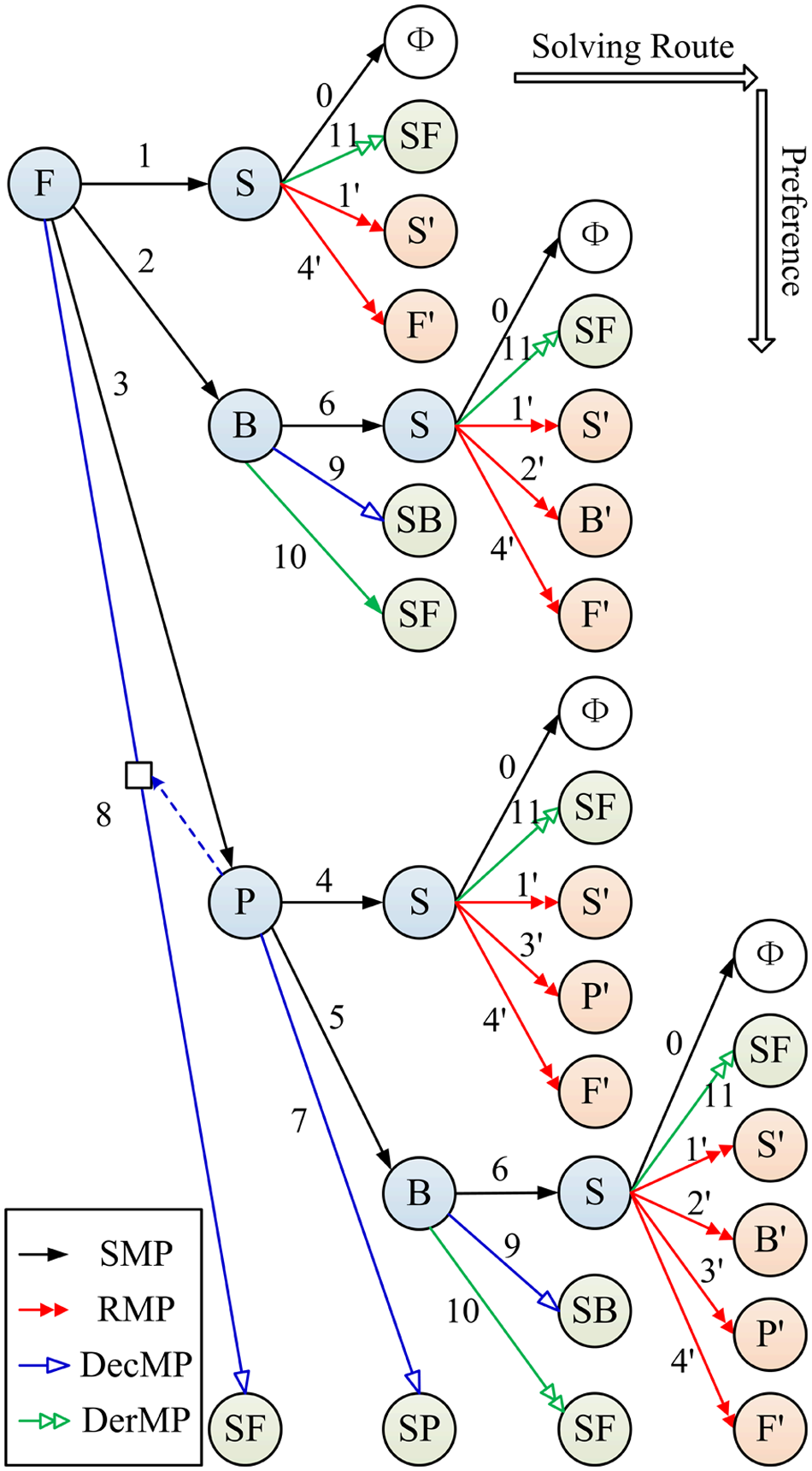
Mapping evolutionary logic from function.
As shown in Figure 2, the horizontal direction represents the solving routes and the vertical direction represents their preference. The solving route is marked with a labelled arrow line, for example ‘3-5-6-11’ corresponds to ‘F→P→B→S→SF’.
The preference of the solving route lies on two aspects:
for inheritance, the time of searching for design knowledge;
for innovation, the difficulty of innovative design.
A shorter solving route spends less time to obtain required knowledge from the libraries than a longer one. Innovative design realized on the structure domain is easier than that on the behaviour domain, that is to say, the difficulty of innovation is increasing in the following sequence: structure, behaviour, working principle and function. Therefore, the shorter a solving route is, the higher its preference is. The preferential solving route that depends on the design knowledge libraries and the designers’ experience much more should be given implementation priority. The priorities of the mapping relations are as follows.
(F→S) > (F→B) > (F→P) > (F
(B→S) > (B→SB) > (B→SF)
(P→S) > (P→B) > (P→SP)
(S→SF) > (S→S′) > (S→B′) > (S→P′) > (S→F′)
Here, the sign “>” means that the left-hand side mapping relation is more preferential than the right-hand side one.
Solving process from design elements
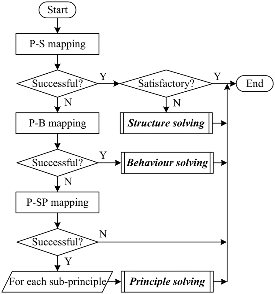
Solving process from function
According to the priority of the mapping relations from the function element, F→S should be carried out in the first place. When this operation is successful but the obtained structure can not satisfy the design constraints, the solving process will jump to the ‘structure solving’ process (‘Solving process from structure’). Otherwise, F→B should be implemented secondarily. If it is successful, the solving process will jump to the ‘behaviour solving’ process (‘Solving process from behaviour’). Otherwise, F→P could proceed to determine a working principle of functional achievement. If it is successful, the solving process will jump to the ‘principle solving’ process (‘Solving process from working principle’). Otherwise, F
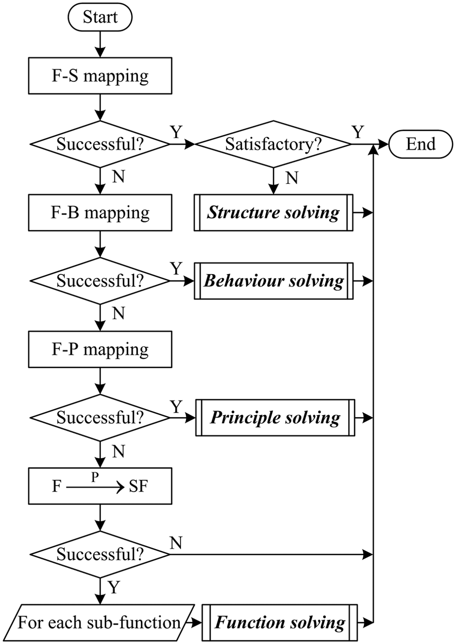
Flowchart of a function solving process.
Solving process from working principle
P→S should be performed first according to the priority of the mapping relations from the working principle element. When this operation is successful but the obtained structure can not meet the design requirements, the solving process will jump to the ‘structure solving’ process (‘Solving process from structure’). Otherwise, P→B should be tried secondarily. If it is successful, the solving process will jump to the ‘behaviour solving’ process (‘Solving process from behaviour’). Otherwise, it means that the current working principle is so abstract that P→SP must proceed to decompose the abstract principle to simpler sub-principles. When it is successful, the foregoing process needs to be executed over again for each sub-principle. Figure 4 shows the solving process from the working principle domain.
Flowchart of a working principle solving process.
In case all mapping operations from a working principle element fail, either the prior design element-function is proved to be too abstract to settle at the current level of granularity or the selected working principle is not the right choice for the required function. Thus, the solving process must terminate immediately and return to the prior design element.
Solving process from behaviour
In the light of the priority of the mapping relations from the behaviour element, B→S should be operated in the first place. When this mapping is successful but the obtained structure can not be able to fulfill the design requirements, the solving process will jump to the ‘structure solving’ process (‘Solving process from structure’). Otherwise, the present behaviour is likely to be very abstract or the behaviour is actually a process comprised of several simple behaviours with temporal and causal relations, B→SB should be adopted to decompose the abstract behaviour or behavioural process to simpler sub-behaviours. For each sub-behaviour, the foregoing process needs to be performed over again. If B→SB fails, sub-functions under the present behaviour should be obtained by B→SF. For each sub-function, the ‘function solving’ process (‘Solving process from function’) could be implemented. Figure 5 shows the solving process from the behaviour domain.
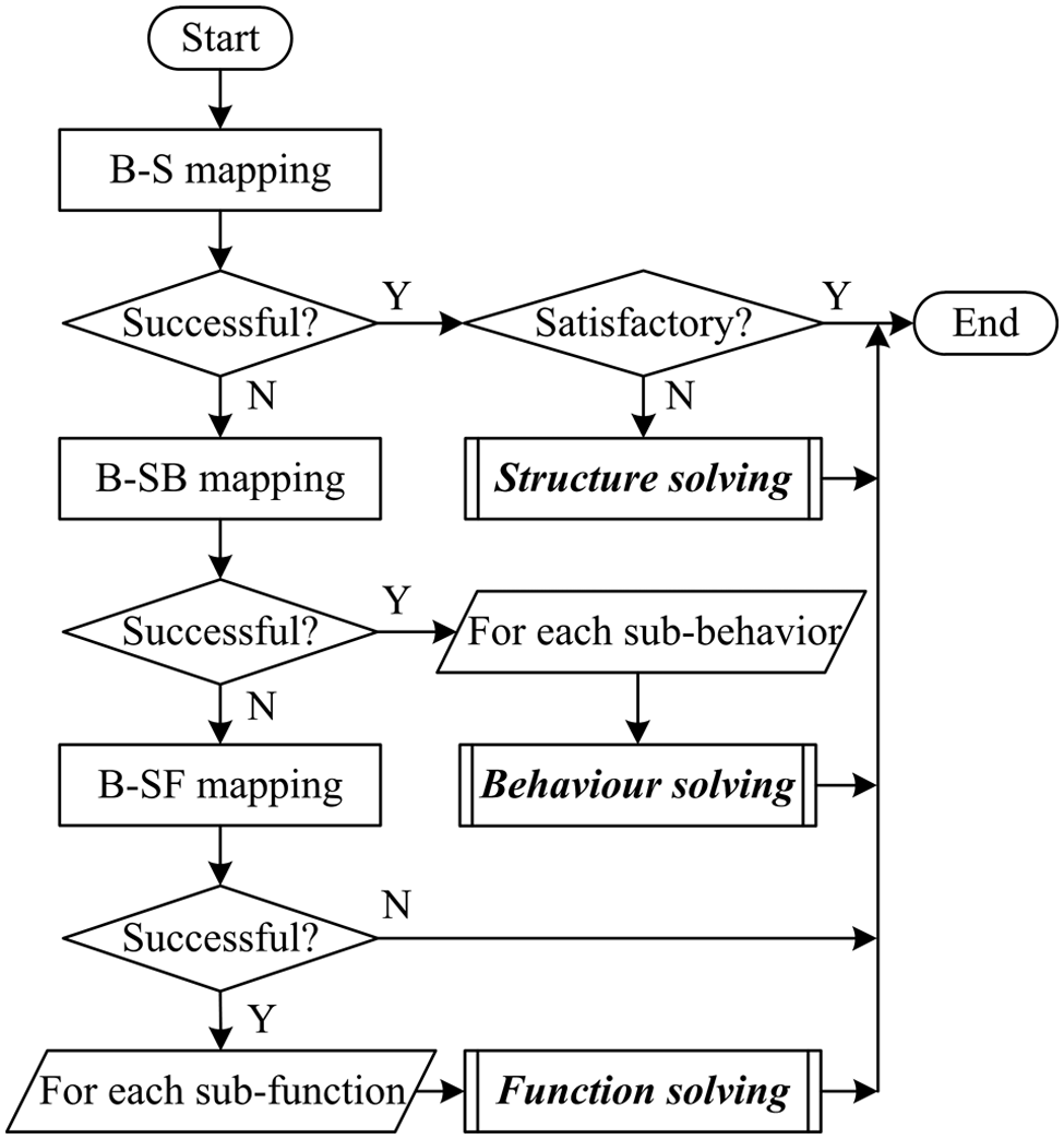
Flowchart of a behaviour solving process.
Solving process from structure
Structure is the final destination of the conceptual design. When an obtained structure during the solving process from a function/working principle/behaviour element could not completely fulfil the design constraints, the structure should continue to be solved by means of S→SF and RMP.
Since the structure of a conceptual design solution is no more than a fundamental skeleton that provides the primary function and behaviour, some accessorial functions are possibly needed to support functional achievement. S→SF is suitable for this situation.
The situation that the structure could not solve is further produced owing to a wrong previous mapping process. Thus RMP should be considered to go back to a proper design element that needs to be reformulated according to the current structure.
Figure 6 describes the solving process from the structure domain.
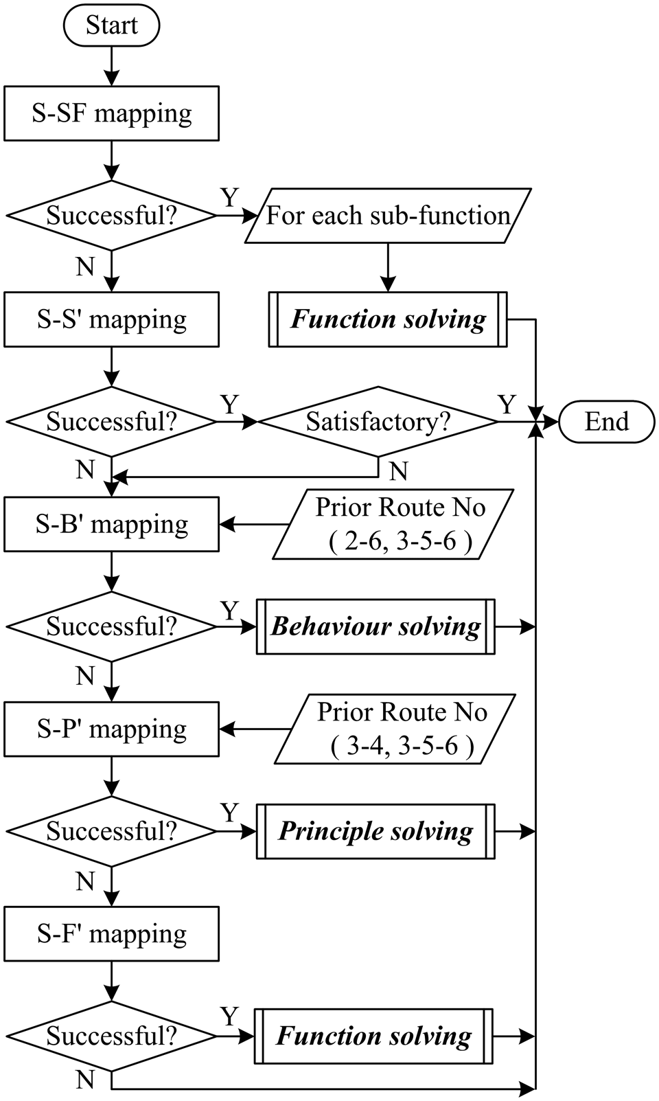
Flowchart of a structure solving process.
According to the priority of mapping relations from the structure element, S→SF should be carried out first to acquire the necessary accessorial functions. If this mapping is successful, the ‘function solving’ process (‘Solving process from function’) could be implemented for each accessorial function at sub-layer. If S→SF fails, S→S′ should be used to reformulate the design state space and generate a new structure. While the new structure can not suffice the designer, S→B′, S→P′ and S→F′ are taken into account.
When the prior solving route of the current structure is either ‘2–6’ (F→B→S) or ‘3–5–6’ (F→P→B→S), S→B′ is tried to complete by preference, and the solving process will jump to the ‘behaviour solving’ process (‘Solving process from behaviour’) once the mapping is successful. Otherwise, S→F′ needs to be performed and the solving process will jump to the ‘function solving’ process (‘Solving process from function’).
If the prior solving route of the current structure is either ‘3–4’ (F→P→S) or ‘3–5–6’ (F→P→B→S), S→P′ should be implemented in order of preference, and the solving process will jump to the ‘principle solving’ progress (‘Solving process from working principle’) once the mapping succeeds. Otherwise, S→F′ needs to be adopted and the solving process will jump to the ‘function solving’ progress (‘Solving process from function’).
Conceptual design based on FPBS framework
Procedure in applying the FPBS framework
The FPBS framework may be applied to implement a conceptual design synthesis. The procedure in applying the FPBS framework is shown in Figure 7. First of all, the overall function should be obtained from the design requirements. The representation of the overall function ought to be realization-independent so as to ensure the design solution space. Then, the design process proceeds from the overall function by means of function solving, principle solving, behaviour solving and structure solving. The way of logical reasoning of computers by automatically searching design knowledge libraries is combined with the way of innovative solving of designers by manually operating in the conceptual design process. When the innovative mapping knowledge generated by the experienced experts is proved to be valid, it should be stored in the design knowledge libraries for reuse.
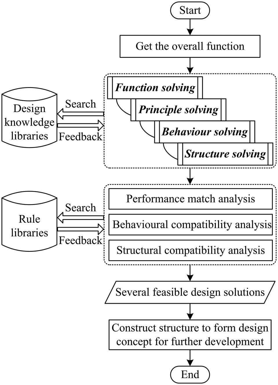
Flowchart of a conceptual design process based on the FPBS framework.
The mapping relations among the different design domains are many–many relationships that can be expressed with ‘and/or’ relations. Therefore, the solution space will constantly expand along with the progress of design solving. To avoid this problem, some supportive strategies should be considered during the functional reasoning process in order to discover the infeasible solving routes and to eliminate the invalid design solutions as soon as possible. These strategies include performance match analysis, behavioural compatibility analysis and structural compatibility analysis, which rely on rule libraries and the experience of designers.
Eventually, all the identified structures can be constructed to form some complete design solutions.
Rules in verifying design solutions
Performance match
Since the product design activity is driven by functions, the developed design solutions can naturally meet the customers’ functional demands. This is a so-called functional match. In addition, the design concepts must satisfy some performance constraints, namely performance match. The performance constraints are represented as qualitative or quantitative descriptions of the requirements of the level or quantity relating to some functions. 14 For instance, assume that a required function is ‘to move the object from point A to point B’, which has a performance constraint: ‘the time for movement should be less than ten seconds’. In this situation, when a design solution needs to spend more than 10 s to realize this function, it does not meet the performance constraint and should be abandoned because of a performance mismatch.
Behavioural compatibility
Behavioural compatibility is necessary and fundamental to achieve a desired function. All related behaviours generated during the design process should be checked for compatibility. When mutually exclusive behaviours are discovered, the design concept should be eliminated. Behaviour compatibility mainly embodies the following aspects. 20
All behaviours must be able to coexist in the developed design solution.
A product is constructed by connecting several structural components. If the components are either fusional or fastened, their behaviours will be consistent. If the components engage with each other, their behaviours will not be the same but correlative. If the components are connected with elements that can provide a relative movement, e.g. bearing, their behaviours will be different and correlative.
The behaviours of different structural components could perform without temporal interference and spatial interference. When all behaviours are proceeding, the structure keeps stable and achieves the function reliably.
Structural compatibility
Structural compatibility is similar to behavioural compatibility, including interface correspondence and arrangement feasibility. Interface correspondence demands that the interface type and specification of two components that need to be assembled together to form a higher-level assembly are absolutely matching. For example, assume that two gears are used to construct a gear bank, their interface type ‘tooth shape’ and interface specification ‘modulus’ must be equivalent.
Arrangement feasibility refers to non-interference of structural components during the structure aggregation process. This puts forward strict demands to the spatial location and the component size.
Other rules
In order to determine the effectiveness of the obtained design concepts, performance match analysis, behavioural compatibility analysis and structural compatibility analysis are basic and obligatory. Besides these, other rules can be applied to check the effectiveness of the design solutions according to different design requirements. Some typical analysis ways are as follows.
Design for manufacturing: manufacturability analysis.
Design for disassembly: removability analysis.
Adaptable design: adaptability analysis. 22
Design for cost: cost analysis.
Case study
In this section, a functional solving instance regarding the telescopic shuttle mechanism of an automatic storage/retrieval machine will be studied to illustrate the mapping relations, evolutionary logic and supportive strategies of the FPBS framework.
Design process
A storage/retrieval machine is the main operation device of the automated warehouse to store and retrieve cargo automatically. The telescopic shuttle mechanism, which is the actuator of the automatic storage/retrieval machine, locates on the board and lifts/lowers to the target position along the pillar. Cargo is exchanged between the storage/retrieval machine and the automated warehouse by pushing and pulling the bracket tray of the telescopic shuttle mechanism. Therefore, the main function of this component is to push/pull cargo regularly. The design parameters are listed below.
The extending/retracting speed of shuttle: 20-24 m/min.
The maximum extension of shuttle: 2.5 m.
The addressing precision: ≤ 2 mm.
The load lifting capacity: 300 kg.
There are various known solutions to this design problem. Our focus is not on the novel solutions, but rather on how to develop design solutions by using the proposed functional solving framework, as shown in Figure 8. The typical triple-differential principle is adopted to meet the extending/retracting speed of the shuttle and the three-ply structure is generated accordingly, including under layer, middle layer and upper layer. All the symbols in Figure 8 are explained in Table 2.
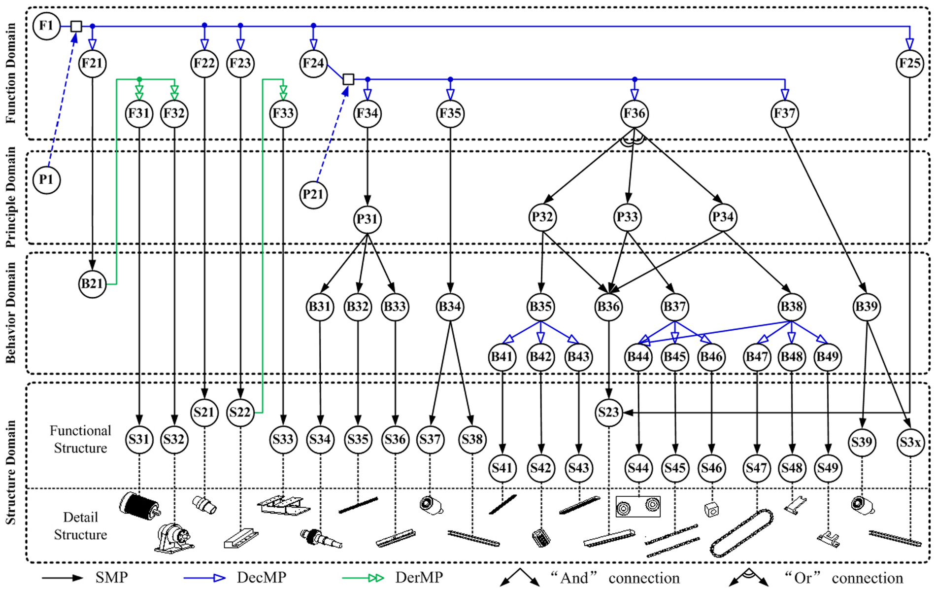
The design process of a telescopic shuttle mechanism based on the FPBS framework (partly).
Descriptions of the symbols in Figure 8.
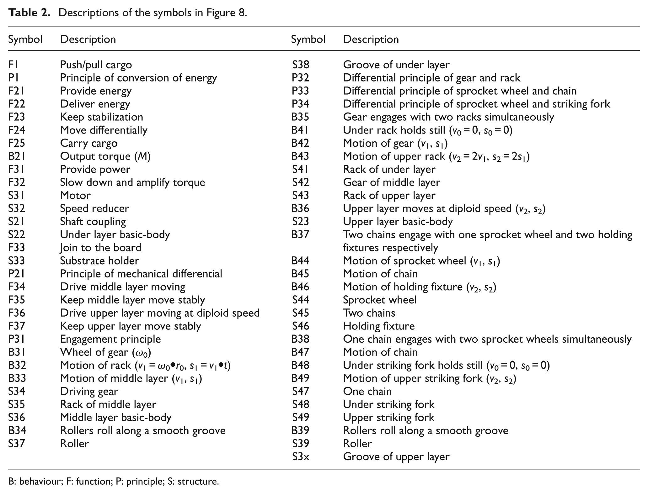
B: behaviour; F: function; P: principle; S: structure.
The design process starts with the overall function of the telescopic shuttle mechanism: ‘push/pull cargo’ (F1). Since the function is so abstract that F→S, F→B and F→P fail to be executed. F
The mapping F→B is successfully implemented and F21 can be realized by outputting torque (B21). B21 is too abstract to obtain a structure directly, therefore, the mapping B→SF is executed and two sub-functions can be derived from B21: ‘provide power’ (F31) and ‘slow down and amplify torque’ (F32). F31 can be directly mapped to a motor (S31) by the mapping F→S while F32 can be mapped to a speed reducer (S32). S31 and S32 are satisfactory and then F21 is solved successfully.
F22, F23 and F25 are all simple and the mapping F→S will be applied to them. F22 is mapped to a shaft coupling (S21), while F23 is mapped to the under layer basic-body (S22) and F25 mapped to the upper layer basic-body (S23). However, S22 can neither meet the design constraints nor react to an actual behaviour. A derivation function ‘join to the board’ (F33) is then introduced, which can be directly mapped to a structure –‘substrate holder’ (S33). Thus, the problem of F22, F23 and F25 are finally settled.
F24 are so abstract that F→S, F→B and F→P can not be carried out. The mapping F
Function elements
F36 –‘drive upper layer moving at diploid speed’– now is the purpose function to be solved. According to the flowchart of a function solving process, the mapping F→S should be considered first, F→B second, F→P third and F
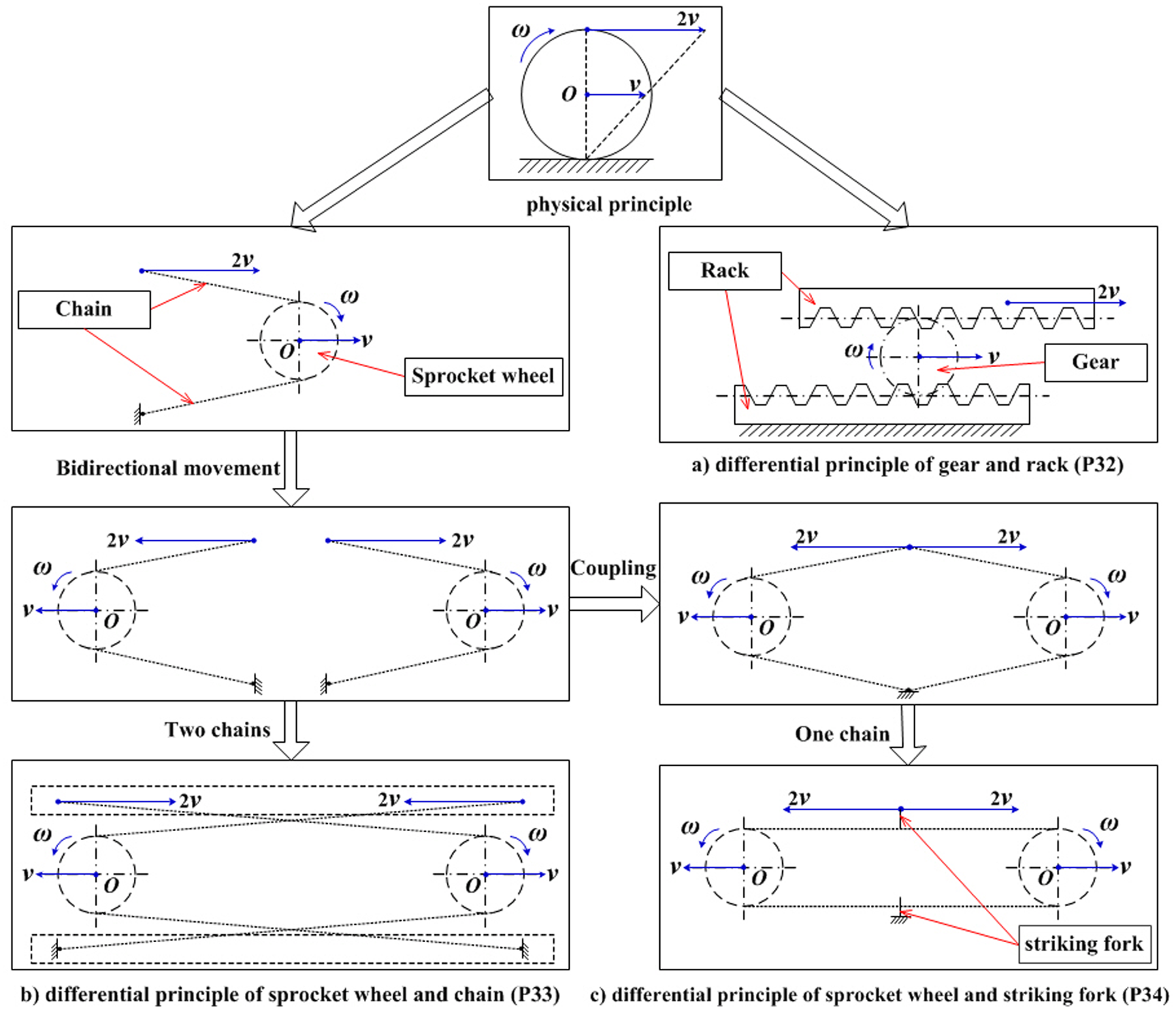
The generation process of three typical triple-differential principles.
There are two kinds of relations between the design elements nodes in Figure 8. One is the mapping relation, from which the mapping frame of the design process can be established. Another is the logic relation, namely the ‘and/or’ relations among the design element nodes, which exhibit the connection relation among the nodes of the mapping frame. Since P32, P33 and P34 can all achieve the required function F36, there are ‘or’ relations among them.
Working principle elements
Different solutions will be established by solving the three working principles respectively. P32 is mapped to two multiple behaviours: ‘gear engages with two racks simultaneously’ (B35) and ‘upper layer moves at diploid speed’ (B36). In addition, P33 is mapped to two behaviours: ‘two chains engage with one sprocket wheel and two holding fixtures respectively’ (B37) and B36, while P34 is mapped to two behaviours: ‘one chain engages with two sprocket wheels simultaneously’ (B38) and B36.
Behaviour elements
B35 is actually a behavioural process that is comprised of some simple behaviours with temporal and causal relations. Three simpler sub-behaviours are obtained from B35 by using DecMP, including ‘under rack holds still (v0 = 0, s0 = 0)’ (B41), ‘motion of gear (v1, s1)’ (B42) and ‘motion of upper rack (v2=2v1, s2=2s1)’ (B43). In the same way, B37 is decomposed into three sub-behaviours: ‘motion of sprocket wheel (v1, s1)’ (B44), ‘motion of chain’ (B45) and ‘motion of holding fixture (v2, s2)’ (B46), while B38 is decomposed into four sub-behaviours: B44, ‘motion of chain’ (B47), ‘under striking fork holds still (v0 = 0, s0 = 0)’ (B48) and ‘motion of upper striking fork (v2, s2)’ (B49).
Structure elements
Structures are the ultimate mapping targets of the conceptual design process. B41∼B49 are all simple behaviours that are mapped to S41∼S49 in turn by the mapping B→S. B36 is also simple and is mapped to S23.
As discussed above, the structures of F36 are S41∼S49 and S23, which are satisfactory and do not need any further process. The diagrams of these three design solutions to F36 are shown in Figure 10.
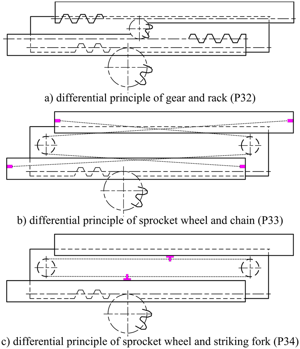
The diagram of three design solutions to function F36.
According to the flows of function solving, principle solving, behaviour solving and structure solving, all design elements nodes are accomplished, that is to say, every solving route branch terminates in the S→Ф operation. During the design process, the supportive strategies, such as performance match analysis, behavioural compatibility analysis and structural compatibility analysis, are performed to verify the design solutions. Several feasible concepts that can meet the design requirements are generated in the conceptual design stage, from which the final products are formed through further development.
In order to better exhibit the design results of the aforementioned process, a detailed structure is given for each functional structure in Figure 8. Moreover, Figure 11 shows the exploded view of the telescopic shuttle mechanism achievement by P32. Figure 12 shows its three-dimensional assembly drawing.
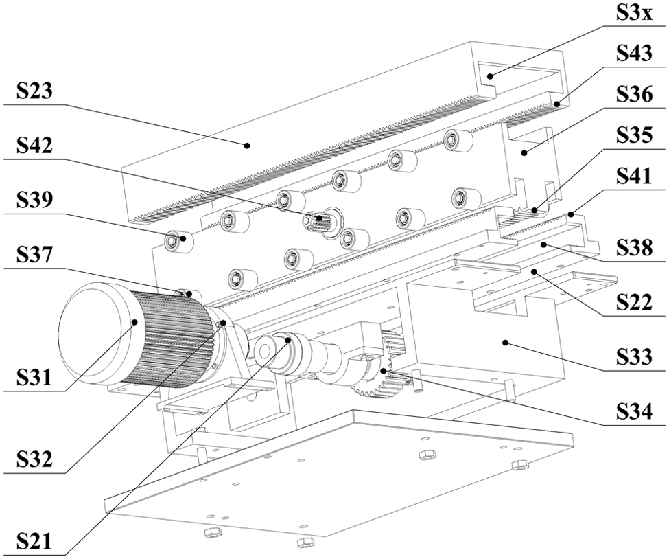
Exploded view of the telescopic shuttle mechanism.
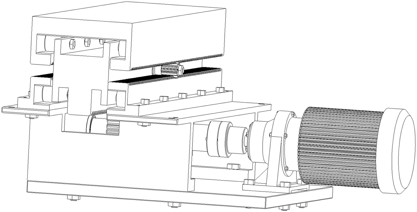
Assembly drawing of the telescopic shuttle mechanism.
Software prototype
To assist designers to implement the proposed framework, a software prototype ‘conceptual design tool (CDT)’ is developed. We use Delphi as the development platform, which is an object-oriented visual programming environment. The graphical user interface of CDT is shown in Figure 13. With this tool, the designer can carry out a design synthesis and the whole design process shall be recorded. Various nodes are used to represent the design elements, including the function node, the working principle node, the behaviour node and the structure node. Meanwhile, various lines are used to represent the mapping relations between design elements. The function node is labelled with a letter ‘F’, while the working principle node is labelled with a letter ‘P’, the behaviour node with a letter ‘B’ and the structure node with a letter ‘S’.
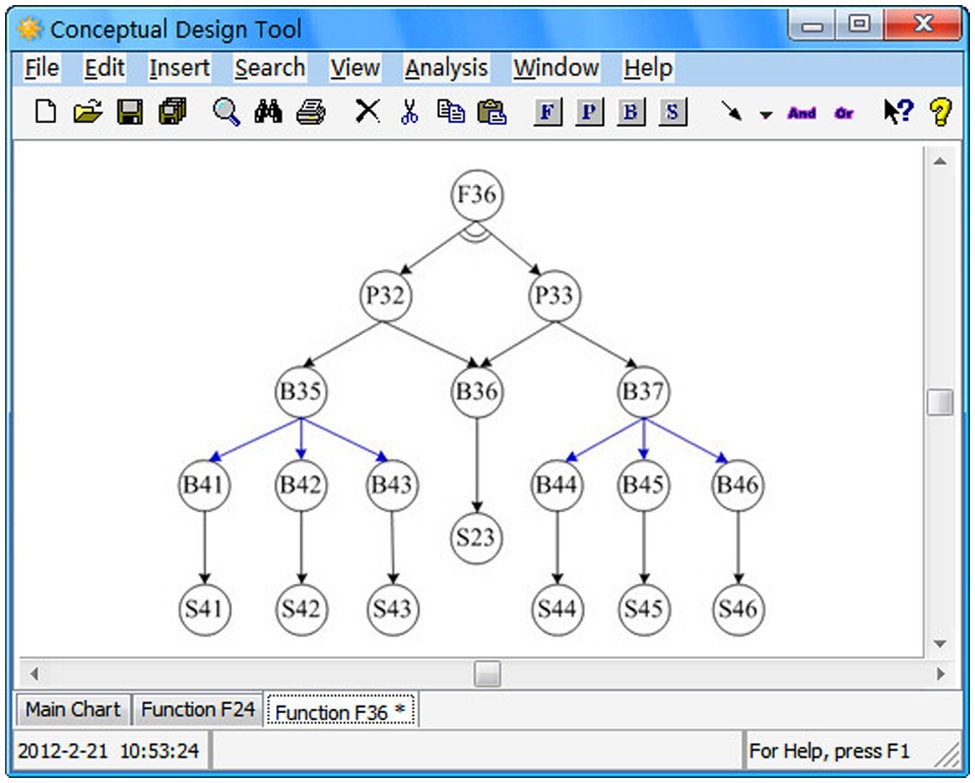
Graphical user interface of CDT.
As shown in Figure 13, there are three tab sheets, including the ‘Main Chart’ tab sheet, the ‘Function F24’ tab sheet and the ‘Function F36’ tab sheet, which represents the design process starting from different function nodes. By using CDT, the design process is always starting with a selected node. A pop-up menu, offering several operations, will be activated by right-clicking the mouse on that node. The blank area is reserved for drawing a design ‘and/or’ tree.
Figure 14 shows the implementation procedure of CDT that includes seven steps. The procedure starts with inputting the overall function node, which is followed by searching the knowledge libraries automatically. In the second step, the design knowledge libraries can be searched to assist the designers to find design solutions. The system is designed to search the libraries subsequently in accordance with the priorities of the mapping relations elaborated in ‘Mapping evolutionary logic’. The third step is to solve the design nodes automatically/manually. If one or more records are found in all libraries, then the mapping relations are activated, whereby the relevant nodes will be created and added to the design ‘and/or’ tree automatically. If no record is found, various mapping methods can be applied to solve the design nodes manually, depending on the experience of designers. Having finished that, we come to the fourth step, where we build up the whole design ‘and/or’ tree. Then all the design solutions are generated automatically in the fifth step. The tool can extract all the design solutions from the full design ‘and/or’ tree automatically by distinguishing the ‘and/or’ connections. After that, we verify each design solution based on rules in the sixth step. Some unsatisfactory solutions need to be deleted by applying the rules described in ‘Rules in verifying design solutions’, and the remainders are feasible. In the last step, we specify the optimal design solution manually. The designer can choose the best one from the remainder.
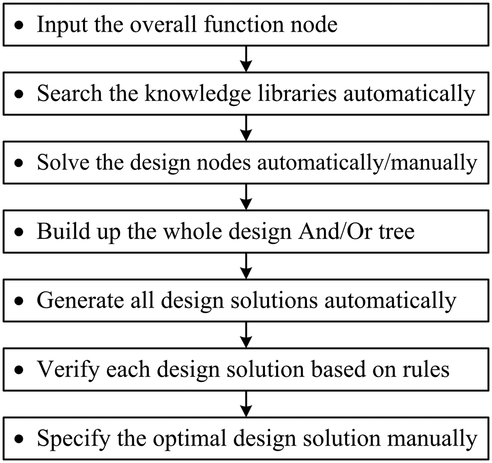
Implementation procedure of CDT.
Conclusions
This research puts forward a new hierarchical functional solving framework for the conceptual design. The framework is achieved by hybrid mappings among four design domains: function, working principle, behaviour and structure, including four mapping patterns and 15 basic mapping relations. The purposes of this study are threefold. First, this work aims to provide a better understanding of the way in which designers actually design. Second, this work seeks to provide the right means to system developers for building computer tools. And finally, we intend to aid designers and to automate some of the conceptual design tasks. The advantages and contributions of the research are defined as follows.
The framework extends the product information represented by extracting the way of function achievement and adding its essential attribute ‘working principle’ to the design domain set.
The mapping relations are enriched by taking into account experiential knowledge of the designers. All mapping relations can be categorized into four patterns.
The framework helps to integrate inheritance with innovation by establishing rational design domains, hybrid mappings relations and mapping evolutionary logic.
The framework can effectively improve the ability of the conceptual design by combining the creative thinking of designers with the power of reasoning computing of computers.
The procedure of applying the FPBS framework to the conceptual design and corresponding supportive strategies are discussed in ‘Conceptual design based on FPBS framework’. By accomplishing the flow of the conceptual design process, a hierarchical ‘and/or’ graph of the design result, namely the functional solving process model, will be generated, including several feasible design solutions. The functional solving process model represents a part of (but not all of) the design rationale, that conduces to better design understanding among system architects and engineers.
The framework has already been applied, tested and validated empirically. This work may be developed further in the future in the following ways.
The software prototype given in ‘Software prototype’ has not been completed yet, which should be further developed, applied and improved in practice.
The concrete applications of the strategies to verify design solutions, such as performance match, behavioural compatibility and structural compatibility should be studied.
An adaptation to the FPBS framework should be made by incorporating environmental constraints into the design process so as to further enhance the mapping relations and evolutionary logic of the design elements.
The FPBS framework and other previous functional solving models pay more attention to the process of decomposition and solving, but ignore the inter-relationships among design elements. Erden et al. have developed a Petri net-based design inference network (PNDN) architecture to model the logical behaviour of products by representing the sub-functions and their inter-relationships to perform a required function. 23 We will try to integrate the FPBS framework with that of the PNDN in order to further improve the validity of the application of the framework.
Footnotes
Funding
This work was supported by the Departmental Pre-Research Fund of China, project number is 9140A18010210KG01.