
Abstract
The bending moment exerted to the forging manipulator induced by the press motion during the metal forming process is investigated. The manipulator system, including the manipulator and the workpiece, is modelled as a single degree of freedom system oscillator with displacement excitement. The Winkler foundation is used to simulate the rotational constraint of the forging dies on the workpiece because of the surface contact. The closed solution of the dynamic bending moment in time domain is obtained, a useful design formula is derived that explicitly shows the dependence of the bending moment amplitude on the relative parameters, including the press position, clamp mass and compliance stiffness. The analytical results are compared with the commercial finite element software simulations, and good agreements could be observed. The results indicate that the press position where the forging dies act on the workpiece plays a crucial role to the dynamic bending moment. The maximum bending moment increases with the increase of clamp mass and compliance stiffness.
Introduction
Open die forging is a key process for producing shafts, stators, rotors and other important mechanical components. This manufacturing technology remains highly labour intensive despite low productivity, high costs and hazardous working environments. In order to improve working efficiency and reduce human burden, the forging manipulator is usually provided as an auxiliary tool in the forging workshop to serve the hydraulic press.
For the forging press with conventional construction, the lower die of the press is fixed during the forging process, while the upper die carries out the working stroke. As a result, the middle axis of the workpiece unavoidably moves downwards during the shaping, and the forging manipulator has to follow the movement of the workpiece axis. This following movement produces huge interface force and bending moment between the manipulator and the workpiece. An excessive force will cause damage to the mechanical structure of the manipulator. Compared with the dynamic force, the bending moment is more important for the workpiece, which could potentially cause plastic bending of the workpiece at the clamping point. For example, Schey and Abramowitz 1 reported that a rectangular aluminium bar of 25 mm by 90 mm section could be bent easily with light hand pressure on the free end as it was being forged at normal temperature.
To reduce the interface dynamic loads as much as possible, a compliance system is provided in manipulator design. Active control strategies have been attempted on the compliance system. Lilly and Melligeri 2 introduced the neural network control method to minimize the interaction force; the dynamic simulation was executed by the efficient O(N) recursive algorithm. Nye et al. 3 presented a novel method to predict the spread coefficient of the workpiece by using a real-time process feedback signal, which was expected to be applied in the intelligent open die forging system. A few other investigations4–7 focused on the fast computation of the plastic deformation of the workpiece for facilitating the real-time control. Obviously, active methods can provide the manipulator with a high degree of versatility. However, measurement errors will inevitably arise in the vibrating and noisy forging workshops, which definitely degrade the manipulator performance for these sensor-based methods. A semi-active strategy 8 was patented by the Pahnke Company of Germany: the manipulator is adjusted to match the movement of the upper die of the hydraulic press by the simultaneous communicating time signal; but this method is only applied to their own forging system so far. Nowadays, the passive compliance design is still popular in the forging industry owing to its reliability, which is important in the harsh forging conditions. It works through using an air spring component9–11 to provide the manipulator with a soft cushion. Yan et al. 12 analysed the interaction force using a static stiffness model, the dynamic effects induced by the press motion were ignored. Liu et al. 13 investigated the influence of the compliance parameters on the maximum value of the interface force when the manipulator underwent a large motion. A multi-system simulation methodology was suggested by Wang et al., 14 in which the finite element analysis of the workpiece forming and kinematics analysis of the manipulator were combined to calculate the interaction loads. Chen et al. 15 analysed the force using the commercial finite element program Deform-3D.
The scope of this article is focused on the bending moment transmitted to the forging manipulator gripping a slender workpiece, which serves the hydraulic press in the forging process with passive compliance. Clearly the calculation of the moment is complicated in this press–workpiece–manipulator integrated system. The dynamic response of the manipulator is coupled with the press motion and plastic deformation of the workpiece. Although several of the models mentioned above12–15 have been proposed to describe what is going on with the manipulator during the metal forming process, less attention has been paid to the possibility that the manipulator system may vibrate owing to the press motion, which could probably influence the dynamic characteristic of the system. This article describes a single degree of freedom (SDOF) model to predict the press motion induced response of the manipulator system. The effects of vibration are taken into consideration and the dynamic bending moment transmitted to the manipulator is calculated in closed form. The bending moment amplitude is derived in terms of relative parameters, including the press position, clamp mass and compliance stiffness. Comparisons between the analytical results and the commercial software LS-DYNA simulations are made to validate the proposed model. Theoretical explanations are provided to explain how the above parameters influence the bending moment amplitude.
Description of the forging manipulator system
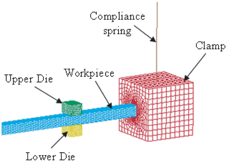
Figure 1 shows a typical integrated press–workpiece–manipulator system. The workpiece (3) is held by the clamp (4) of the manipulator, and is deformed into the desired shape between the two dies (1) and (2) of the hydraulic press. The parallel planar parts (5), (6), (7), (8) and (9) are designed to manoeuvre the clamp (4) and keep it horizontal.
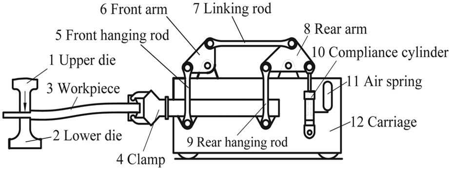
The integrated press–workpiece–manipulator system.
There are four stages in one forging stroke for a conventionally designed forging press, which are the empty down period, compression period, decompression period and upstroke period, respectively, as plotted in Figure 2(a). During the empty down period, the upper die (1) first falls quickly and then slows down to the upper surface of the workpiece (3). In this period, the manipulator system is at rest, no contact force occurs between the forging dies and workpiece. Then the metal compression begins, the upper die (1) squeezes the workpiece (3) against the lower die (2) until it reaches the desired position. The forging manipulator has to move down with the workpiece against the restored force in air spring (11). Then the upper die (1) remains stationary at the position before the return stroke, and the manipulator system experiences a free vibration during this decompression period. Finally, the forging manipulator returns to the original working position after the upper die goes back during the upstroke period. After that, the next forging stroke will be executed at another position of the workpiece. One forging pass comprises several working strokes to forge the whole workpiece to the prescribed thickness as shown in Figure 2(b). This article mainly concerns the contact operation period, which compromises the compression period and decompression period.
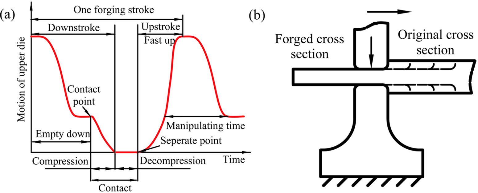
(a) Upper die motion; (b) working strokes in one forging pass.
In practice, the forging clamp (4) is much heavier than the linkage parts, and the manipulator system could be modelled as shown in Figure 3 in this study. The variables kc and mc represent the compliance stiffness and clamp mass, respectively. The rotational degree of freedom of the clamp is fixed owing to the constraint of the planar parallel linkage. A rigid connection is defined between the workpiece and clamp at point O1.2,12,13 The rectangular bar workpiece is selected for the present analysis, which was usually taken as the study sample in relative investigations.2–7,12 Point O2 is located at the centre of the forging section (shadow area), which endures the plastic forming.
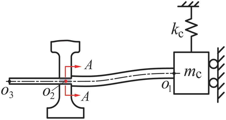
The simplified model of the forging manipulator system.
During the plastic deformation, displacement distribution of the workpiece along the height direction in cross-section A–A (through point O2, Figure 3) is plotted in Figure 4(a). The movement of the top point OT is identical to that of the upper die. Since the lower die is fixed, the displacement of the bottom point OB is equal to zero. A linear distribution of displacement could be assumed along the height 16 for the rectangular section, which indicates the displacement of the central point O2 is half of the movement of the upper die. This movement of point O2 will induce the transient vibration of the manipulator system. Then the manipulator system can be modelled as a cantilever beam on a moving point, with a compliance spring at the heavy sliding tip, as shown in Figure 5. The constraint of the forging dies on the rotational freedom of point O2 owing to surface contact is considered as a torsional spring (the detail will be discussed in the section ‘The rotational constraint of the forging dies on the workpiece’). The length l of section O1O2 is defined as the press position, which is used to locate the position where the forging dies act on the slender workpiece. Obviously, the variation of the press position l will change the vibration characteristic of the manipulator system.
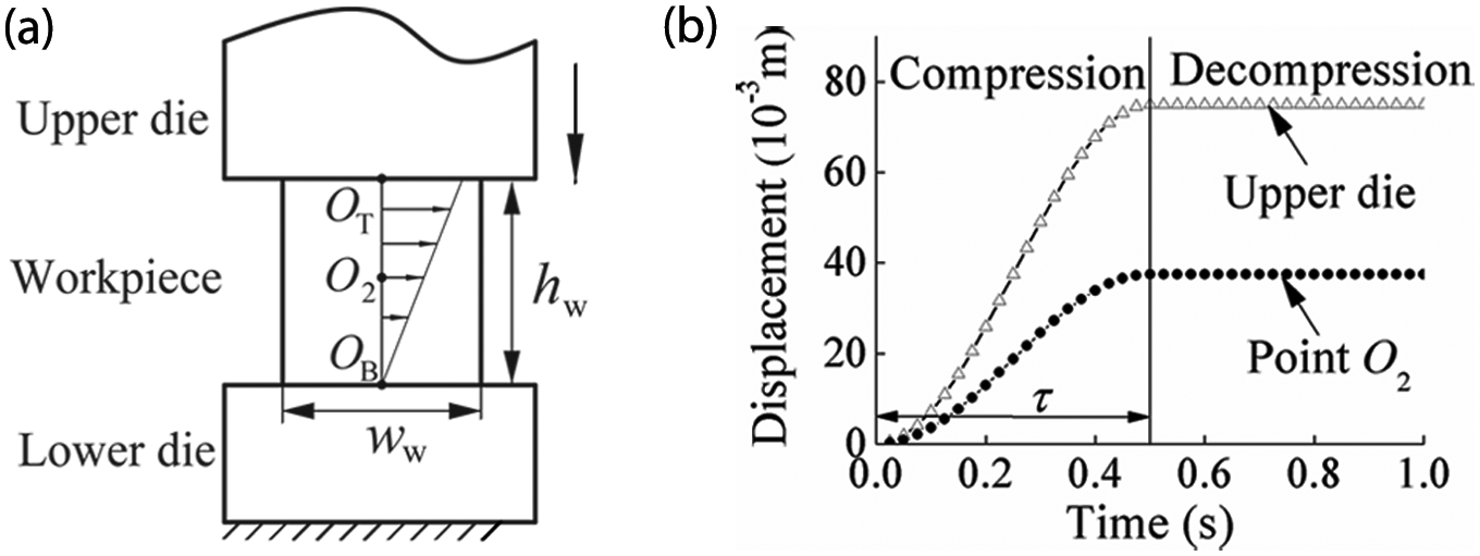
(a) Vertical displacement distribution in section A–A along the workpiece height; (b) motion curves of upper die and point O2.
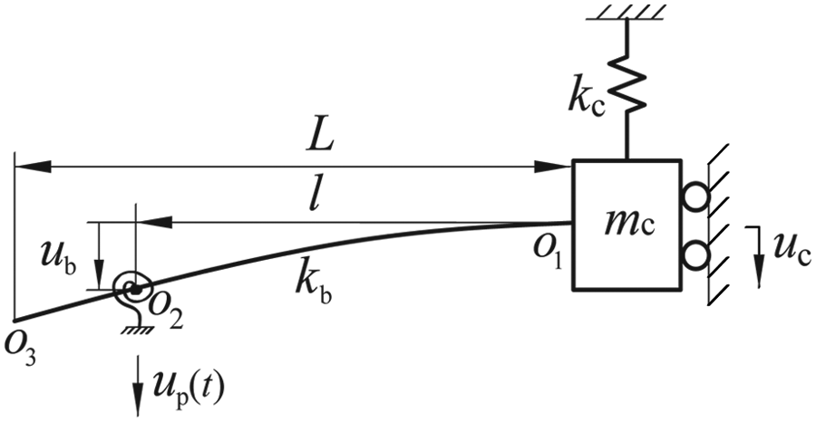
SDOF dynamic model of the forging manipulator system.
Normally the motion of the hydraulic press is well programmed, which means the displacement–time function of point O2 is given. In the present article, a versed sine front function is used to describe the motion of point O2 during the contact operation period, as shown in Figure 4(b), the mathematical formulation is written as
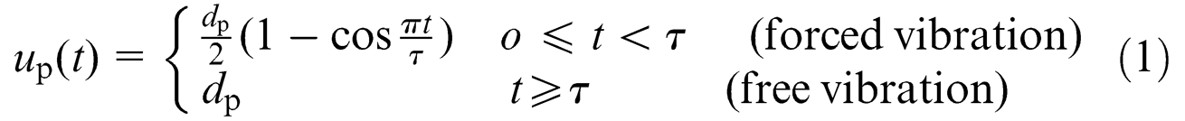
where τ = 0.5 s is the duration of the compression period, and dp = 37.5 m−3 is the movement amplitude of point O2. Obviously, the system is subjected to a forced vibration during the compression period and a free vibration during the decompression period.
Dynamic model of the forging manipulator system
The rotational constraint of the forging dies on the workpiece
The forging dies will prevent the workpiece from rotating to some extent because of the surface contact stresses between them. The description of the contact model shown in Figure 6(a) is based upon the simplest theory that is appropriate: the Winkler foundation. This model has been widely used in soil–structure interaction (SSI) analysis. 17 The following assumptions are made for the present analysis.
Only elastic surface contact occurs owing to the workpiece rotation, although this section undergoes plastic deformation at the same time.
The forging dies are considered rigid bodies.
The bending flexibility of the workpiece in this short section is ignored.
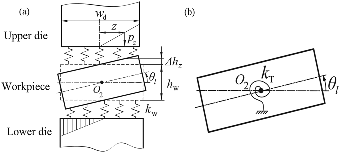
(a) The Winker surface contact model; (b) the equivalent torsional spring model.
Taking the surface contact between the upper die and workpiece for example, in the Winkler model, a series of springs is arrayed along the contact surface, and the contact stiffness per length unit kw is calculated as

where E is the Young’s modulus of the workpiece, ww and hw are the width and height of the workpiece (Figure 4(a)), respectively. It is noticed that only half the surface of the workpiece contacts the upper die, because the other half has been uplifted owing to rotation of point O2. The contact pressure pz at the position z is written as

where Δhz is the elastic deformation of workpiece at position z, θ l is the rotational angle of the workpiece. The lower die is assumed to be the same as the upper die. Considering both of the dies, the total moment exerted to point O2 could be written as

where wd is the width of the forging die.
Figure 6(b) shows the equivalent model used in this analysis; the Winkler model has been substituted by a torsional spring placed at the centre of point O2, whose stiffness is determined by

The stiffness of the slender workpiece
In statics, if the reactions and internal forces of a structure could be determined solely from the equations of equilibrium, it is called a static determinate structure. On the contrary, if the static equilibrium equations are not sufficient for determining the internal forces and reactions, the structure is statically indeterminate, and the analysis requires additional equations based on the deformation of the structure. As for the beam workpiece in the present analysis, the cantilever beam would be a static determinate if all the constraints on the point O2 were removed. However, two constraints do exist at point O2, which are the displacement constraint of O2 and the rotational constraint of the torsional spring, respectively. So the workpiece is statically indeterminate. To solve the static indeterminacies, the structure has to be reduced to the statically determinate structure by removing the redundant constraints, which are replaced by the reaction force F1 and moment M1, respectively, as shown in Figure 7(b). Suppose there is a unit deflection 1 at the point O2 of the workpiece, and θ1 is the rotational angle of beam at point O2 induced by the unit deflection 1, as shown in Figure 7(a). The reactions could be obtained by using the slope deflection method 18


where
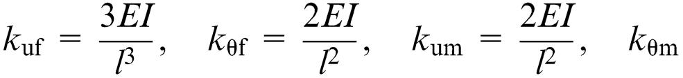
where kb is the bending stiffness of the indeterminate beam, which heavily depends on the press position l.
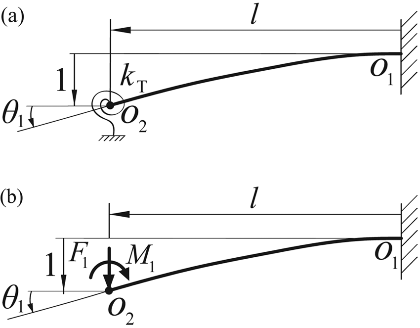
(a) The statically indeterminate beam to analyse; (b) the primary structure with reactions.
The bending moment imposed on the manipulator owing to the unit deflection 1 could be expressed as

Dynamic equations of the manipulator system
As shown in Figure 5, the displacement of the clamp uc could be expressed as

where ub is the deflection of the beam at point O2.
By applying the Newton’s second law to the clamp mass mc

Substituting equation (9) into equation (10) and rearranging the results, the dynamic equation of the SDOF system could be expressed as

where k is the stiffness of the manipulator system, which is the sum of the workpiece stiffness and compliance stiffness


The general solution of equation (11) can be obtained by solving the Duhamel’s integral, which is used to evaluate the response of a SDOF oscillator to any form of dynamic loading. The dynamic deflection could be expressed in the standard form 19

where

is the response to a unit impulse,
During the forced vibration period 0 ≤t≤τ, the deflection ub is written as
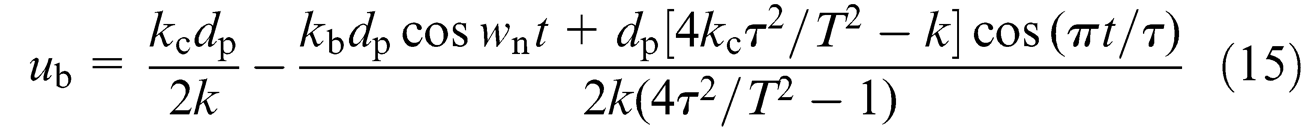
where
If the maximum transient deflection of the workpiece occurs during this phase, the time point at which the maximum response occurs can be determined by
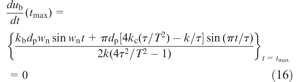
Equation (16) represents an implicit function of tmax, which can be solved by the numerical method. The maximum deflection ub,max could be obtained by substituting the solution into equation (15).
During the free vibration period t≥τ, the deflection ub could be expressed as
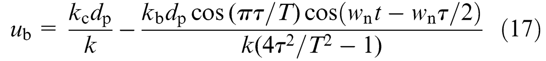
The time of maximum deflection could be obtained by differentiating equation (17) to t, equating the result to zero and solving t. The result is
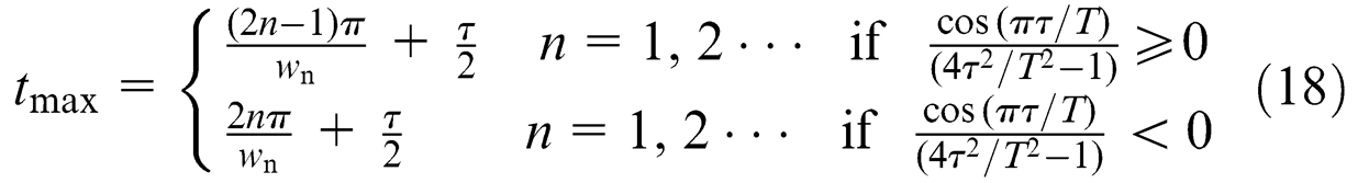
For both cases of equation (18), the maximum deflection could be expressed as
It can be seen from the above deviation that there is more than one time point corresponding to the maximum deflection. So the time point tmax for the maximum deflection is defined as that when the deflection first reaches the maximum value in the time domain.
In consideration of equation (8), the bending moment transmitted to the manipulator is written as

The maximum bending moment in time domain is expressed as

Obviously, the maximum bending moment Mmax occurs at the time point tmax just as the maximum deflection ub,max.
Results and discussion
Verification of the proposed SDOF dynamic model
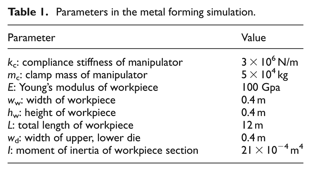
The finite element method (FEM) is highly recognized for its ability to accurately simulate the forming processes, which is widely used in metal forming.20–22 To verify the SDOF dynamic model of the present article, the metal-forming process is numerically realized in the commercial finite element software LS-DYNA. 23 The three-dimensional finite element model of the manipulator system is shown in Figure 8. The lower die is fixed and the system is initially at rest. When the metal forming begins, the upper die presses the workpiece against the lower die with the motion curve shown in Figure 4(b). The elastic perfectly plastic material model is used for the workpiece. The corresponding simulation parameters are listed in Table 1. The compliance spring is simulated by the element COMBI165, all the other parts are divided by the SOLID164 elements. The COMBI165 element is a two-node one-dimensional element, which acts like a simple tension spring. The force is generated along the axis between the two nodes, the value depends on the change of length of the element. The SOLID164 element is an eight-node three-dimensional brick element with three degrees of freedom at each node in X, Y, and Z directions. The reduced one-point integration is used in this element, which has the advantage with the fastness and robustness of numerical calculation in cases of large deformation, like metal forming.
Three-dimensional FEM of the forging manipulator system in LS-DYNA.
Parameters in the metal forming simulation.
The yield stress of the material is an important factor that influences the plastic shaping process. Figure 9 shows the variation of yield stress with temperature for several carbon and alloy steels that are usually forged in an open die forging process. It can be seen that the yield stress is different for different steels, even for the same steel, the yield stress changes as the temperature changes during the forging process. In order to make the LS-DYNA model more realistic, the yield stress is taken into consideration. Three values of yield stress in Figure 9 are selected for the LS-DYNA simulation, which are the maximum value σs = 300 MPa (1Cr18Ni9Ti at 850 °C), the minimum value σs = 51 MPa (9CrSi at 1150 °C) and an intermediate value σs = 140 MPa, respectively.
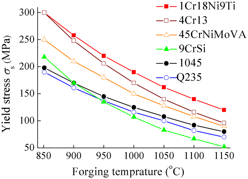
Variation of yield stress with forging temperature for different steels.
Figure 10 shows the bending moment histories at different press positions for the SDOF model and LS-DYNA models with the three yield stresses. Generally, the proposed SDOF model slightly overestimates the vibration frequency of the system compared with the LS-DYNA models, while all the four models agree well in the trends and the peak values. The comparison also indicates that the influence of the value of yield stress is slight, which could be explained by two reasons. First, the dies only plastically deform the localized region of the workpiece in the die–workpiece contact zone, while other region of the workpiece remains elastic. 12 For example, Figure 11 graphically shows the plastic fields of the workpiece for three different press positions, with the yield stress σs = 51 MPa at the time point t = 0.3 s. It can be noticed that the plastic shaping concentrates in the contact zone at each press position, which indicates that the yield stress has minor influence outside of the plastic deformation region. Second, in the local plastic region, the influence of the plastic deformation on the manipulator system is that it produces the node (point O2) motion of the workpiece. In the contact zone, the displacement of the top surface of workpiece is equal to that of the upper die, and the displacement of bottom surface is zero because the lower die is fixed. At the same time, since the geometry of the rectangular cross-section A–A is symmetric, as well as the material is isotropic and homogenous, the deformation of this cross-section is always symmetric about the central point O2 from top to bottom, regardless of elasticity or plasticity. As a result, the displacement of central point O2 is half of the displacement of the upper die. For instance, Figure 12(b) compares the motions of the nodes of point O2 (see Figure 12(a)) with different yield stresses at the press position l = 3 m. It shows that all the three motions perfectly coincide with equation (1), which indicates that the motion of point O2 is determined by the motion of the upper die independent of the yield stress. So, based on the above two reasons, whatever is inside or outside the plastic deformation region, the influence of yield stress is insignificant; the proposed model is available for different yield stresses.
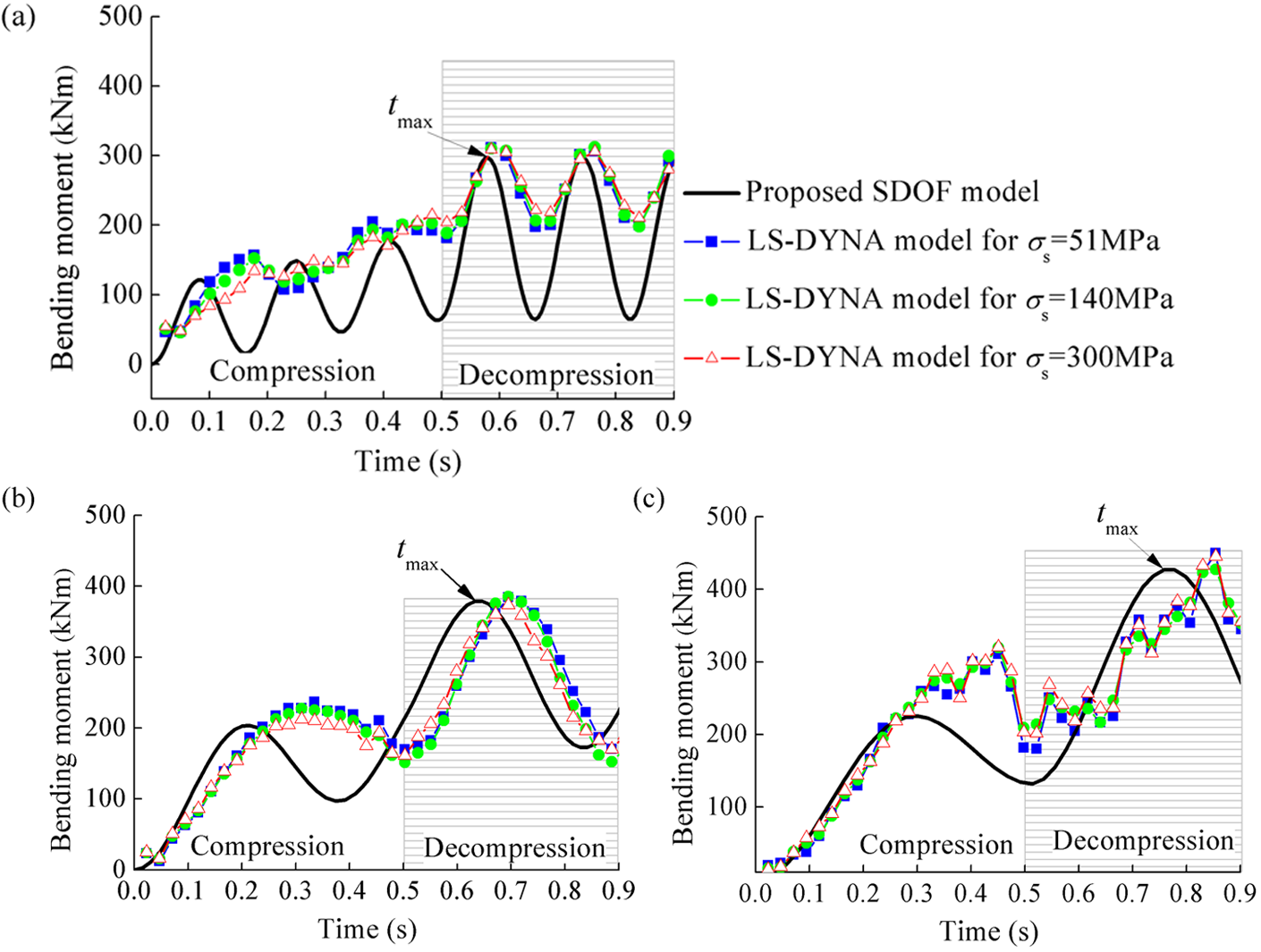
Dynamic bending moments transmitted to the manipulator for different press positions: (a) l = 3 m; (b) l = 6 m; (c) l = 9 m.
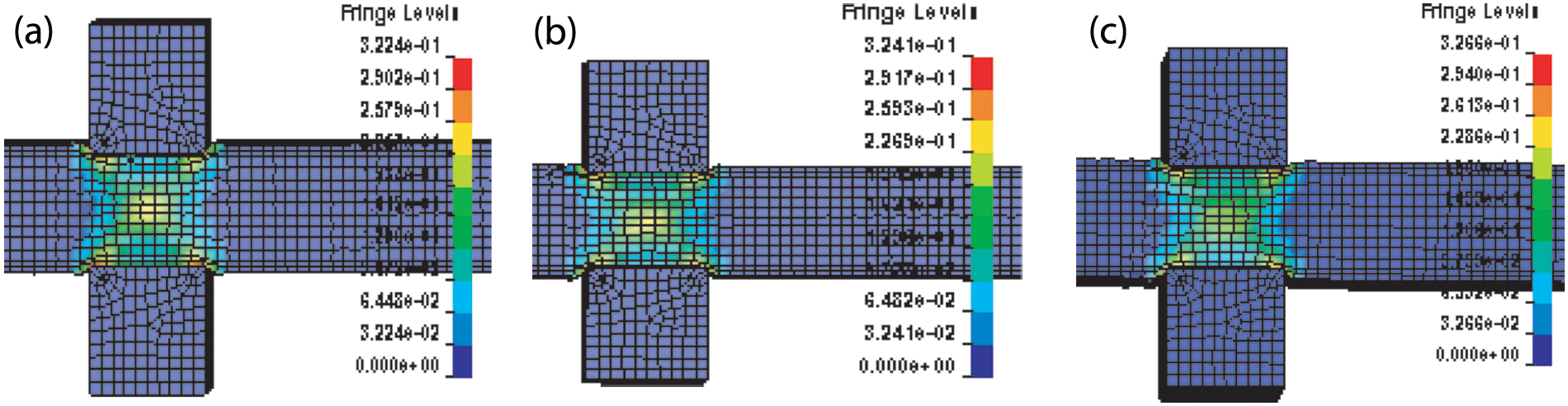
Plastic fields of the workpiece at three different press positions, with σs = 51 MPa, t = 0.3 s. (a) l = 3 m; (b) l = 6 m; (c) l = 9 m.
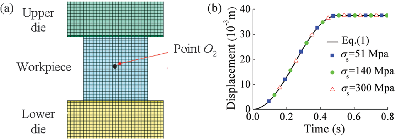
(a) Node at point O2 in LS-DYNA model; (b) motions of nodes at point O2 for different yield stresses at l = 3 m.
The following observations can be further made.
The vibration frequency increases with the decrease of the press position l. That is because the beam section O1O2 between the press and the manipulator becomes stiffener when it shortens, as shown in Figure 13.
All the time points tmax corresponding to the maximum moments are in the decompression period (shadow area) for all the three press positions, but the values are different. This observation modifies the conclusion in Yan et al., 12 that the maximum moment takes place at the end of the compression period. Because the vibration effects of the manipulator system owing to press motion are ignored in the static model, the maximum moment will happen at the end of the metal compression period, when the compliance spring reaches the maximum deflection, which neglects the possibility of other time points.
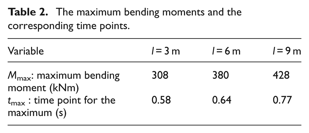
The values of the maximum bending moments are different for different press positions, which are listed in Table 2 together with the corresponding time points.
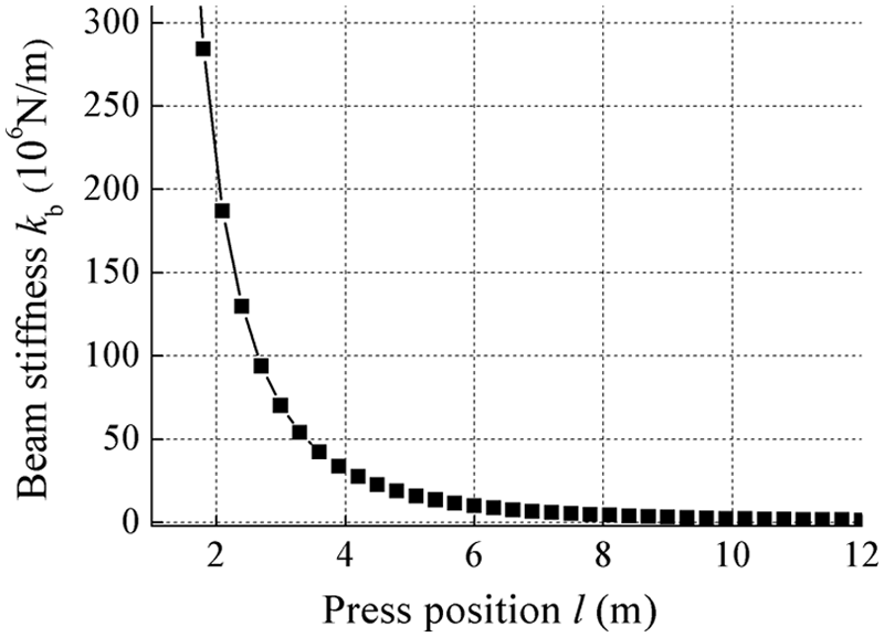
Variation of beam stiffness kb with press position l.
The maximum bending moments and the corresponding time points.
Effects of the press position on the maximum bending moment
Figure 14 shows the maximum bending moments at different press positions for the SDOF model and LS-DYNA models. To quantitatively assess the performance of the proposed SDOF model, two statistical measures of accuracy were applied to evaluate the overall agreement between the curve of the SDOF model (equation (21)) and the LS-DYNA points. The coefficient of determination (R2) 24 describes the proportion of the total variance in the observed data (LS-DYNA) that can be explained by the prediction model (SDOF) in regression. It provides a measure of how well the values of LS-DYNA are likely to be predicted by the SDOF model. R2 ranges from 0 to 1. A value of 1 indicates a perfect fit, on the other hand, a value of 0 would indicate that the SDOF model fails in prediction. The expression of R2 is written as
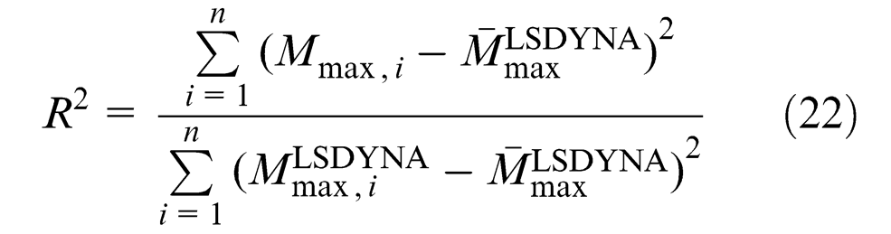
where
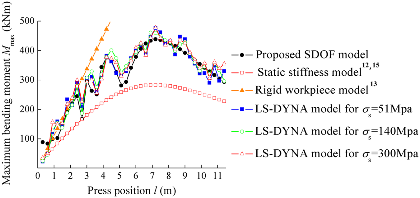
Variation of maximum bending moment Mmax with press position l.
Another measure is the % standard error of prediction SEP%, which is defined as
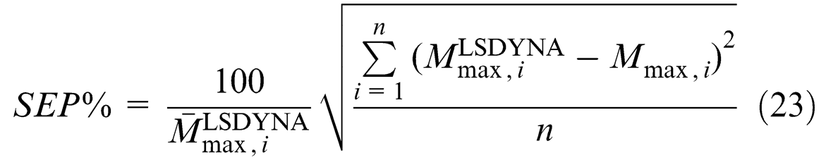
It reflects the degree to which the observed data (LS-DYNA) diverges from the prediction model (SDOF). For a perfect match, the value of %SEP is equal to zero.
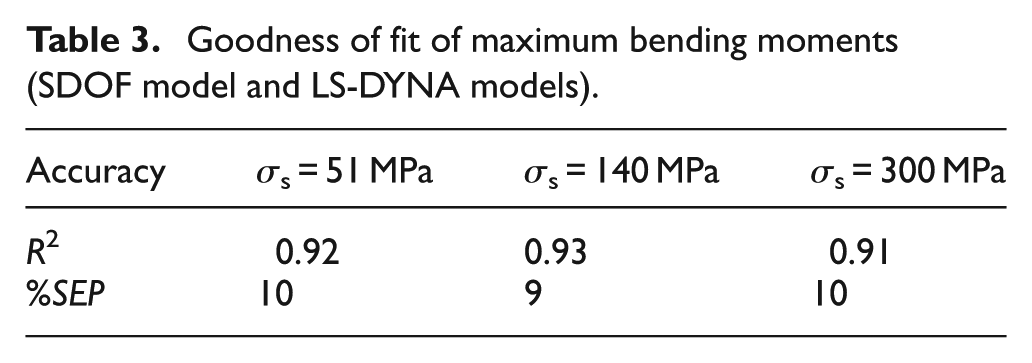
Table 3 shows the goodness of fit between the SDOF model and the LS-DYNA models with different yield stresses. The minimum value of R2 is 0.91, which means that at least 91% of the LS-DYNA points could be explained by the curve of the SDOF model. The maximum value of %SEP is 10, which indicates that less than 10% of the LS-DYNA points diverge from the proposed curve. The accuracy is satisfactory. But the proposed SDOF model is computationally more efficient than the finite element model. In using the finite element code to obtain the maximum bending moment at one press position, it will take about 2 h. As for the 40 finite element simulations to describe the trend of the maximum bending moment with the press position, 80 h are needed. However, if the proposed SDOF model is used, the results could be obtained instantly as long as equation (21) has been established, in which the maximum bending moment is expressed as the continuous function of the press position. This is important, especially for the preliminary design.
Goodness of fit of maximum bending moments (SDOF model and LS-DYNA models).
It can be noticed from Figure 10 that Mmax begins as an increasing function of the press position l except at some local peaks. Then, after reaching a maximum peak, it decreases with the increase of the press position l.
The time points for the maximum bending moments are plotted in Figure 15. An interesting observation could be made that all the maximums occur in the decompression period. This is not surprising, because for the step-style excitation Fu(t) of equation (13) in the present analysis, as shown in Figure 16, in the case of the step-type excitation, the maximal response always occurs after the excitation has reached its constant maximum value, and it is related to the residual response amplitude. 25 The rest of the article will focus on the decompression period.
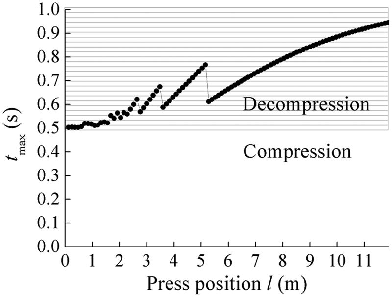
The time points when the maximum bending moments take place.
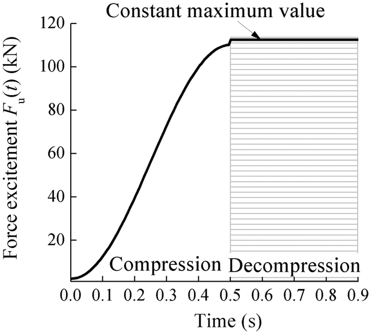
Time history of excitation force Fu(t).
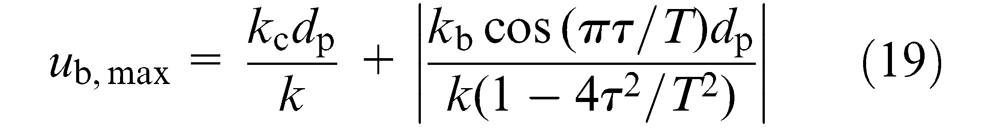
Figure 17(a) shows the variation of the maximum deflection of workpiece ub,max with the press position l. It can be observed that, generally, ub,max increases along with the press position l, which could be roughly explained as follows. The workpiece stiffness kb decreases with the increase of press position l as discussed before, resulting in the increase of the natural period T of the system. The increase of T causes a decrease of the term

in equation (19). In spite of the marginal decrease of kb/k owing to the decrease of kb, the second term still increases. Also, the first term kc/k in equation (19) increases with the decrease of workpiece stiffness kb. Thus, both terms in equation (19) increase with the increase of press position l, which results in the increase of the maximum deflection ub,max.
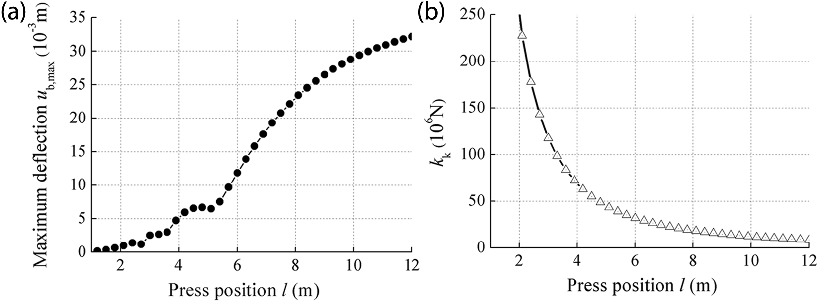
(a) Variation of ub,max with press position l; (b) variation of kk with press position l.
On the contrary, kk (equation (8)) decreases with the increase of press position l, as shown in Figure 17(b). Now it is known that the increasing–decreasing trend of Mmax actually stems from the multiplication of the increasing function ub,max and the decreasing function kk, according to equation (21). As a result, the maximum value of Mmax occurs at the middle span of the workpiece. In one forging pass, the forging dies could possibly work at any press position, as shown in Figure 2(b). This maximum value of Mmax all over the workpiece length is of primary importance, which is termed as global maximum bending moment
The comparison with some previous works is also plotted in Figure 14. The similar trend could be observed for the static stiffness model12,15 in the variation of the maximum moment Mmax. But because the dynamic effects owing to press motion are not considered, the maximum moments are underestimated at all the press positions, especially those corresponding to the peaks in the proposed SDOF model. The global maximum moment is
If the workpiece is regarded as a rigid body,
13
a linear relationship could be seen between the maximum bending moment Mmax and press position l, because the bending moment at the clamp point is proportional to the moment arm l for a rigid bar. The maximum moment Mmax will be always overestimated where l≥ 1.75 m, when the press becomes farther away from the clamping point. The global maximum
The effects of the design parameters of the manipulator on the maximum bending moment
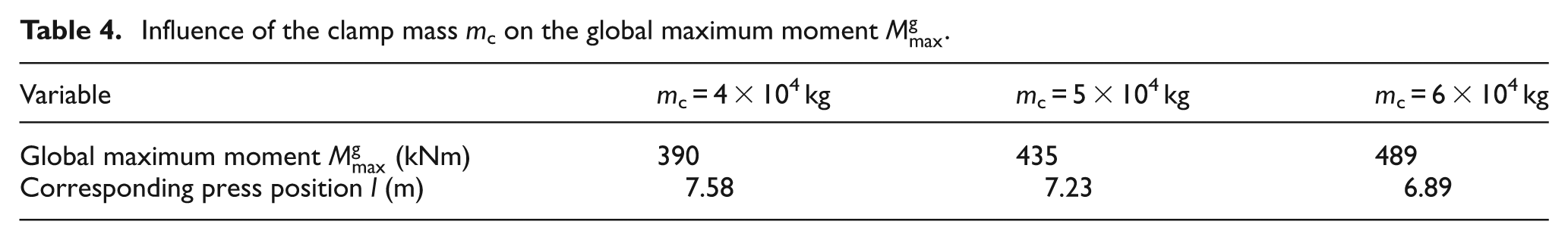
The effects of clamp mass mc on the maximum bending moment Mmax are plotted in Figure 18(a). The global maximums and the corresponding press positions for different masses are listed in Table 4. The increase of the clamp mass mc increases the natural period T of the manipulator system, which causes the increase of the second term

of equation (19) as discussed before. As a result, the maximum bending moment Mmax generally increases with the clamp mass mc. It also needs to be noticed that the larger the clamp mass mc, the further away the global maximum
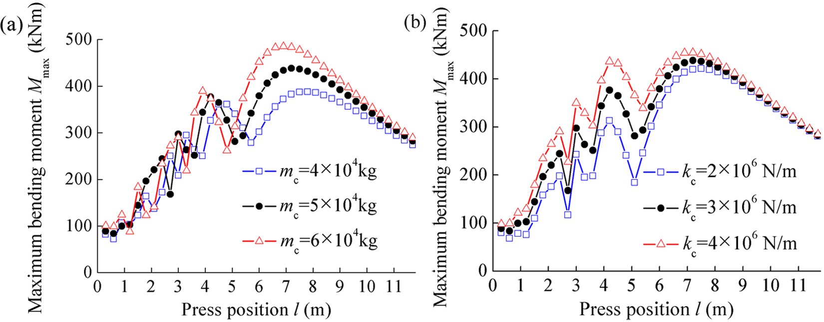
The effects of the manipulator parameters on the maximum bending moment Mmax. (a) Clamp mass mc; (b) compliance stiffness kc.
Influence of the clamp mass mc on the global maximum moment
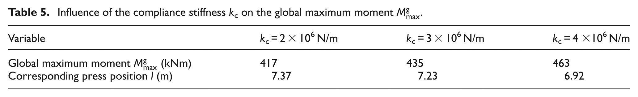
The effects of compliance stiffness kc on the maximum bending moment Mmax are plotted in Figure 18(b). The global maximums and the corresponding press positions for different compliance stiffnesses are listed in Table 5. The first term kc/k in equation (19) increases along with the compliance stiffness kc, which causes the increase of the maximum deflection ub,max as well as the maximum moment Mmax. So it can be seen from Figure 18 that the maximum bending moments become greater at all positions with the increase of the compliance stiffness kc.
Influence of the compliance stiffness kc on the global maximum moment
Conclusions
In a forging process, the bending moment transmitted to the manipulator owing to the press motion possibly causes damage to the workpiece. In this article, a SDOF model is proposed to analytically predict the bending moment, which yields more physical insight into the dynamic behaviour of the system. Theoretical explanations of phenomena are provided, which could not be achieve by numerical methods. Good agreements could be observed between the SDOF model and of the LS-DYNA simulation, both for the variation trends in the time domain and the maximum values (R2≥ 0.91, %SEP≤ 10). The results indicate that vibration induced by the press motion has a significant influence on the bending moment, including the value of the maximum moment and the corresponding time point for the maximum. The vibration behaviour of the manipulator system depends on the press position because the system stiffness changes with it. Furthermore, the influences of the manipulator parameters are studied, including the clamp mass and compliance stiffness.
The study of the theoretical results in previous sections indicates that the following conclusions may be drawn.
The maximum bending moment in time domain occurs after the press motion instead of during it.
The maximum bending moment first increases along with the press position, after reaching a peak value, it keeps decreasing. This trend is generated from a multiplication of an increasing function and a decreasing function. As a result, the global maximum in one forging pass occurs at the middle span of the workpiece instead of the two ends.
The bending moment imposed on the manipulator could be reduced by decreasing the clamp mass and the compliance stiffness.
Footnotes
Acknowledgements
The valuable suggestions from Professor Huajiang Ouyang (University of Liverpool, UK) are greatly appreciated.
Funding
This study is supported by the National Basic Research Program of China (No. 2006CB705403).