
Abstract
In industry, a precise two-dimensional, high-precision motion control system is in high demand. Compared with other types of two-dimensional direct-drive machines available, the planar-switched reluctance motor has the advantages of low-cost, simple structure and it can operate in wide temperature ranges. Considering the machine structure of the planar-switched reluctance motor prototype, mechanical improvements are performed and a compact planar-switched reluctance motor has been constructed with more mechanical robustness. Since dynamic response errors for the planar-switched reluctance motor-based position control system under a typical proportional–differential controller increases with the frequency of position reference, a dual-loop position controller cascaded to the proportional–differential regulator is proposed. Both simulation analysis and experimental results verify the position controller’s effectiveness of reduced dynamic errors with increased frequency and precise tracking of reciprocating motion command.
Introduction
A precise two-dimensional (2D), high-precision motion control system is in high demand in industry for many applications that require a repeated operation trajectory, such as electronic component insertion, integrated circuit packaging, central processing unit (CPU) manufacturing, etc. For direct-drive 2D actuators, instead of stacking two linear motors, the planar motor is a new candidate that can directly provide perpendicular X–Y translation forms with a moving platform remaining at the same height. 1 Current planar motors available are the Sawyer motor, the planar induction motor, the permanent magnet (PM) planar motor and the planar-switched reluctance motor (PSRM). The Sawyer motor2–4 has a lack of robustness and accuracy since its open-loop control nature often leads to a loss of steps and reduced precision. Although the motor can operate under a closed loop, the whole motion system is complex and the implementation cost is high.5–7 The planar induction motor8,9 has the disadvantage of complicated winding structures, therefore, the motor has high manufacturing costs and requires constant maintenance. Although it has a robust motor structure, the low output efficiency prevents its use for industrial applications. As for the PM planar motor, it either involves a complex coil structure or complicated magnet arrangement.10,11 Furthermore, the introduction of PMs inevitably raises manufacturing costs and prevents the machine from operation in wide temperature ranges. 12
The PSRM is mainly composed of laminated ferrite metal and windings with a simple and robust machine structure and it can operate under hostile environments with wide temperature ranges. Since no expensive or hard-to-handle materials are involved, the material cost for the machine is low. However, owing to the highly nonlinear characteristics inherent in the magnetic path, a proper linearization scheme should be introduced to achieve high-precision position control performance. In industrial applications, the proportional–integral–differential (PID), or its combination, is still a large dominance owing to its simple controller structure 13 and the motor often operates under reciprocating motion with a sinusoidal position command reference. The PSRM prototype has been built in our laboratory and a simple, yet effective, PD controller has been developed. 14 An approximately ±2% dynamic error to reference ratio can be reached. However, frequency characteristics are not taken into consideration and the machine exhibits as a high-pass filter from each axis of motion. Therefore, dynamic errors become larger with increased reference frequency.
In this article, after the mechanical improvements from the PSRM prototype, a compact, optimized PSRM is designed and constructed as discussed in ‘Mechanical improvements and machine construction’. Following the theoretical analysis of the proportional–differential (PD) position controller, ‘Derivation of the dual-loop position controller’ proposes a dual-loop PID controller for a reduced dynamic position error response with increased reference frequency. Simulation analysis is performed in ‘Simulation results’ followed by ‘Experimental verification’. Both simulation and experimental results prove the effectiveness of the proposed dual-loop position controller.
Mechanical improvements and machine construction
The PSRM can be treated as two identical 6/4 rotary SR motors “cut and extended” along both X and Y directions. Figure 1 shows the machine topology for any direction of motion.
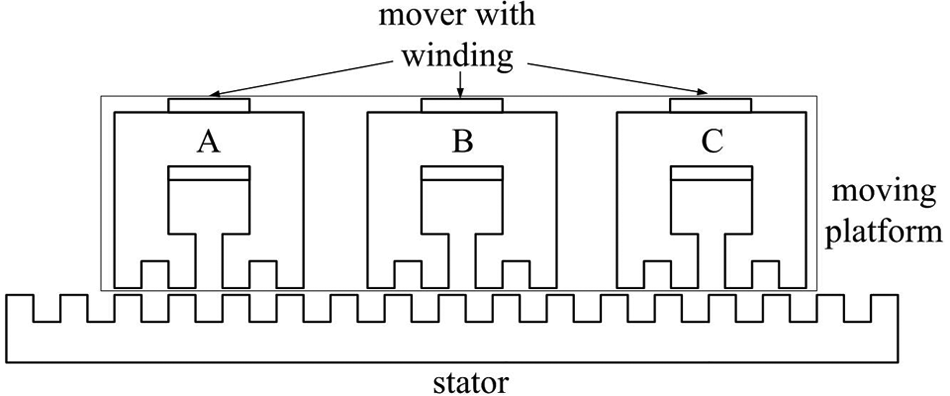
Machine topology for one axis of motion.
The planar motor is mainly composed of the following four components.
The moving platform with six movers and windings.
The stator base.
Two pairs of linear guides.
Two linear encoders for position information feedback from the X and Y axes.
The moving platform mainly consists of six movers and windings with three responsible for each direction as depicted in Figure 2. All movers and windings have the same dimensions and ratings. The design of phase windings for any axis of motion conforms to three-phase switched reluctance (SR) principles, that by the excitation sequence of phases A to C from the X or Y axis coils, the moving platform will translate along the X or Y direction, respectively.
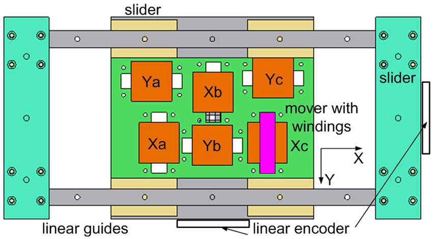
Structure of the moving platform.
To ensure magnetic paths in two axes perpendicularly and keep eddy currents at a minimum value, instead of carving the stator from a single slab, the LEGO stator block idea is employed and the whole stator is composed of a certain number of stator blocks to form any shape and dimension. As shown in Figure 3, the formation of the stator from a single silicon–steel lamination, a stator base of any size and shape can be constructed and the overall structure complexity and manufacturing cost can be significantly reduced.
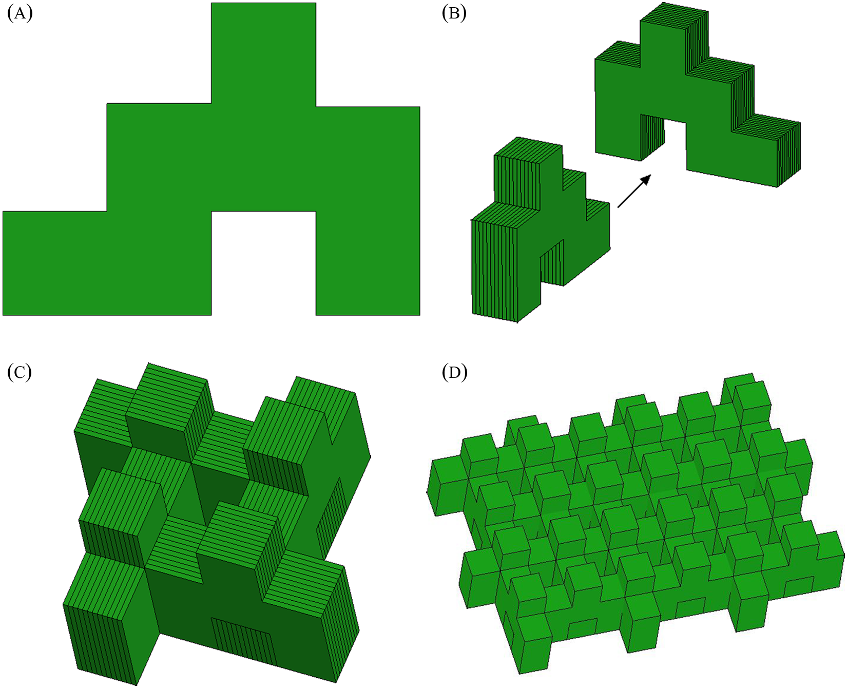
Formation of stator base from (a) lamination, (b) block, (c) stator element, and (d) stator matrix.
Except for the movers, stator blocks and linear guides with sliders, all mechanical supports or fixtures are made from aluminum alloy to reduce the overall weight and provide flux-decoupled magnetic paths.
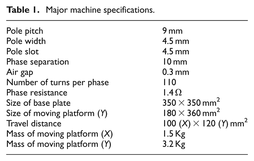
From the PSRM prototype proposed in Pan et al., 14 it can be found that the X-axis of movement is supported by a pair of bulky bar slides that impose a large mass to the whole moving platform. Since the X moving platform is fixed under the bar sliders with screws, there is a tendency of shape distortion when the coils are excited, which influences the effective air gap length between the moving platform and the stator base. To solve the above problem, an improved version of the PSRM has been built. As shown in Figure 4 of the mechanical structure of the machine, the same pair of flat linear guides are employed for both directions and for the X moving platform. The linear guides are suspended from the cover board of the moving platform and six movers are cut with protrusions so that they can be directly fixed onto the X moving platform with fasteners. All silicon–steel laminations are welded with a laser instead of holes with screws from the prototype. These mechanical improvements ensure a more compact machine structure and shorter magnetic circulation paths can be achieved. Two pairs of linear magnetic encoders are mounted for positional feedback for the two directions to replace linear optical encoders with the same resolution to lower system costs. Major specifications are tabulated in Table 1.
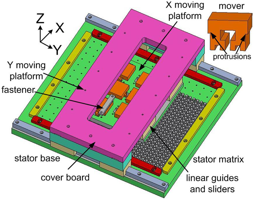
The compact PSRM.
Major machine specifications.
Derivation of the dual-loop position controller
The PSRM model
Regardless of disturbance, the open loop transfer function of the PSRM for one axis can be approximately represented as a typical second-order differential equation as 15
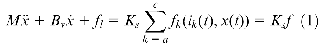
where
From the electrical side, the relationship for any one phase from the X- or Y-axis of movement can be characterized as voltage balance equations
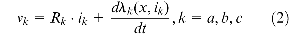
where

where
Linearization scheme
Since single-phase excitation for the SR machines inevitably produces force ripples,
15
a multi-phase excitation scheme is applied for the smooth operation of the PSRM. The phase excitation method, tabulated in Table 2, depicts the excited phase(s) and force reference values according to current position
The multi-phase excitation scheme.
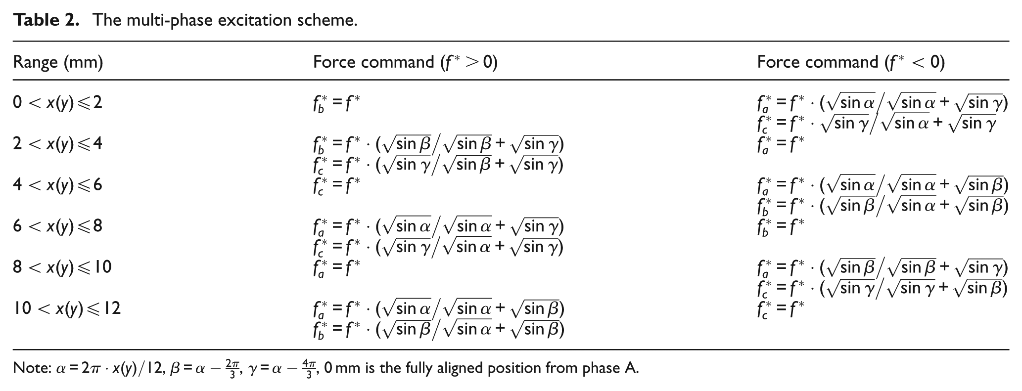
Note:
To derive the current reference from the position and force command of each phase, a simple yet effective 2D look-up table, based on bi-linear interpolation, 14 is applied. The inverse relationship between the force command, position and current is measured through experiment and a pair of force command–position–current look-up tables for each axis is constructed. Experimental verification between the force output for one single-phase and the force command can be found in Figure 5. It can be seen that force output profiles exhibit a linear relationship with moderate variations according to the force command at different positions. Therefore, the multi-phase excitation with 2D look-up tables is suitable for linearization of the PSRM.
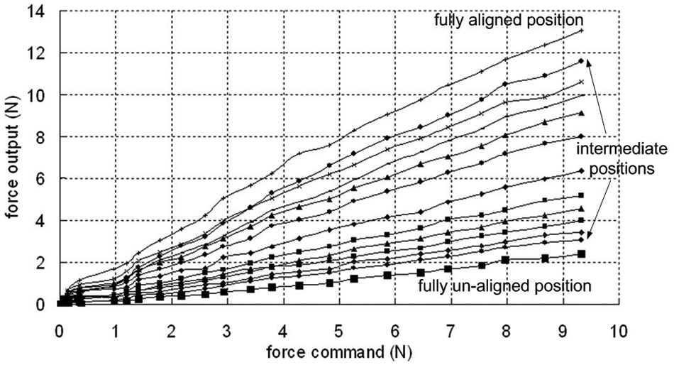
Relationship between force command and output at different positions.
The position control diagram can be derived as shown in Figure 6. According to the current position and control output from the position controller, the linearization scheme first decides which phase(s) should be excited and the force command
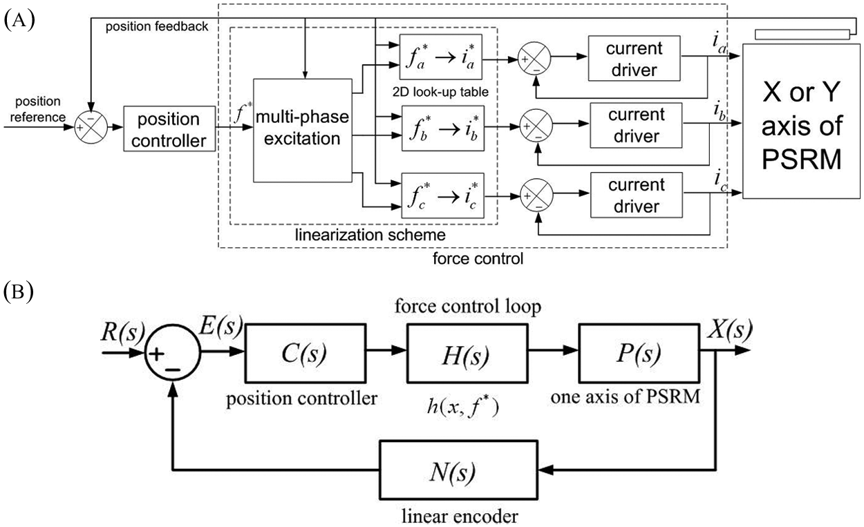
(a) Force control loop in the position control diagram with multi-phase excitation and (b) position control diagram.
Regardless of load, the open loop transfer function for any axis of motion of the PSRM can thus be expressed as

The PD position controller
The PD position controller takes the form

where
The dual-loop PID controller
The error transfer function for the PD-based control system can be derived as
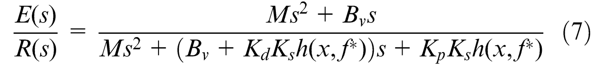
For practical gain tuning, the proportional gain
To transform the error transfer function into a low-pass filter and decrease steady state error to zero in the low-frequency band, an inner proportional loop with feedback is proposed and cascaded to the PD position controller as illustrated in Figure 7.
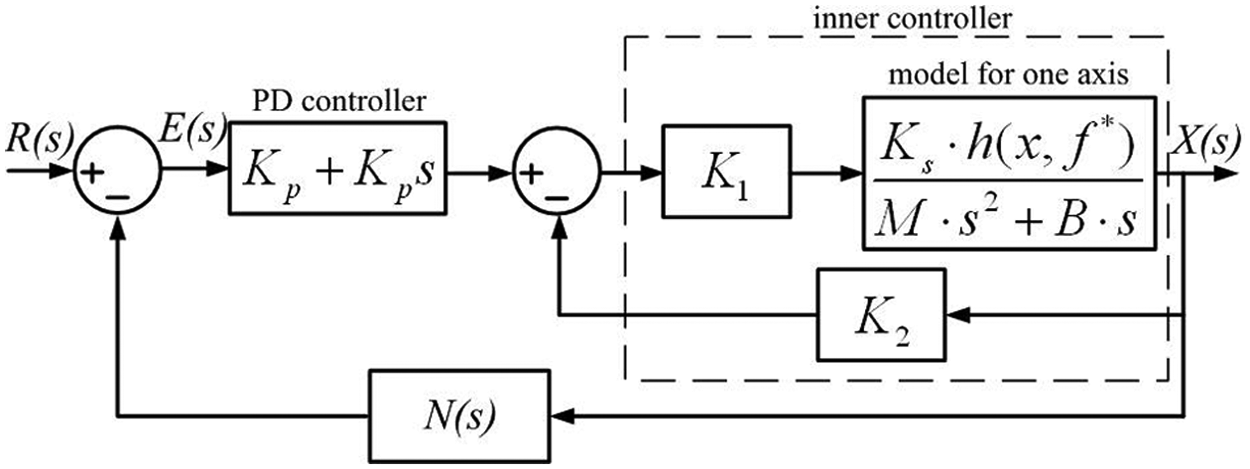
Structure of the dual-loop position controller.
Where
respectively with

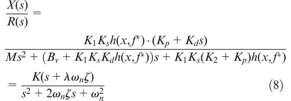
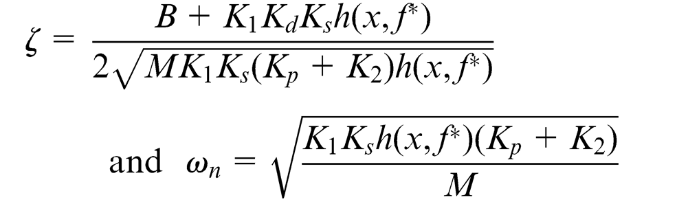
Then the poles for the closed loop transfer function can be found as

Since the variables or constants in the equation are all positive, the real part of the poles can be negative if
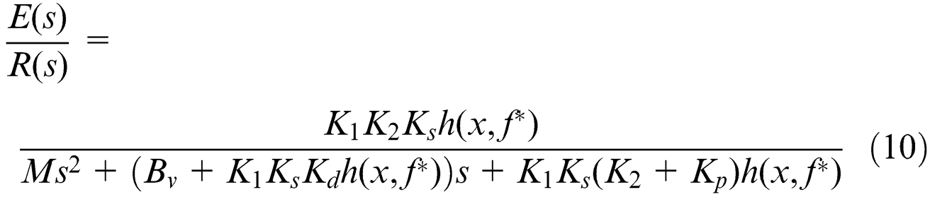
The dynamic response errors approach zero as long as the difference between the order of the numerator and denominator is less than two from the transfer function of the input signals, so the model belongs to the II-type (second-order error free) system. 17 As can be deducted from the above equation, dynamic response errors decrease when the frequency of the input signal increases.
Simulation results
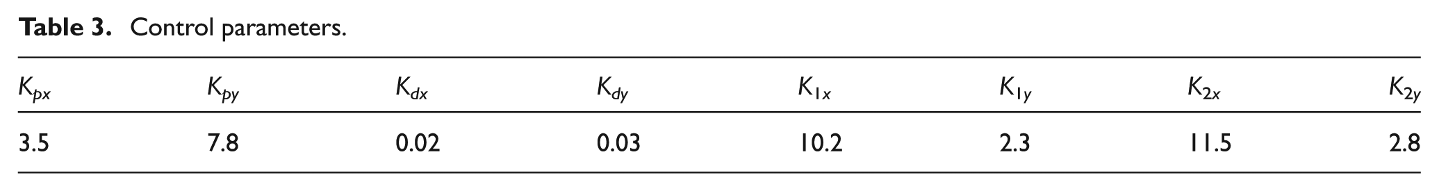
Simulation analysis is carried out under a MATLAB/Simulink environment. By properly choosing appropriate gain values, the control system is stable with a static precision of 10 µm. 14 The gain parameters are selected according to the second-order dynamic response of the system for a reciprocating sinusoidal position reference. 17 They are further fine tuned by repeated trial and error following the control parameters listed in Table 3.
Control parameters.
Simulation for the PD position controller with a sinusoidal input signal by increasing the input frequency from 0 to 5 Hz is performed for X-axis of motion. From the simulation results illustrated in Figure 8(a), at low-frequency range, the dynamic response error values become larger as the reference frequency increases. For the case of the dual-loop controller, however, as the frequency increases, the dynamic response error values tend to decrease. Therefore, the control system behaves as a low-pass filter.

Simulation of dynamic error response of the X-axis for (a) PD position controller, and (b) dual-loop position controller.
Experimental verification
The experiment is carried out based on a peripheral component interconnect (PCI)-based dSPACE DS1104 controller card. The controller card interfaces with the MATLAB/Simulink program in real time and the parameters from the program can be regulated online. As shown in Figure 9 of the overall experimental setup, the host personal computer (PC) is a Pentium 4 computer for target code download to the controller board digital signal processor. There are altogether six current drivers with asymmetric bridge insulated gate bipolar transistor (IGBT) inverters for the current supply of six phases from the two axes. The commercial amplifiers are capable of inner current regulation based on a proportional–integral (PI) algorithm and are fast enough to meet the requirements for the position control loop with 20 kHz switching frequency. The sampling frequency for the position control loop is chosen as 1 kHz. Two linear magnetic encoders with resolution of 1 µm are mounted on the moving platform for real-time position information observation for each axis of motion.
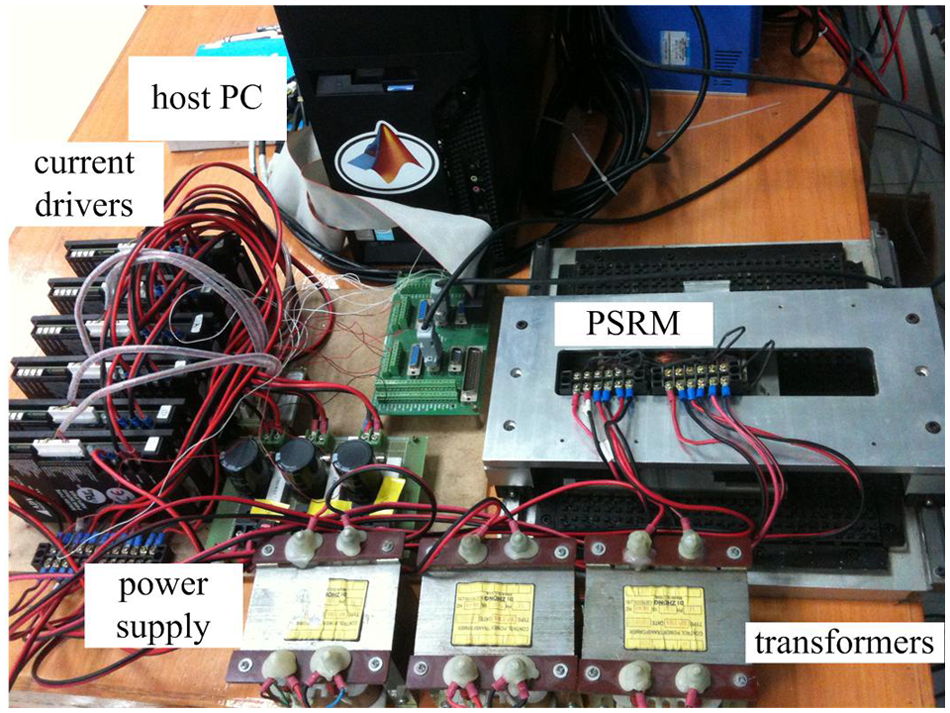
Experimental setup.
Owing to its mechanical limitations and electrical constraints, the PSRM is designed to operate within a reference frequency of 2 Hz with a peak-to-peak range of ± 30 mm. The corresponding experimental results of dynamic error response, based on PD position controller for both axes, are illustrated in Figure 10(a) and (b). As shown in the diagrams, dynamic errors increase prominently as the frequency gets larger for both axes. Owing to asymmetry from mechanical manufacture, errors from positive and negative cycles are not uniform for each axis. The case is even worse for the Y-axis since it carries the entire weight of the X-axis with larger mass and inertia. From the experimental results, the error–input transfer function for each axis of motion behaves as a high-pass filter that validates the theoretical analysis and simulation results.

Dynamic error response from PD controller for (a) X-axis, and (b) Y-axis of the PSRM.
After the dual-loop position controller is cascaded, the error response for the X- and Y-axis can be found in Figure 11(a) and (b), respectively. As the reference frequency increases, the error values tend to diminish. Therefore, the dual-loop position controller is proved to be effective. Since the Y moving platform carries more weight and translates together with the X one, it encounters more variations and disturbances and the dynamic error values are even bigger at specific operating frequencies.

Dynamic error response from PD controller for (a) X-axis, and (b) Y-axis of the PSRM.
Since each axis of motion is decoupled from one another 15 with “sin” and “cos” signals with the same phase, cycle and amplitude selected as the tracking command for each axis of motion, the motor will draw a circle under the composite command. Error dynamics for each axis and the overall response can be found in Figure 12. It is clear that the dynamic error response from opposite directions of motion is not identical. This is because the mechanical structures are not uniform and each moving platform experiences unbalanced frictions at distinct positions. However, the experimental results prove that the control system based on the dual-loop position controller is capable of following the command signal precisely with a maximum 1.3% of dynamic error response.
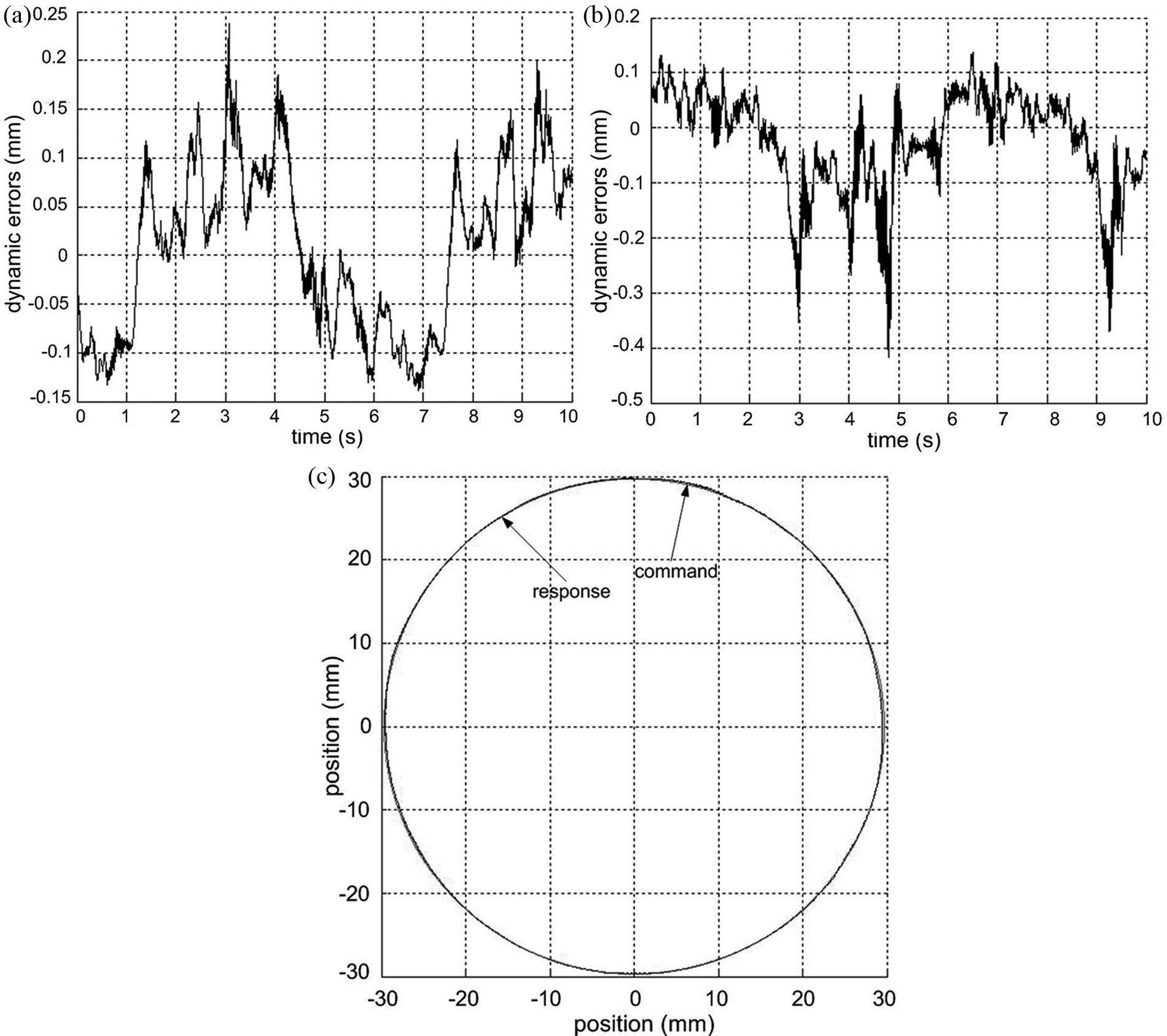
Dynamic error response from dual-loop controller (a) X-axis, and (b) Y-axis and (c) overall performance.
Conclusion
In this article, mechanical improvements for the machine structure have been made according to the PSRM prototype and a compact PSRM with more mechanical stability and robustness is constructed. Since the typical PD controller for the PSRM behaves as a high-pass filter and dynamic errors become larger as the reference frequency increases, a cascaded dual-loop position controller is derived and cascaded to the PD controller. Both simulation and experimental results prove its effectiveness of decreased error values under increased frequency. Since the control algorithms are derived from linear equations neglecting disturbances, such as parameter changes or external variations, a uniform performance of the PSRM for each axis is hard to be achieved based on PID algorithms. For practical use of the machine to operate repetitively, it is suggested that an intelligent control method, based on iterative learning control (ILC), be implemented to obtain a desired transient response under unmodeled dynamics or parametric uncertainties. 18 A more perfect tracking performance is expected to be achieved under such robust controllers for trajectory regulation of the PSRM to adapt to the working environment for industrial applications.
Footnotes
Funding
The authors would like to thank the National Natural Science Foundation of China and Guangdong Natural Science Foundation for sponsoring of research projects under the project code 51007059 and S2011010001208; the authors would also like to thank Shenzhen government fund JC201005280390A and ZYB200907080073A for support.