
Abstract
Real time visibility of product-centric data has become increasingly important to original equipment manufacturers in order to optimise supply chain operations, increase quality, reduce resource usage and increase the retained value at the end-of-life of the product. The development of a system capable of supporting collection and visualisation of product-centric data that is used in life-cycle monitoring systems for electronic products is described in this article. The concepts behind intelligent products in the electronics manufacturing domain are discussed. In particular the research is focused on which product-related information is needed throughout the supply chain and how business processes can be optimised if this knowledge is available. A review of intelligent products is outlined and product information that is generated and travels with the product through the supply chain is described by analysis of business processes and identification of those processes, which could be made redundant if product-related data were available. A survey of manufacturing experts within this domain has been undertaken to determine what information should travel with the product, what opportunities exist for embedded information and what barriers for the implementation exist with regard to the specific constraints and needs in the electronics manufacturing domain. The results of this survey are discussed with conclusions drawn and future research derived and described.
Keywords
Introduction
Real-time collection, visualisation and knowledge extraction of product-centric data has become increasingly vital for original equipment manufacturers (OEM) to control the production, in corporation with multiple suppliers, global distribution, servicing and the collection and disposal or recycling of its products. The need for visualisation of product-centric data (PCD), which is used in life-cycle monitoring systems for electronic products, is described in this article.
Globalised competition and customer expectation demand high variety, high quality products for low costs and force OEM to optimise manufacturing and supply chain operations. Agile manufacturing concepts, the capability of a company to react quickly to changing customer demand, has become an essential requirement to meet demands for high variety. A key characteristic for agility is flexibility. 1 Agility is not only restricted to manufacturing operations, but also includes its related information systems to monitor and control manufacturing as well as business operations. Detailed product information, such as location in the supply chain, visibility in manufacturing, production process steps and results need to be available to synchronise agile business operations and manufacturing systems, e.g. order management, production scheduling or after sales services.
Agility is not only required from OEM operations. The production and services around products involve globalised and diverse supply chains. These supply chains also need to be organised with focus on agility to enable OEM to control the product flow, part manufacturing and quality control in an agile manner. The OEM need to have a high supply chain visibility and production process visibility over the whole supply chain.
This article discusses the concept of intelligent products in the electronic product domain. In particular, it researches which product related information is needed throughout the supply chain and how business processes can be optimised, if this knowledge is available. In ‘Literature review’ a review on intelligent products is outlined. ‘Usage of PCD’ describes the product information that is generated and travels with the product through the supply chain. In ‘RFID in the life-cycle of electronic products’, business processes are analysed and processes identified that could be made redundant if product related data were available. An expert survey is undertaken to answer the questions of what information should travel with the product, what opportunities exist for embedded information and what barriers for the implementation exist with regard to the specific constraints and needs in the electronic manufacturing domain. The derivation of technical requirements and system design is not covered in this article. The authors show in Bindel et al. 2 how intelligence can be embedded into an electronic product, by means of embedding a bare radio frequency identification (RFID) chip into the structure of the printed circuit board (PCB), and how a system can be designed.
Literature review
Definition of an intelligent product
The term intelligent product or active product has been used in academic publications for a while to describe a product that does not only behave as an object, but also has embedded intelligence. To describe a product as intelligent provokes different thoughts of what the product is actually capable of doing. Various authors have given a definition for an intelligent product to avoid this ambiguity.3,4,5 Although these definitions vary from each other, there are key common elements that define an intelligent product. These general elements are shown in Figure 1.
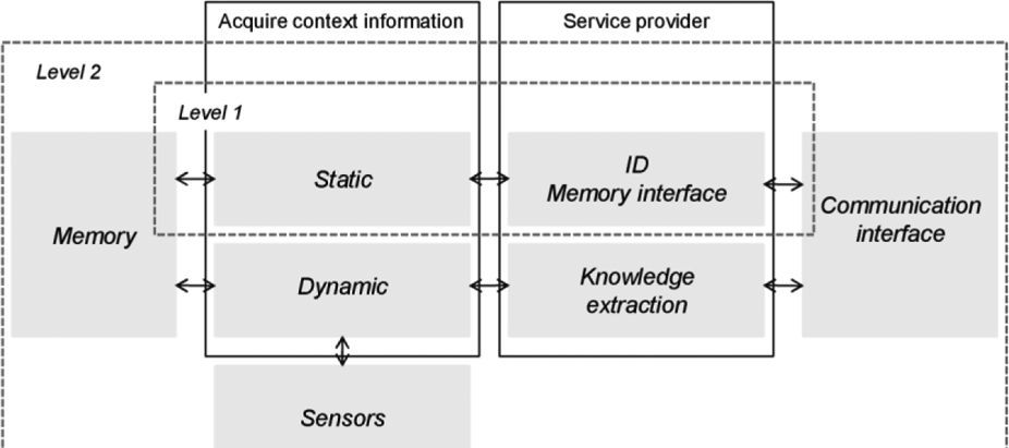
Key elements of an intelligent product.
The intelligent product must have a memory to store context information, which could be static or dynamic data as classfied in Scheidt and Zong, 6 with static data being data relating to specifications and configurations, and dynamic data being data that occurs during distribution, usage and end-of-life. Static data can be written to the memory via the communication interface (e.g. process steps, material contents). Dynamic data is usally acquired by sensors.
Second, an intelligent product should have implemented a service provider that offers services via a communication interface to the outside world. The services could be as simple as providing the unique ID of the product or an interface to the internal memory. If the product has implemented computing mechanisms (e.g. software agents) it could extract knowledge from the acquired data and offer this as a service.
The different levels of the intelligent product, as defined in Wong et al., 3 can be generalised as follows.
Level 1 (information oriented): a product capable of storing static information and providing unique product ID, and access to the memory via a communication interface.
Level 2 (decision oriented): a product with level 1 capabilities and ability to read dynamic data via sensors, and is able to extract and provide knowledge from the acquired data.
A unique identification of the product can be provided by these automatic identification technologies (e.g. barcode, two-dimensional matrix, RFID) as it is shown in Figure 2. For example, the RFID tag can provide a unique number (e.g. an electronic product code) that can uniquely link the physical product with a digital representation. 7
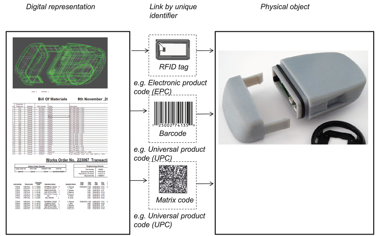
AutoID tags link digital representation and physical product via unique identification.
The digital representation of the physical product establishes the possibility to augment the physical product with additional information (e.g. lifetime information, bill of materials, special instructions) or digital interactions (e.g. data aggregation and interpretation, interaction with control systems). Baïne et al. 8 discusses this separation of the physical and digital product by dividing the product into an actual, tangible product and the augmented product as the non-physical part. Both of these together would form the core product, which is defined as the benefit of the product that makes it valuable to the customer. Consequently, the value of the product can be increased by adding additional services that can be derived from the product’s context (e.g. location, usage or usage history).
The digital representation does not necessarily need to be embedded into the product itself. This leads to another dimension of the characterisation of intelligence: The location of intelligence. 9
The location of intelligence can be established remotely (e.g. in database systems) (intelligence through network) or embedded into the product (intelligence at object). The service provider can either handle information only, previously classified as level 1. With higher intelligence, the service provider can notify events (problem notification) or make decisions on its own. This higher level corresponds to a level 2 or decision-oriented intelligent product. Meyer distinguishes the aggregation level of intelligence as intelligent item, an item that is only aware of its own, and an intelligent container, defined as a product or component that is also aware of surrounding components or products.
Usage of PCD during a product’s life cycle
As defined in the previous section, an intelligent product has to be able to acquire context information that relates to the product, its environment and products it has a relation with. Product information from previous stages is also used for decision making in different life-cycle stages. Context information, which is acquired related to the product, is divided and described in literature in different areas during the product’s life cycle, i.e. design of the product, manufacturing/distribution, usage/service, use phase and end of life.
Usage of AutoID systems
To comply with the European Directive on waste electrical and electronic equipment, producers have to provide customers of electronic products with disassembly and recycling information. This information is created in the design stage and must be available at the end of life. Stutz et al. 10 describes how barcode technology can be used to link this recycling information to a specific product.
It has been explored how the tagging of material parts can increase the efficiency of production systems by real-time locating of these parts. Thiesse and Fleissch 11 showed that location systems can significantly increase machine utilisation and manufacturing throughput. 12 Information, which mainly is available at the production control system, e.g test results, operator name and process ID, can be visualised and made available in the enterprise resource systems (ERP) and can support production management decisions. 13 Information about failures reworked on a specific product can be used to fast trace back malicious products when a failure occurs in the field. The main difference between RFID systems in production and supply chain application is the usage of different types of tags. Production and manufacturing RFID systems are mostly closed-loop applications. This means that the tags stay in the company and are reused. Supply chain management and logistic applications use open loop systems with none-reusable RFID tags. However, only limited information can be accessed during the whole life cycle if closed loop systems are used. In electronics manufacturing, only part of the supply chain can benefit from opportunities of an identification technology, if the RFID tag is attached during electronics manufacturing.
The first and most famous application of RFID technology, however, is in the retail market. Added tags to products are used to reduce inventory stocks and therein the costs of out-of stock items. 14 Key players in the retail sector that have implemented AutoID systems are Wal-Mart, METRO and Target Corporation. In the case of perishable goods, researchers work on ways the delivery time can be reduced with the help of RFID. Research results propose dynamically allocating perishable products from food processing packaging companies to distributors, and then from distributors to retailers, which will lead to a reduction of lost products. 15 But, the absence of co-operation between corporations is an obstacle when implementing RFID-systems in food supply chains. To gain full revenue of the system, various companies of the supply chain have to implement a linked or shared RFID system. It has been shown that the overall supply chain cost can be reduced by 5–10%. The retailers and other users of RFID technology, until now, have focused on the life time until the product is sold. Still, there are wide possibilities for increasing cost efficiency when making the product visible after selling. Current research here is done, for example, by Niazi et al. 16 The researchers focus on the middle-of-life (MOL) and end-of-life (EOL) monitoring of goods. They propose to use the RFID tag to identify sensors on products with its unique identification. The goal is to get feedback from the MOL and EOL to the beginning-of-life of products.
At the EOL, product specific information is normally no more visible to the recycler, as links to manufacturer’s databases are normally not available. However, legislation, for example the WEEE directive, now forces the producer to take back used electronic products. Research proposes to optimise the management of multi-life-cycle management by RFID tags. 17 The Austrian Society for Systems Engineering and Automation in Vienna established a multi-life-cycle centre. Here they try to control product streams of electronic goods with the help of RFID tags. 15 The University of Cambridge organises an AutoID lab, where they analyse, how an RFID electronic product code (EPC) can be used to manage information in the product life cycle. 18 With the help of RFID they propose an intelligent product that has information content permanently on the product itself. They investigate how such an intelligent product can be used to enhance life-cycle management.
Intelligent products and their usage are defined and described for different applications. These applications are mostly based on identifying and locating products. However, no definition of what information and services have to be stored in a product for a specific domain or what specific opportunities arise from that. In particular, it is not defined what information and services should be embedded into an electronic product.
Embedding components into the PCB
Different research and development approaches have been undertaken to embed components into a PCB, such that components cannot only be placed on either side of the PCB, but also between the layers of the PCB. Not only miniaturisation, but also signal integrity (e.g. decoupling power supply) improvements, are the drivers for the embedding of components within the PCB. The components can either be embedded into the dielectric layer with micro-via connections to the conductive layer, or by using flip–chip assembly techniques to connect the chip on the copper layer, such that the chip is embedded within the pre-preg material as shown in Figure 3.
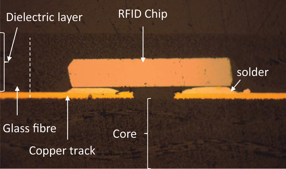
Embedded RFID into the dielectric layer of a multilayer PCB.
Two major European projects have been funded by the European Union to research the technology to embed active components into the dielectric layer of a PCB. The Framework Program 6 (FP6) funded project HIDING DIES (12/2003–12/2006) and FP7 project HERMES (5/2008–5/2011) focus on the technology in which the component is placed ‘face-up’ on the core board and micro-via connect to the chip connections. The usage of flip–chip technology for embedded RFID components into the PCB is described by Bindel et. al. 2 The embedded RFID offers the possibility to uniquely identify PCBs from the beginning of manufacturing and to store additional information into the memory of the RFID.
Usage of PCD
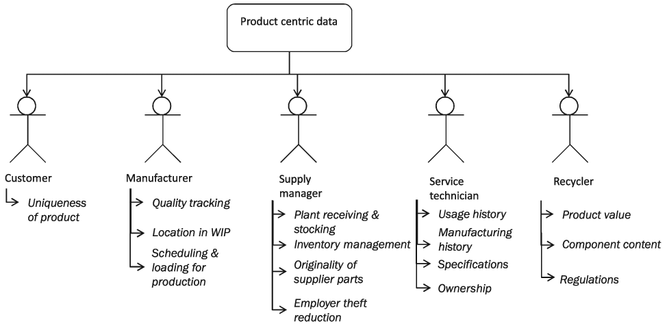
Although identification techniques such as barcode and RFID exist, a real-time view on products exist normally within company constraints for company-specific purposes, such as inventory management, automatic billing systems or asset tracking. However, this is often realised on a batch level and for every single product. A visualisation of the PCD throughout the whole life time of the product is not commonly available. Different stakeholders, as shown in Figure 4, i.e. customers, manufacturers, service technicians and supply chain managers and recyclers, have to have a visualisation of all relevant data at the right time in the right format, e.g. work-in-progress status, inventory level, process history of products, location, use profile, material and component content of a product. 18
Use of PCD for different stakeholders.
The different people need different information during the product’s life cycle and can benefit in different ways if PCD is available (see Figure 4). The customer can judge, if the product is unique. The manufacturer needs to have all information for quality tracking and control (tracing of errors, root cause analysis), locate products in WIP or scheduling and loading of production. The supply manager needs product related information to manage the plant goods inwards and component stocking to optimise inventory, check supplier parts on originality and control product movement, e.g. for employer theft reduction. The service technician requires information related to usage and manufacturing history of the product to optimise pre-emptive schedule services or reduce servicing time. They have to have access to specifications and the ownership of the product. The recycler uses the product value and component content information to increase the recycling value of the product. They also have to be aware of regulations or special instructions regarding the product.
Constraint 1
Different stakeholders need different information. The information related to the product, article-based or digital, is passed on and visualised independent of the viewers role. Non-individualised visualisation increases the time to find relevant data and can cause error by selecting the wrong information. ▪
Information flow of PCD in the supply chain
The supply chain of a product is shown in Figure 5. It provides an example of a supply chain for an electronic product. The PCB manufacturer, electronics manufacturer and OEM comprise the main stages in manufacturing the product. The main material flow passes through these three stages. Additionally, material and components are purchased and used during these stages. Relevant product-specific information, which is directly linked to the product itself, is held in databases for the use in manufacturing execution systems (MES), production planning systems (PPS) or ERP. This creates a flow of the physical and the digital product. For supply chain integration it is essential that these two flows are synchronised throughout the life cycle of the product. 8
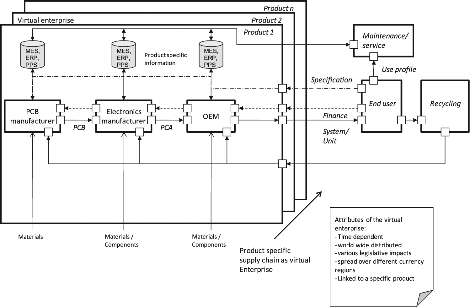
Supply chain of a specific product described as a virtual enterprise.
Constraint 2
The flow of the physical and digital product is mostly different. The physical product is shipped from one supply chain stage to the next. The digital information is often fragmented as part of the information is kept in one supply-chain stage and part of the information is passed on to the next supply-chain partner or the end customer. ▪
The specification of the final product is defined by the end user and is broken down in sub specifications for the PCB manufacturer, electronics manufacturer and OEM. The supply chain stages may vary for each specific business opportunity and can be as small as a single product or within the series of specific products. The information related to the product, though, stays generally invariant. For example, the electronics manufacturer could change, while the rest of the supply could stay the same between different products.
Constraint 3
IT integration through the supply chain does exist, but the implementation time often takes longer than the product and the supply chain life time. This makes it unfeasible to implement specialised IT systems as they are not flexible enough. ▪
The supply chain, which is involved in manufacturing of a specific product, can be seen as a virtual enterprise as described in Barnett. 19 It could be observed that international competition has migrated from competing companies to competition of supply chains. As a result, close integration of business processes across the members of the supply chain has become necessary. 20 This virtual enterprise, a concept described in literature as a ‘temporary collaborative network of independent enterprises, formed to exploit a particular business opportunity’, 21 is time dependent, worldwide distributed, influenced by various legislative systems and currencies and can be limited to one product. Although literature describes how to model and optimise virtual enterprises as a managing activity, it can be argued, that any business that involves a supply chain fulfils the criteria of a virtual enterprise to meet customer and legislative demands.
Although the supply chain of a product can be seen as a virtual enterprise, the information flow between the supply chain partners, which is necessary to achieve agility and interoperability, is hindered by the information barrier, which practically exists between the partners owing to IT restrictions and system variations at the company borders.21,22 Figure 6 shows an example of this barrier in the electronics manufacturing supply chain. The electronics manufacturer only passes the Gerber files, solder finish and materials to the PCB manufacturer. The PCB manufacturer then dispatches only the PCB, together with the dispatch info, and the final test results. PCB manufacturing data, such as the manufacturing processes, operator names and process test results stay confined to the PCB manufacturers MES, PPS and ERP system.
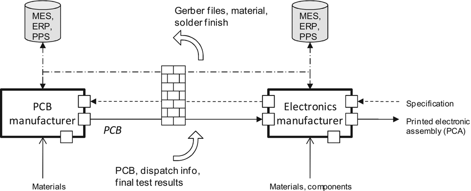
Information barrier between supply chain partners.
Constraint 4
Full information is not available at all times. Lack of information at a specific point will cause decisions to be made according to experience or standard procedures, but that are not optimised for the specific product, e.g. during quality assessments, maintenance or at the end-of-life of the product. ▪
Classification of product specific information
The information that is gathered through the life time of a product can be divided into two different types, static and dynamic information.4,23 Figure 7 shows the product specific information structure. The static information consists of the structured and deterministic data of the product, i.e. manufacturing process history including the processes with the related test results and the operator.
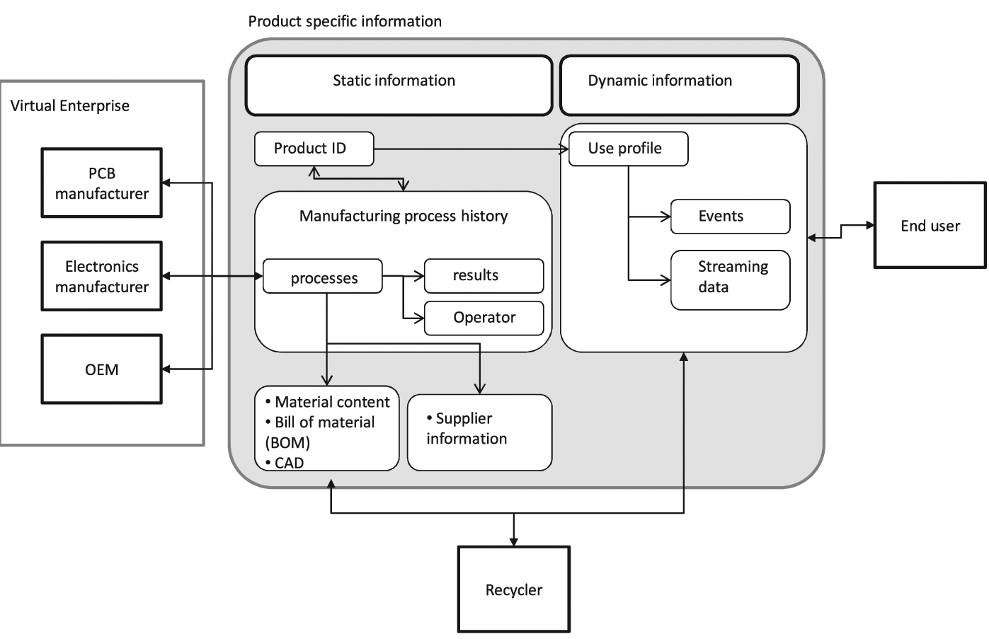
Information structure from the perspective of a product.
This process history is updated by all value adding partners in the supply chain, e.g. PCB manufacturer, electronics manufacturer, OEM in the electronics manufacturing supply chain. Additionally, it contains the static information, the unique product ID, material contents, bill of materials (BOM) and design information such as computer-aided design (CAD). The dynamic information contains the information parts that are not known during the design or manufacturing stages, and do not occur deterministically, such as handling forces and accelerations, or excess temperature exposure of the product. This type of information is denoted ‘use profile’ in Figure 7 and occurs either as events or, when sensor signals are monitored, as streaming data. This information can be used in a recall to decide if the product was used out of its specification, or at the recycling stage, to determine whether specific subassemblies or components can be reused.
Dynamic data, which is acquired with sensors, can be written directly into the memory of an RFID in real time. However, this requires that the RFID has an external interface to the memory. This is, for example, the case for the Ramtron RFID chip with serial peripheral interface (SPI).
RFID in the life cycle of electronic products
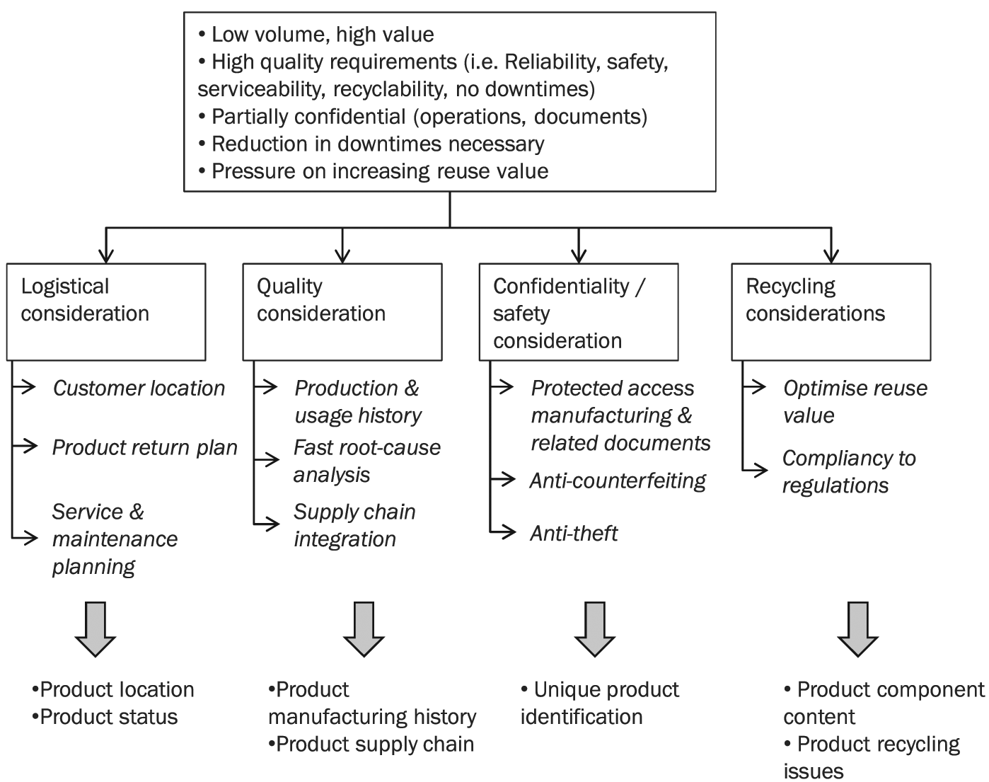
Manufacturers of electronics products face specific challenges and needs concerning product related information, as shown in Figure 8. In particular UK and European manufacturers produce majorly low-volume, high-value products with high quality requirements, i.e. on reliability, safety, serviceability, recyclability and no downtimes during operations. The major markets, such as aerospace, automotive and military, demand these requirements as well as commercial and military confidentiality of parts, operations and related document. New product sales models, such as product service systems (PSS), are used when companies sell a product as a service rather than a product and charge per hour of operation of the product rather than selling the ownership of it. These concepts request shorter time from order to service, reduced downtimes during use phase, increased lifetime, and increased reuse value to be profitable.
Considerations for low-volume, high-value electronic products.
These specific needs in the electronics manufacturing domain constitute logistical, quality, confidentiality and recycling consideration. Distribution and product return plans need to be optimised and service and maintenance planning needs to be scheduled – preferably pre-emptively – to reduce downtimes. Essential product information on location and status needs to be known to meet the logistical considerations. Quality considerations and regulations on quality require storing production and usage history; a fast root-cause analysis needs to be carried out in a case of malfunctioning. The supply chain needs to be integrated to create a reliable information flow for high quality manufacturing. This requires knowing the product manufacturing history and visibility of the supply chain. Confidentiality and safety issues force products and related documents to be kept protected, theft needs to be circumvented and products need to be protected from counterfeiting. This means that products have to be uniquely identified at all times. Optimal value and compliancy to regulations (e.g. the WEEE directive) can only be realised if the product components content and specific product recycling issues are known.
The information flow and physical product flow is shown in Figure 9 for the electronics manufacturing supply chain. Static information, such as CAD, BOM, gerber files, drill files, stack-up, net lists and documentation, is usually passed from OEM to electronic assembly and to the PCB manufacturer in digital form using email or file transfer programs. Different file formats and information are needed by the PCB manufacturer and at the electronic assembly. Attempts have been made to find a unified database/file structure for the product related information, such as odb++. However, information is passed on individually and has to be integrated into company internal IT systems. Some of the production and product related information is passed on between the different stages, such as final test results or baking requirements. This, however, is normally done together with the dispatch note in a non-standardised way. This could be either in paper-based form or electronically. However, most of the manufacturing information related to a specific product is kept within the company boundaries. Different supply chain partners need to be consulted in case of malfunctioning of a product. Viable information for root-cause analysis is not available with the product, e.g. process list, process results, operator names, process times, material usage, process environment (e.g. bonding and temperature profiles).
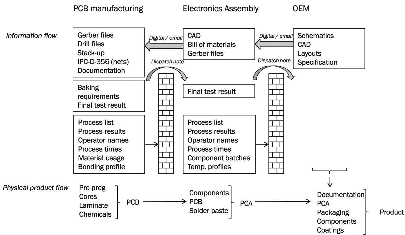
Information flow and physical product flow in the electronics manufacturing domain.
RFID tags embedded within the structure of a PCB offer a huge opportunity for the electronics manufacturing supply chain, in that product-related information can be stored with the product and embedded functionality can lead to increased visibility of product-specific information, which can be gathered and presented specifically for different stakeholders throughout the product lifetime. Ideally, the RFID tag is located between the internal pre-preg layers, as described in Bindel et al. 2 Life-cycle relevant static and dynamic information, as defined in the previous sections, can be stored within the product. This data can be passed on with the product from PCB manufacturing to electronics manufacturing, to the OEM and end user, and finally to the recycler. Information that is generated throughout the different stages of the life cycle is stored in specified sections in the memory of the embedded RFID.
Needs, opportunities and barriers for embedded RFID during manufacturing
A survey for the manufacturing of electronics products was designed and has been undertaken to determine specific needs, opportunities and possible barriers for embedding RFID tags into printed circuit boards. The survey was distributed among manufacturing engineers in electronics manufacturing companies. Experts working for contract electronics manufacturers (CEM) and OEMs were included in the survey. The companies represent the high-value, low-volume electronics manufacturing market, such as for aerospace and military applications. In total, 10 experts responded to the survey. As the responding experts have wide experience in the market and in manufacturing practices in particular, this survey can be seen as sufficiently representative for the UK high-value, low-volume market.
Information flow through the electronics manufacturing supply chain
The material and information flow through the supply chain stages during the production of an electronic product is shown in the process diagram in Figure 10. Main internal and external processes are illustrated. The flow of information, which originates from the OEM as a request for quotation, is shown as a solid double line with arrow heads. This information is first passed to the electronics manufacturer’s domain process (DM) 1 ‘commercial product realisation’. The request is acknowledged and the output of DM1 is a job pack, which includes the process steps in the form of the route card, special customer instructions and BOM is sent to ‘DM2 product manufacturing’. Manufacturing data for the PCB and the BOM is also sent to the supply chain operation (DM5), where materials, components and the PCB from the PCB manufacturer are ordered. The PCB manufacturer creates a job pack in ‘DM1 commercial product realisation’ and initiates manufacturing upon receipt of a ‘request for quotation’ and relevant manufacturing data from the electronics manufacturer.
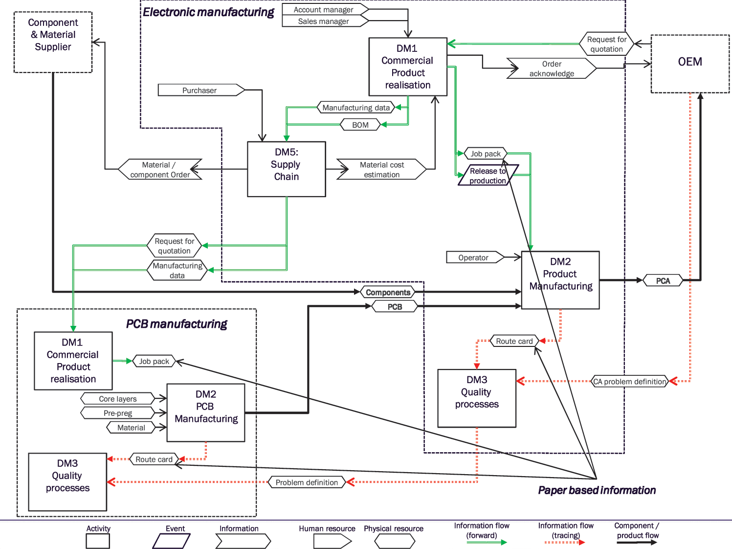
Information and material flow in the electronics manufacturing supply chain.
In contrast to this core information flow, there is also additional information required about manufacturing operations if corrective actions (CAs) are requested by the OEM or quality data are needed to be evaluated. This kind of information is shown in Figure 10 as dashed double arrows. CAs problem definitions are sent from the OEM to the electronics manufacturer. All information, which is needed to perform root-cause analysis and other customer concessions, are gathered in the domain process ‘DM3 quality processes’. The information is currently extracted from the route card, where the manufacturing processes and quality data are stored. Further manufacturing data are also requested from the PCB manufacturer in the form of a problem definition. The finished physical PCB and the components are sent to the electronics manufacturer and then the finished printed circuit assembly (PCA) to the OEM. It can be seen that the physical component or product flow follows different paths than that of the information, although the information is uniquely linked to the physical product.
Data collection of process information
Static information, i.e. structured data associated with product configuration, and manufacturing data is collected during manufacturing by each company so that it can be used in further quality and traceability processes. Dynamic data however, i.e. unstructured data such as temperature profiles or mechanical shocks, is normally not stored in relationship to specific boards in current practise. Some companies store information manually, i.e. paper-based route cards containing operator ID and process results after each process step during manufacturing. Other companies store this information electronically and record it after each step, or they store information only after selected process steps.
Information required throughout the electronics manufacturing process life cycle
In the survey, process experts were asked which information relating to PCB manufacturing is important to them. The information that is frequently required by manufacturers and would ideally be embedded within the product is illustrated in Figure 11. The most important information that must be recorded on the PCB, and would be a huge benefit over the existing system, are date of manufacturing, manufacturing data (e.g. whether the board was baked), manufacturing test results and the name of the PCB manufacturer. The manufacturer’s name, date of manufacturing and batch number are already printed onto the PCB in current systems, but it has to be read by an operator and manually input, which are time consuming and error prone processes.
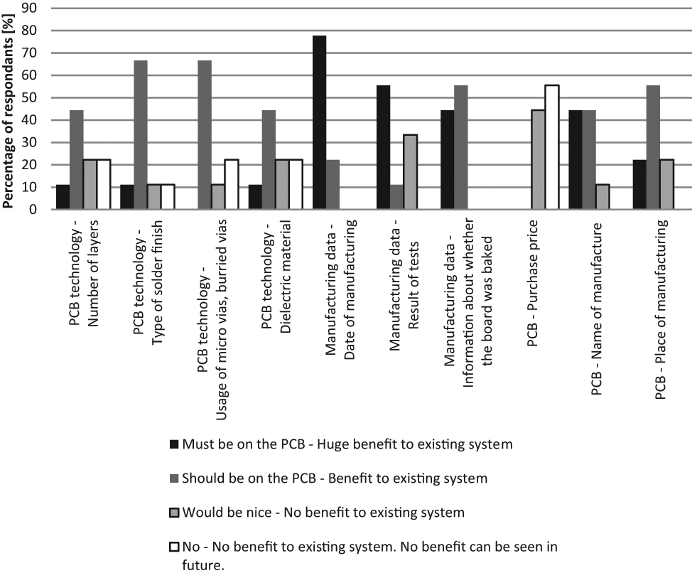
Question 1: What information from the PCB manufacturer is frequently used and should be available directly with the PCB (e.g. in an embedded RFID)?
Less critical in terms of impact (although should be on the PCB) are the location of manufacturing and the PCB technology, i.e. micro-/buried vias and type of solder finish. A typical process from electronics manufacturing at goods inwards is shown in Figure 12. After the board arrives at goods inwards of the electronics manufacturer and the job package has been issued to production by the commercialised product realisation processes, the date of manufacture and customer requests, e.g. special instruction for specific components, boards or materials, are checked. It has to be decided at this stage whether or not the board has to be baked and if so at what temperature. This is a paper-based process and depends highly on the experience of the worker at goods inwards. If the worker is in doubt, he has to consult the engineering team. Delamination of the board or damaging of vias could occur if the board is baked at a wrong temperature. This could cause failures during manufacturing or during field operating of the final product. An embedded RFID tag, which has date of manufacture, baking temperature and PCB processes already stored by the board manufacturer in a tag could significantly enhance this process. The PCB could be scanned at goods inwards and automatically provide the information about the board and its required baking temperature. Incorrect decisions about the baking temperature could be avoided and time for the decision making reduced.
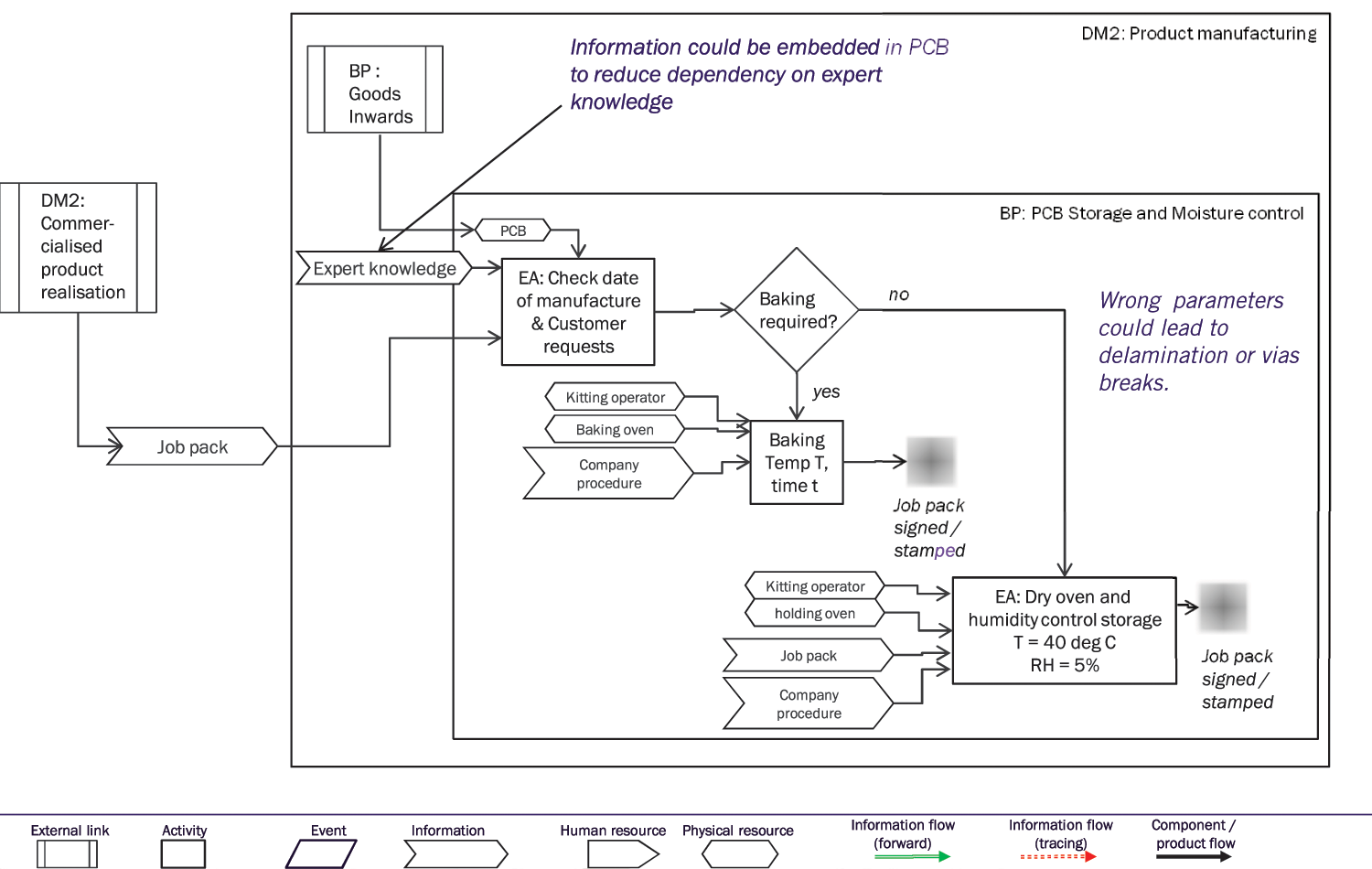
PCB preparation after goods inwards.
The required information to respond to customer requests is illustrated in Figure 12. As shown in Figure 13, all of the information (i.e. time of manufacturing, results of process tests, used component batches, date of PCB manufacturing and name of PCB manufacturer), apart from the BOM, is seen as advantageous to be stored on the PCB. The typical ‘CA’ process undertaken by electronics manufacturers when addressing customer requests is shown in Figure 14. The majority of the activities involved in this process are related to the locating and reviewing of (possibly archived and paper-based) ‘in-house’ documentation. This documentation enables the information and ‘order and purchase’ details provided in the ‘customer report’ to be understood by a ‘quality engineer’ (or team of quality engineers) and enables the CA problem to be described in a paper-based report. Manufacturing details are then sourced by ‘production engineers’ based upon the information in this CA report.
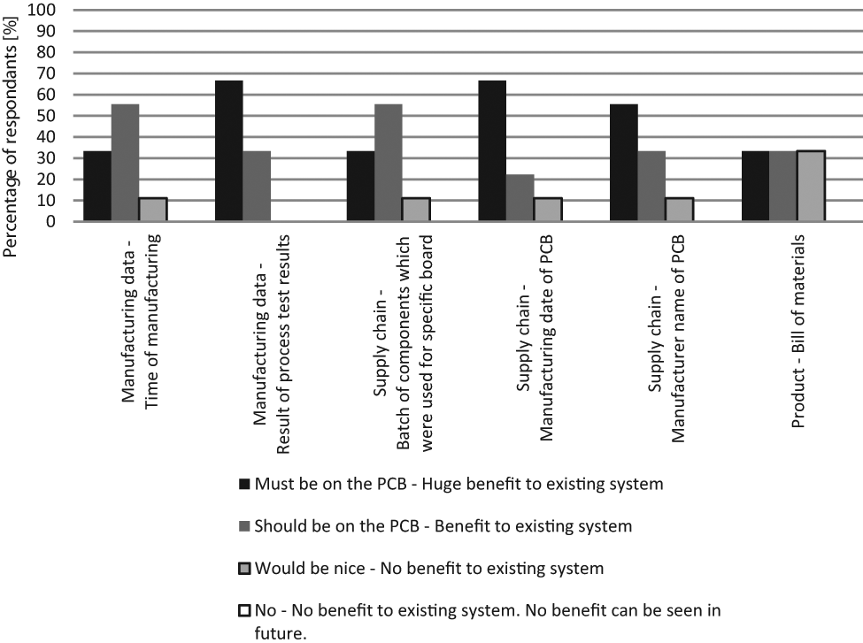
Question 2: When dealing with customer requests, what information is frequently used and should be available directly with the PCB (e.g. in an embedded RFID)?
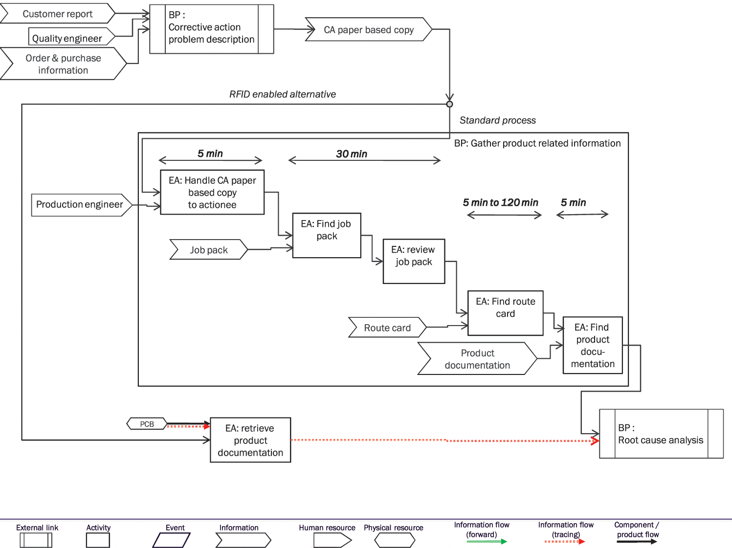
Typical process activities, which are involved in the corrective action business process.
Three main sources of information have to be sourced and reviewed within this business process: the job pack, the route card and production documentation. The job pack includes the process steps, special customer instructions and the BOM. The route card contains the process results and process stamps, confirming a process step by the specific operator. The locating of the paper-based information is currently a manual process requiring searches of archives and current manufacturing facilities (if the product is still in work in progress) and can take 45–160 min. The information is vital input to the root cause analysis business process that enables the reason for the customer report to be determined and correction/processes/operations/lessons learned to be reported and disseminated. Alternatively to this manual process, Figure 13 also shows how the business processes change if all product-related information could be retrieved from the product. The business process ‘gather product-related information’ would be replaced by the single enterprise activity ‘retrieve product documentation’. In this activity, the product’s internal RFID tag is scanned by a reader and the acquired data can be directly used for the further root-cause analysis, saving time and resources used in manually searching for this required information.
Opportunities for RFID during electronics manufacturing
The opportunities for increasing quality and reduction of manufacturing costs provided by the storage of information within each product, via an embedded RFID from the perspective of the electronics manufacturers, are reported in this section (see Figure 15). The visualisation of the location of the specific product in the work in progress (WIP), real-time view of processes that the board has completed, real-time view of current test results and operators involved in the processing of the board are ranked highest (classified as ‘huge benefit to existing system’) by electronics manufacturers. Information that should be on the PCB that would of benefit to current business processes include information provided by embedded sensors, i.e. dynamic information, such as tracking of mechanical shocks and recording of the temperature profile to which the product is exposed during the manufacturing processes.
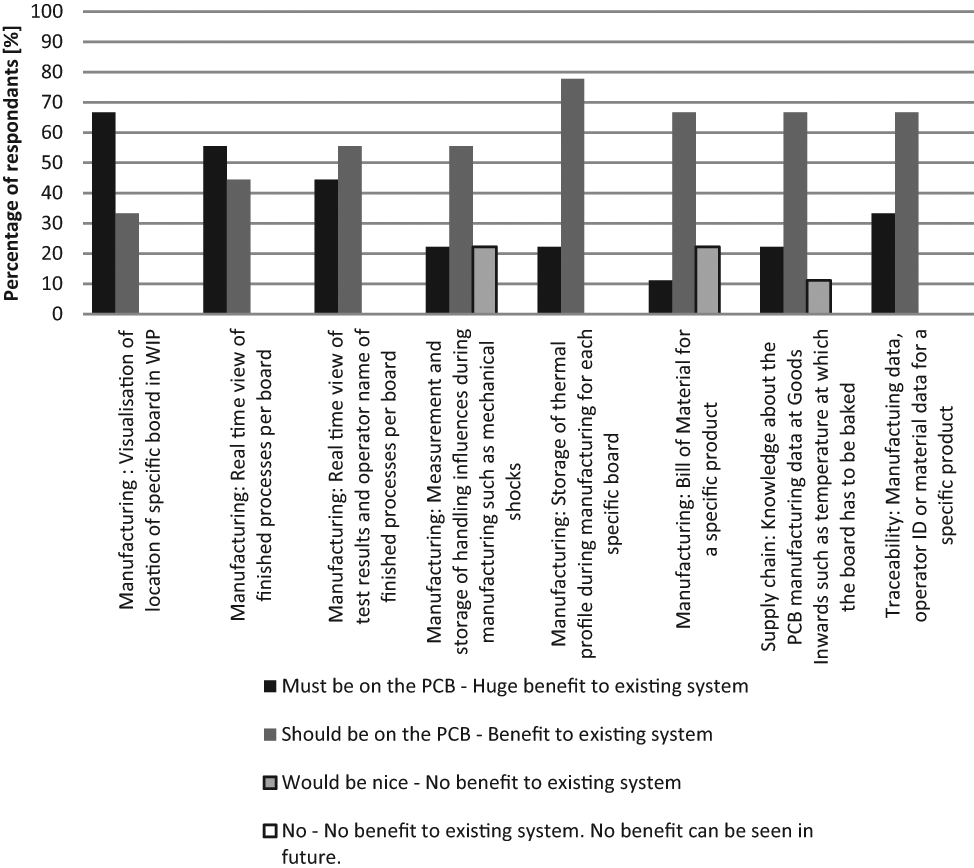
Question 3: Where do you see business opportunities of using an embedded RFID tag into PCBs? How do you rate the opportunity?
The ranking of the benefits of embedded RFID systems in terms of improved manufacturing operations, traceability/quality and supply-chain optimisation is illustrated in Figure 16. The results illustrate that RFID is expected to benefit manufacturing and traceability/quality as compared with current systems with the majority (70% and 60%) of the respondees classifying these operations at level 8 (i.e. ‘very important’). It is interesting to note that supply chain optimisation appears to be of less importance to the electronics manufacturers (which is perhaps not unexpected considering the internal manufacturing centred roles of the people who undertook the survey).
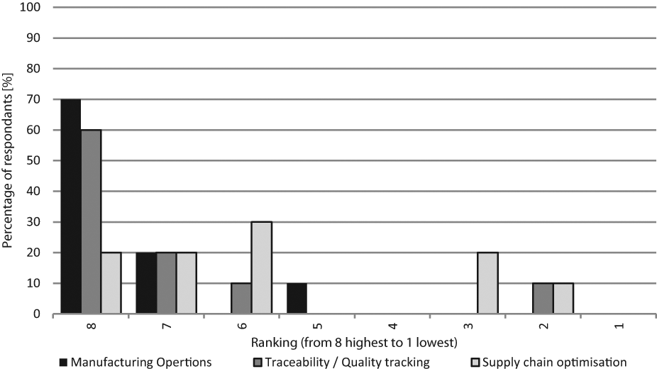
Question 4: How much could you benefit from embedded RFID? (8 means ‘very high benefit compared with existing system’; 1 means ‘no benefit at all’).
Barriers for RFID in electronic products
Opinions among the experts are split on potential barriers to adaptation (Figure 17). Main worries of embedded RFID tags appear to be customer refusal to enable the RFID tag to being embedded within the product and that system costs are higher. If customer concerns exist, an alternative implementation comprising of the embedded RFID tag implementation on the production panel could be realised (possibly in the form of a removable PCB strap that can be snapped off and archived before the product is dispatched to the end customer). Full advantages for manufacturing operations could be achieved from PCB manufacturing to electronics manufacturing while customer concerns are still being accounted for. Opinions are neutral on barriers owing to industry and government regulations, and the reliability of the system. This is understandable considering the maturity of the research concepts and the experience of the experts in embedded RFID systems.
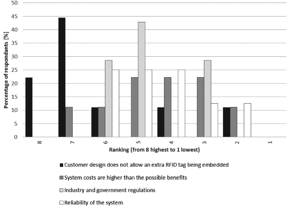
Question 5: Where do you see barriers for the usage of a system with embedded RFD tags? (8: means the barrier is very high; 1 means no barrier existent).
Current usage of information tracking
State-of-the-art information tracking in electronics manufacturing is accomplished by using MES and ERP. The systems are used with focus on scheduling jobs, optimising and monitoring processes, and tracing components and quality data for every board. This information tracking process, however, is mostly constrained to the company barriers. Only data, which was entered or imported to the local company system, can be used during manufacturing or quality processes.
Components and PCB tracing
A typical process for data input at goods inwards is shown in Figure 18. Packages of delivered PCBs or components are scanned, if barcode identification is available on the packaging. The specific product is added to the local database, together with the information from the dispatch note, which has to be typed into the system manually. Once the data is in the system it can be used for warehouse management, production scheduling or WIP visibility. However, life-cycle information, such as special instructions, customer requests or test results from PCB manufacturing, are not always provided and if so, it is structured in non-standardised formats, such that it cannot be imported to the database structure.
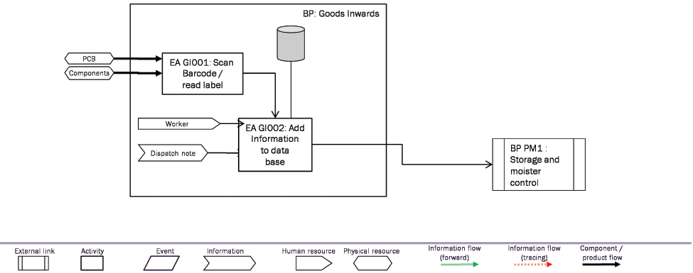
Data entry at goods inwards.
The SMT component kitting and set-up business process, and how it is linked to the paste printing and pick and place business processes, is shown in Figure 19. The SMT component kitting and set-up business process starts by loading the program of the specific board by the operator. The kitting worker selects the specified components and updates the database, so that it is marked that these components are being used for the loaded program. Component reels are generally equipped with barcodes, which enables a complete scanning of the reels when the database should be updated. After the feeders are selected, they are loaded with the issued components. The feeders hold the components for the pick and place machine for a specific job. Feeders can be changed in the pick and place machine just before a job starts. This allows an offline kitting of the feeders and quick changeover between jobs, by changing the feeders. In the last enterprise activity, the feeders are checked, before they can be used during the SMT side 1 business process, which includes the pick and place. The PCBs enter the business process paste printing in which the solder paste is applied to the PCB. The PCB is inspected afterwards to verify if sufficient solder paste was applied to all pads. The PCBs move to the pick and place machine in the business process SMT side 1 after the solder paste inspection. The feeders are then also loaded to the pick and place machine.
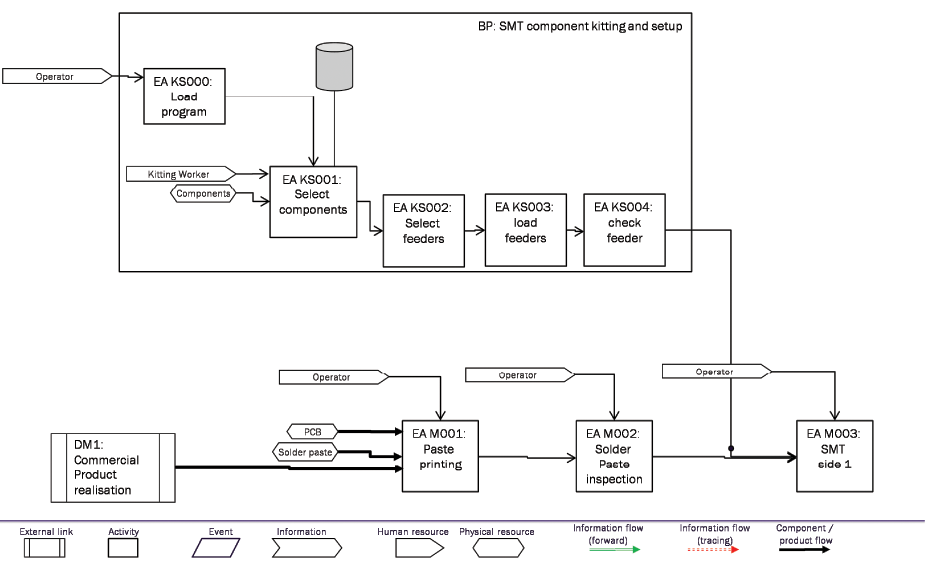
Component kitting process during the surface mount processes.
Fidusial cameras are used to align the boards during solder paste application, pick and place of components and automatic optical inspection. These fidusial cameras can be used to identify products during manufacturing, if a barcode or two-dimensional matrix is printed on to the PCB. As the system is updated, the components in the feeders and the PCBs are identified, and the components that were assembled onto specific boards identified.
Results tracking
A comparison of functionalities of state-of-the-art information tracking systems and systems with embedded RFID is shown in Table 1. As illustrated, static information, such as location of the board within the manufacturing line, localisation of related documents and real-time views of finished processes with links to the related operator, can be visualised and tracked with standard MES systems within the company. Component tracing and retrieval of manufacturing data and operator or material data can also be retrieved, if it was (probably manually) inputted into the system. However, dynamic data, i.e. readings from sensors on the board storing mechanical shocks and temperature profiles, cannot be observed and archived with state-of-the-art MES systems.
Comparison of system implementation with standard information tracking systems and local data storage within a RFID tag.
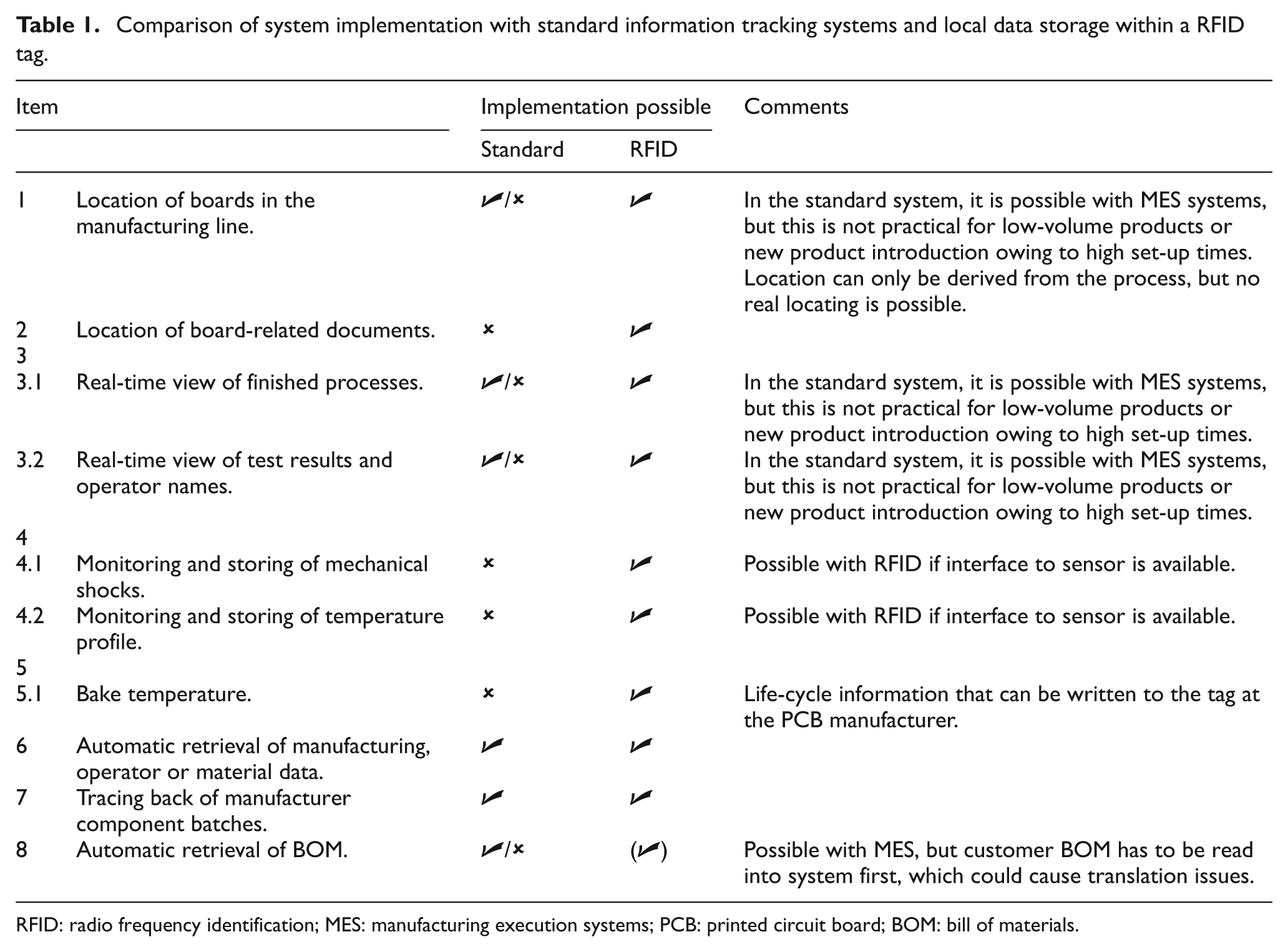
RFID: radio frequency identification; MES: manufacturing execution systems; PCB: printed circuit board; BOM: bill of materials.
Data structure of life-cycle data in embedded RFID tags
As a result of the expert survey a data structure for the embedded RFID tag can be developed. Figure 20 shows the information that was identified as most important to these experts. The static information comprises of the PCB manufacturer, the date of manufacturing, the manufacturer name, the baking requirements and the process results. The dynamic information includes mechanical shocks as events and temperature profile as streaming data. As discussed in the previous section, Class 1 tags are capable of storing the static information. A typical memory structure of a Class 1 generation 2 tag is shown in Figure 19. A unique chip identifier (i.e. TID) can be used to identify the board if the chip is embedded within the structure of the PCB. The name of the customer and product identifier can be stored in the EPC data structure. The user data, which contains 512 bit, can then store additional information. If the characters are stored as 128 bit ASCII characters, 72 characters can be stored in the user memory. In order to store more product-related data, e.g. full process list and design variants, component and material content, a Class 2 RFID tag needs to be used.
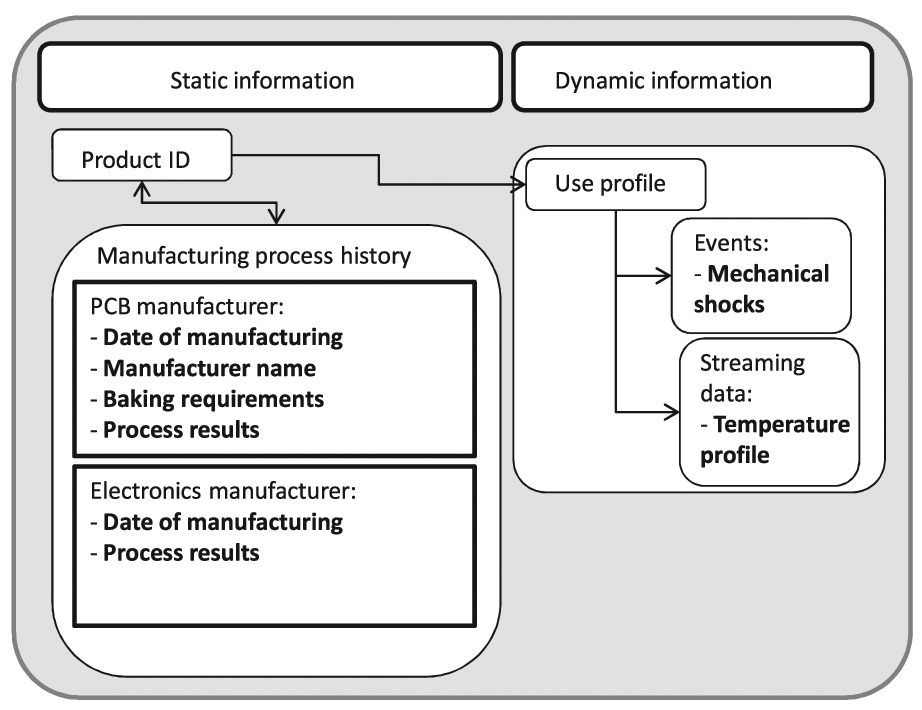
Data structure for an embedded RFID tag in the electronics manufacturing supply chain.
The dynamic information of the product can be acquired with Class 4 RFID tags, which are active wireless components. Acceleration and temperature sensors can be linked to the tag, which saves the dynamic information in its memory.
Conclusions and future research
Competing agile supply chains need visibility of the product process information at item level, at the right time and in the right format, for each specific stakeholder. Product-specific information can be divided into life-cycle information and local information, which is used only internally in a company. It could be shown that the following challenges exist, which create constraints in the information flow during the life cycle of an electronic product.
Information is not individually presented to different stakeholders. Individual information representation is needed to support the different decision makers.
Product-specific information is fragmented over the supply chain of the product.
Linking of the fragmented information is generally possible by cross-company IT systems, but it is mostly not realisable owing to company security policies, set-up and maintenance costs and the short life time of the supply chain.
Full information about the product is not available during the life cycle of the product. This leads to non-optimised decision making, e.g. during manufacturing, servicing, maintenance or end-of-life of the product.
PCD can be structured in two different categories.
Static data: data that is structured at the design stage. This includes unique identification, process times, process identifiers, process results, and location.
Dynamic data: data that is unstructured at the design stage. This includes information about the usage of the product, i.e. streaming data from sensor readings, e.g. acceleration, temperature.
The derivation of the customer needs for a life-cycle monitoring system for electronic products was described in this article. A basic data structure was derived from the results of an expert survey to realise an initial life-cycle monitoring system.
Resulting from the expert survey it could be shown that an initial life-cycle system should include the following data.
Unique identification of the product.
Date of PCB manufacturing.
Manufacturer name.
PCB baking requirements.
PCB manufacturing processes with test results.
Date of electronic assembly.
Electronic assembly processes with test results.
Experts see a big opportunity in visualisation of products in WIP and real time views of the finished processes and test results. The biggest barrier could be the restrictions of the end customers, which could hinder an embedded RFID chip embedded into the final product. A workaround would be the embedding of the tag on a PCB extension, which is removed and archived when the product is shipped to the customer.
A possible data structure is shown in Figure 20. It contains all data that is necessary according to the survey results and business process analysis presented in this paper. A solution in which the chip is embedded within the structure of the PCB is preferred to fulfil all technical requirements, which arise from the customer needs as described in this paper.
Footnotes
Acknowledgements
The authors wish to express their gratitude to the project partners, Invotec Ltd, STI Ltd, GE Aviation, Ford UK, C-Tech, RIB Technologies and SIMS Ltd, for their collaboration.
Funding
This work is supported by the Technology Strategy Board (TSB) and the Engineering and Physical Sciences Research Council (EPSRC) under the INBOARD (award TP11/HVM/6/I/AB138G) and EMBLEM research proposals.