
Abstract
This article presents the software development for a vision-based pick-and-place robot to provide the computational intelligence required for its operation. It follows a client-server control architecture and aims to expand the applications of simply PC-based mechatronics systems to achieve distributed and flexible control through the introduction of a multi-featured and application-suited control unit in the form of a microcontroller as a client to the PC-based server. The system includes a five degree-of-freedom pick-and-place robot whereby a vision system is incorporated in its workspace to identify workpieces with respect to their shape and color. On user specification of the class of workpiece to be manipulated through a graphical user interface, the robot performs the manipulation. A personal computer, operating under the Windows platform, carries out all vision related processing and motion planning for the robot. On request, relevant motion information is communicated through the parallel port of the computer to peripheral interface controller (PIC) microcontroller, which interfaces with the sensing and actuation devices for robot control. The development of the system sees the integration of a number of technologies to achieve a customized control unit including: a vision system, actuation and sensing devices for precise motions, personal computer, microcontroller, and enhanced parallel port. In addition, a layered approach towards software development enables reusability, maintainability, and testability of the system through data abstraction.
Introduction
A mechatronics system is basically a mechanical structure with actuation and sensing devices that are interfaced to a control unit. 1 The control unit acts as the brain of the system and appropriate software programming provides the computational intelligence required for functionality of the system.
PC-based systems are commonly used for control of robotics and mechatronics systems and one such example is given in Lee and Mavroidis. 2 Computer numerical control (CNC) machines, which are essentially a mechatronics system, are another application of PC-based systems in the manufacturing industry. One such work involving the in-house development of a PC-based CNC drilling machine is given in Onwubolu et al. 3 It uses the PC as a front-end interface for a customized machine control unit (MCU) to control a drilling machine using actuation and sensing devices through the parallel port of the PC. The use of a PC in such a way, together with continuous advancements in computer technology, helps minimize the use of hardware components using appropriate software techniques, thus reducing costs and increasing control flexibility. 3 However, the functional expandability of a PC-based system can be limited on its own, unless additional control unit(s) with application-specific requirements is introduced. 4
This work supplements the PC-based system of Onwubolu et al. 3 with an additional control unit to achieve a customized control unit for intelligent, flexible, and distributed control of a vision-based pick-and-place robot. It maintains a PC-based front-end interface system, however, the PC is now used as a server that gives instructions to a client on the tasks to perform, thus making it a client-server model. The use of an additional control unit, a microcontroller, as a client, gives added advantages, such as a higher number of input and output pins to interface with the increase in actuation and sensing devices required in this work. It also eliminates the need for an external analogue-to-digital convertor (ADC), required to interface with the analogue force sensor used in this work, with the availability of an inbuilt ADC in the microcontroller.
However, the use of the client-server model is not limited to the hardware benefits of the client. Client-server based control architecture finds profound usage in similar applications, some of which can be found in Berger et al., 5 Kubitz et al., 6 Peng et al., 7 Shin et al., 8 and Song et al. 9 The approach taken in this work is similar to the use of a client-server control for a mobile robot given in Berger et al. 5 and Kubitz et al., 6 where communication between the client and server makes use of classes to give a layered, modular access to the sensors and effectors of the robot. The interprocess communication between the server and client layer are event driven for fast interaction for real-time control. Similar work is also carried out in Peng et al. 7 where a charged-coupled device (CCD) vision sensor is used for navigation, with image segmentation based on HSV (hue, saturation, value) color mode, while a client-server architecture is used for motion control of a mobile robot.
Although most of these client-server systems are operated wirelessly and/or between two computers, the concept in the architecture remains the same. Such a model allows task distribution between the server and client together with data abstraction. In addition, a layered approach towards software paradigm enables reusability, maintainability, and testability of the system.5,6
The mechatronics system for which the control architecture is presented in this article has been developed in-house10–11 to be eventually integrated into a smart flexible manufacturing system (SFMS) for pick-and-place operations. The SFMS also includes a workstation in the form of a CNC drilling machine 3 operated over the internet 12 and an automatic guided vehicle (AGV) for transporting workpieces in the manufacturing work-cell. 13 While the AGV will transport workpieces to the workstation, the pick-and-place robot will be used for unloading workpieces from the AGV to the workstation.
System overview
The control architecture for the vision-based pick-and-place robot follows a client-server model, though not operated over a network as with conventional client-server systems, the framework for this is given in Figure 1. The PC does all vision-related processing and motion planning for performing the pick-and-place operations and is designated as a server. The relevant motion information is then communicated through the enhanced parallel port (EPP) of the PC, via an interface card, to a peripheral interface controller (PIC), designated as a client, waiting for instructions from the server. The client interfaces with the actuation and sensing devices of the robot to perform the task instructions from the server. The three main phases of software development: vision processing, motion planning, and robot control, are carried out separately and dependent only on the data output from one phase to the next, although the same processing unit, the PC, is utilized for the first two tasks.
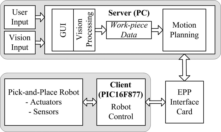
Client-server framework. 11
The vision system is integrated into the workspace of the robot to recognize the shape (rectangle, circle, or triangle) and color (red, green, blue, yellow, or black) of workpieces on the workplane of the robot. Based on the shape and color specifications of the workpieces to be manipulated, given by the user through a graphical user interface (GUI), the robot then performs the pick-and-place operations. Starting from its home (default) position, the five degree-of-freedom pick-and-place robot uses its two-finger gripper to pick specified workpieces from arbitrary positions on its workplane and placing it at a predefined place position with simple sequential-based control.
MATLAB software is used for all vision-based processing. After feature extraction and classification for shape and color recognition, the output data is saved in two notepad files in the American Standard Code for Information Interchange (ASCII) format. The first file stores information on the class of workpiece to be manipulated and the total number of workpieces in this class. The class of workpiece, in turn, depends on the shape and color specified by the user through the GUI. For each class of workpiece on the workplane of the robot, a second file is created containing its centroid and orientation data.
This information is then read by the C++ coded software, which uses the data to plan the motion of the robot for performing the pick-and-place operation. The first data file is read first to determine the class of workpiece to be manipulated and the total number of workpieces in that class. The second file, which is class specific, is then read for the determined class to get the centroid and orientation of the workpiece(s) for motion planning. During motion planning, the required motions are instantly communicated to the PIC microcontroller, PIC16F877 to be specific, through the parallel port of the PC.
The C coded microcontroller uses the actuators, stepper and d.c. motors, the sensing devices, a force sensor, and a limit switch for the two-finger gripper, to perform the instructions from the PC. Finally, MATLAB is also used for implementing the GUI, which links with the executable C++ codes. More on the development and operation of the vision-based pick-and-place robot can be found in Sharan 10 and Sharan and Onwubolu. 11
The following sections present the development of the vision system, motion planning, and robot control. The advantages of the layered approach, as utilized in this work, are then discussed.
Vision system
Image acquisition
The vision unit consists of an overhead mounted CCD camera (Sony digital video camera (model DCR HC42E)), which is connected via the universal serial bus (USB) port to the PC, which has a 2.4 GHz processor and 512 Mbytes of random access memory (RAM) running under the Windows XP operating system with an available parallel port connection. The camera has a CCD size 1/5 in and an image size of 320 × 240 pixels covering a rectangular workplane with dimensions 348.14 × 261.11 mm, determined using the maximum and minimum reach of the robot. The vision unit also includes a structured lighting system with one 11 Watt compact fluorescent lamp placed on each side of the camera. The rectangular view of the workplane, as seen by the camera, is streamed into the PC and a single snapshot image, which is in the RGB color model with 8-bit of data, is taken for processing on user input through the GUI.
Image processing
Image pre-processing
Image acquisition is followed by image pre-processing. The steps in image pre-processing that were utilized for this work are spatial filtering, 14 grayscale conversion, 14 histogram equalization, 15 and binary conversion. 16 Feature extraction is performed using the binary image, while the spatial filtered image is used for color recognition. A sample captured image in the RGB color model, together with its binary image, are shown in Figure 2.
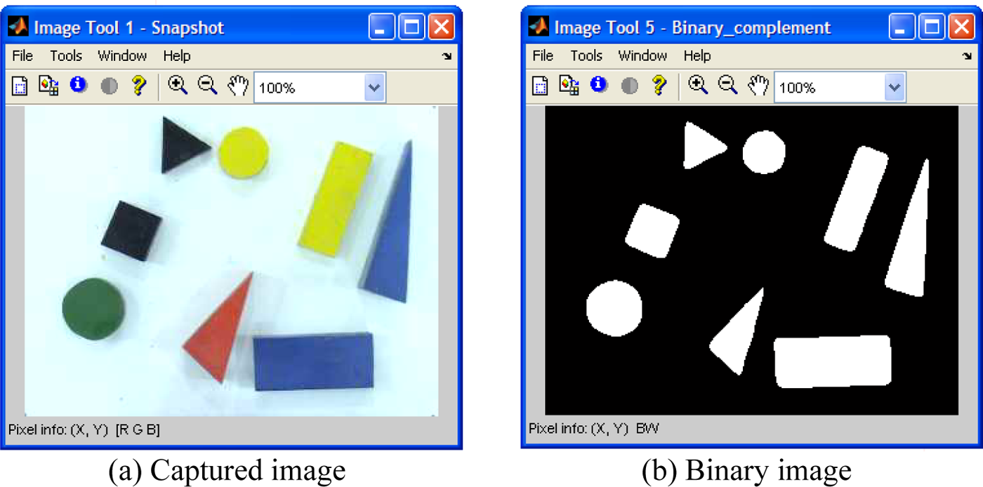
Image pre-processing: (a) captured image, (b) binary image. 11
Feature extraction: centroid
The moment of a workpiece is used to determine its centroid in MATLAB. The basic equation that defines the moment of order (ij) for a two-dimensional continuous function f(x,y) is given in Awcock and Thomas 17 and Gonzalez and Woods 18 as
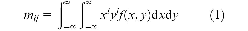
For a digital binary image, this can be rewritten as

where x and y represent the pixel coordinates of the binary image and f(x,y) denotes the corresponding pixel value.
Using moments, the x and y coordinates of the centroid are expressed as

where m00 denotes a zero-order moment, and m01 and m10 denote first-order moments.
Feature extraction: shape recognition
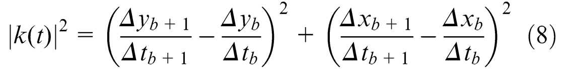
Based on the range of shapes to be differentiated (rectangle, circle, and triangle), the feature of corner detection is utilized for shape recognition. This is a very realistic approach to the problem of shape recognition as it is usually the number of sides or corners that humans use for differentiating these shapes. A corner, as defined in Jain, 19 is a location on the boundary of an object where the curvature becomes unbounded and is given as
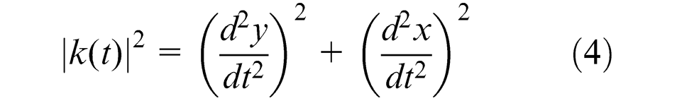
where t represents the distance along the boundary of the segmented regions and a corner is declared whenever |k(t)| assumes a large value.
Equation (4) can be modified for a digital binary image. Letting

and

where xb and yb are the x and y coordinates of the boundary pixels and s is the sample length of the curvature in pixels and with the approximation that the length of the curvature is given by

the curvature of a digital binary image is given as
A sample length of five pixels was chosen, after experimenting with different sample lengths, for best results. The curvature for a sample rectangle, circle, and triangle sampled at five pixels is shown in Figure 3. The four and three outstanding peaks in Figure 3(a) and (c) correspond to the corners of a rectangle and a triangle, respectively. For a circle, Figure 3(b), the non-presence of any outstanding peak implies the non-presence of corners.
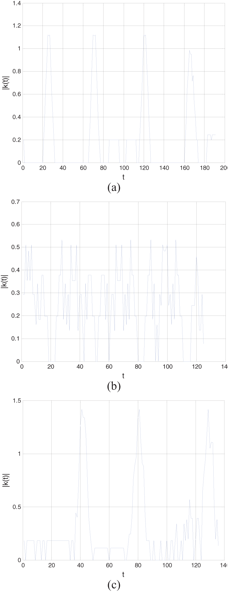
Curvature for a sample (a) rectangle, (b) circle, and (c) triangle. 11
Feature extraction: color recognition
Various color spaces are used for representing color images for image processing. The color spaces HSV and HSI (hue, saturation, and intensity) are a more natural way to how humans perceive color, and is more often used for color image processing than any other color space. 14 Owing to its compatibility with MATLAB, the HSV color space was used for this work. The transformation from the RGB color space, the color space of the captured image, to the HSV color space in MATLAB is given in Rogers. 20
Feature classification – training and testing
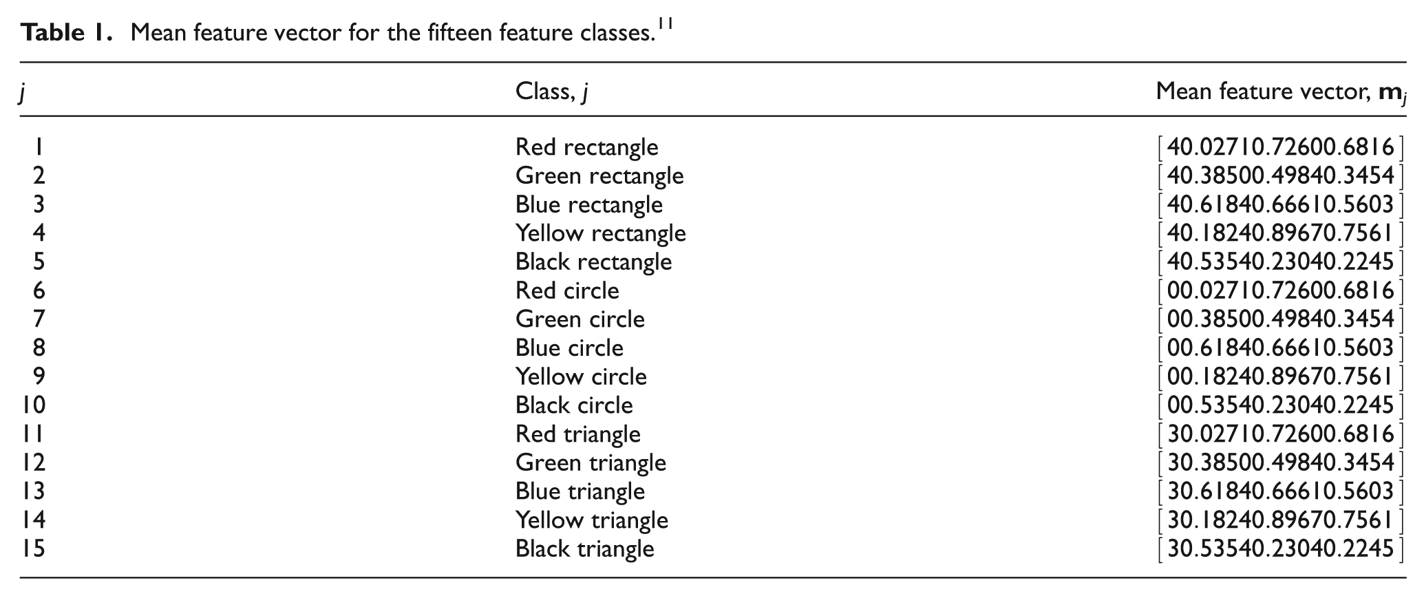
The feature classification system is operated in two modes: training (learning) and classification (testing). In the training mode, a database of images is built that contains known workpieces. Since the number of shapes and colors to be differentiated is three and five, respectively, there are fifteen possible feature classes. For shape recognition, the a priori knowledge on the number of corners is utilized. However, for color recognition, the mean H, S, and V color values are obtained to represent the feature class using samples of 45 workpieces at different locations on the workplane for each color.
The feature vector for workpiece recognition is based on the shape recognition feature of corner detection and the H, S, and V color values as the color recognition features. Therefore, the four-dimensional mean feature vector,

where C denotes the number of corners and H, S, and V the hue, saturation, and value for the jth class, respectively. The knowledge gained from the extracted features forms the database for known workpieces with which the classifier is trained to distinguish the different feature classes in the feature space. The mean feature vector for the fifteen different feature classes is given in Table 1.
Mean feature vector for the fifteen feature classes. 11
Since the feature classes are quite distinct from each other, the simplest approach of minimum distance classification, or Euclidean distance,14,18 was used for feature classification. During experimentation, workpieces were scattered on the workplane of the robot and each time their shape, color, and location was successfully determined.
Vision data
The first output data file for vision processing, Class.txt, stores the class of workpiece j that has to be manipulated, as specified by the user through the GUI, and the total number of workpieces in that class N as a 1 × 2 vector given as

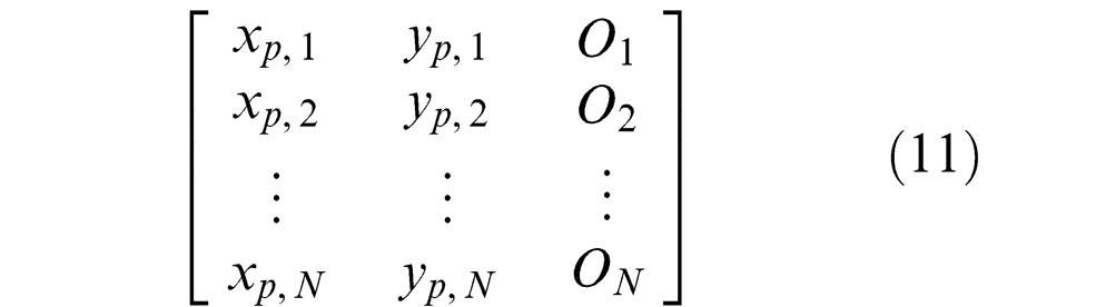
All the workpieces on the workplane that belong to the same class have information regarding the coordinate of the centroid (xp, yp), given in pixels for the 320 × 240 pixel image, and angular orientation O saved as a N × 3 vector in a file named Class_j.txt as
User interface
The GUI provides a medium for the user to operate the pick-and-place robot. The developed GUI is shown in Figure 4. It offers four options in the form of analyzing the workplane (Analyze Workplane), manual mode operation of the robot (Manual Mode), stopping the robot during manipulation (Stop Manipulation), and automatic mode operation through specification of the shape and color of the class of workpiece to be manipulated.
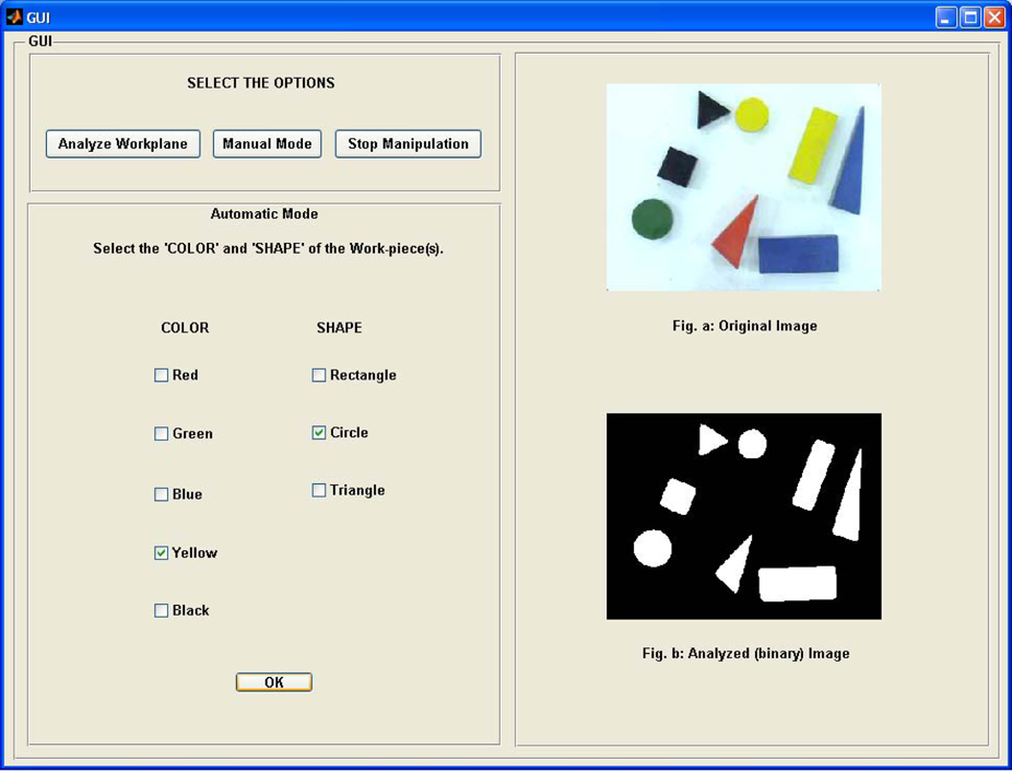
An overview of the GUI.
The analyze workplane option captures an image of the workplane and performs analysis to differentiate the workpieces but does not perform any motion. This feature would be especially handy if the system is used for teleoperation, similar to that of the CNC drilling machine that has been presented in Lal and Onwubolu, 12 whereby remotely located users would be able to view the analysis over the internet before performing the manipulation.
Moreover, an added feature is that there are some restrictions on performing the manipulations and an error message is displayed if the user violates them. The first case of error is when the user tries to perform manipulation without specifying the shape and color of the workpiece(s). The other case is when there are no workpieces on the workplane matching the shape and color specified by the user.
Motion planning
The C++ coding, executed automatically once the vision data has been saved, then reads this stored data to plan the motion for performing the pick-and-place operations. The flowchart for C++ coding is given in Figure 5.
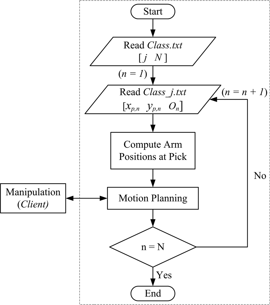
Flowchart for C++ coding.
Read data
The C++ coding initiates by reading the two data files. In the sample data shown in Figure 6, the class of workpiece is one and there are two workpieces in this class with centroids (65.58, 161.32) and (149.26, 227.29) with orientation of −41.91° and −87.35°, respectively.
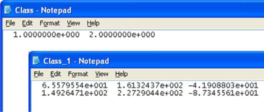
Sample workpiece data.
Data conversion and motion planning
The pixel coordinates are then converted to the robot coordinate system to compute the angular position of the arms at the pick position only, as the home and place positions are predefined, using inverse kinematics followed by motion planning. 10 For conversion of the coordinate system, the camera is first calibrated by focusing it to cover the area of the workplane and then determining the distance covered by a pixel on the workplane in each direction. This approximation was used since the camera and workplane locations are fixed and the thickness or height of the workpieces is small. Finally, the base joint of the robot was used as the origin to convert the pixel coordinates to the robot coordinate system.
The four possible set of motions of the robot are home to pick, pick to place, place to pick, and place to home, as shown in the flowchart of Figure 7. The clearance position is an intermediate position between the pick and place positions. Since the pick and place positions are at the same height, the clearance position ensures that the gripper is raised above all workpieces when moving to/from the pick position from/to the place position. The pick and place operation will continue until all the workpieces in the chosen class have been manipulated, after which the robot returns to the home position.
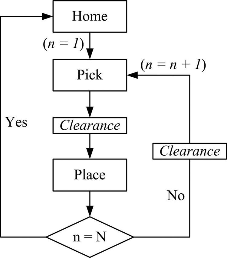
Motion planning. 11
The C++ functions for these four set of motions are
void Home_to_pick();
void Pick_to_place();
void Place_to_pick();
void Place_to_home();
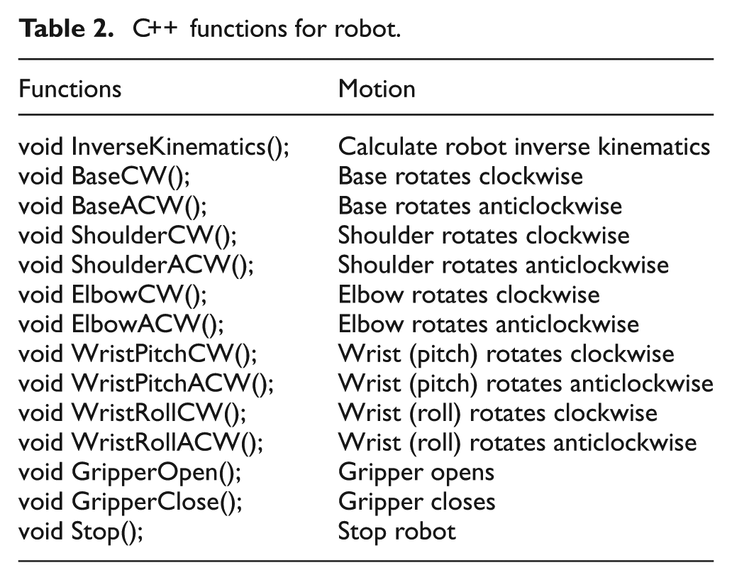
The joint to be rotated, its direction of rotation, and angle of rotation is communicated to the client in a sequential manner for the base, shoulder, elbow, and wrist (pitch and roll) motions. However, for the gripper, the instructions are only to either close it or open it. The PIC then uses the limit switch and the force sensor mounted on the gripper to control the opening and closing of the gripper, respectively. The C++ functions for the robot are explained in Table 2.
C++ functions for robot.
Robot control
Client overview
The PIC16F877 microcontroller, manufactured by Microchip®, 21 has been used for interfacing with the sensors and actuators for robot control. It was housed on a bootloader board 22 for ease of programming. The PIC16F877 offers 33 input/output pins that are easily able to connect to all the actuators and sensing devices when compared with the 16 input/output pins offered by the EPP interface card. 3 It also offers external interrupt feature, pins B4–B7, which allows prompt detection of change in input state. This feature was used for reading data from the server as soon as it is made available.
Furthermore, PIC16F877 has an in-built ADC, available on pins A0–A3, which eliminates the need for an external ADC for the analogue force sensor. In addition, except pin A4, all pins have transistor–transistor logic (TTL) input levels and full complementary metal oxide semiconductor (CMOS) output drivers making it compatible with the interface card.
Client-server communication
The communication between the client and server is event driven, where the client initiates the data transmission when it is not busy. There are seven lines used for communication between the server and client through the parallel port with an interface card 3 as the medium. Table 3 gives the description of these lines.
Interface card pin functions.
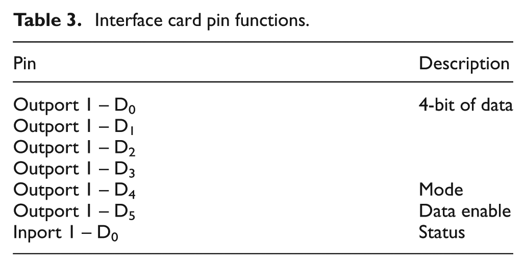
The first four lines of the 8-bit outport 1 of the interface card are utilized for sending the actual data to the client. The mode pin indicates whether the data is for automatic mode or manual mode operation of the robot. Manual mode operation is where the user uses assigned keys on the computer keyboard to control individual motions of the robot. In automatic mode operation, manipulation is carried out autonomously where the user only specifies the shape and color of the workpiece to be manipulated through the GUI. The last output line, data enable, goes high whenever there is new data output on the data lines.
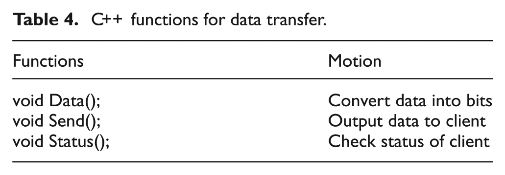
The status pin is an input connection to the server from the client that is used to indicate its state to the server. The C++ functions for data transfer are given in Table 4.
C++ functions for data transfer.
Manual mode operation
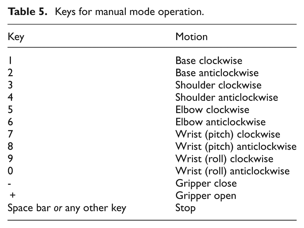
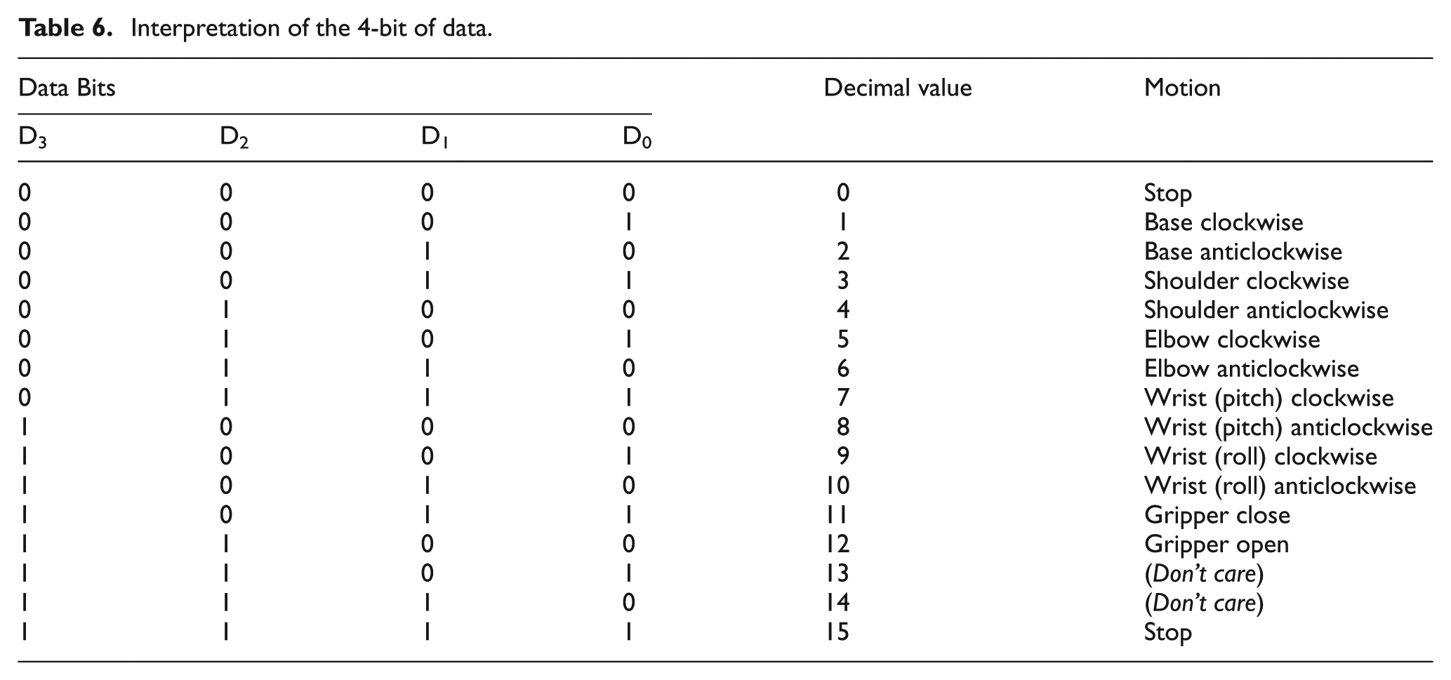
The manual mode operation of the robot eventuates on user inputs from the computer keyboard after this mode of operation has been specified through the GUI. Table 5 lists the keys and the respective motion they are associated with. The PIC16F877 continuously actuates the specified joint on an input by latching the data until a new data is received. The 4-bit of data communicated to the client for each motion in manual mode operation of the robot is given in Table 6.
Keys for manual mode operation.
Interpretation of the 4-bit of data.
Automatic mode operation
Figure 8 shows the timing diagram for data transfer between the server and client in automatic mode operation. Initially, the status pin is high indicating that the client is ready to receive data. The server then sends the first set of data, which contains information regarding the joint to be actuated and its direction of rotation, while activating data enable. This 4-bit data is similar to that given in Table 6.
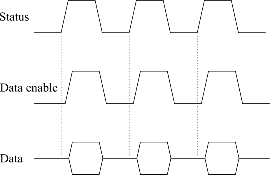
Timing diagram for data communication in automatic mode.
The next data to be communicated, followed by the rising edge of the status signal, is the angle of rotation of the respective joint, except the gripper. The maximum angle data that can be sent at an instance is 4-bits, however, the maximum angle of rotation can be up to 8-bits. This is achieved by sending 4-bits of data twice. The client then goes on to perform the task at hand, keeping the status pin low to indicate it is busy. After completing the task, it again activates the cycle of communication by activating the status pin. It takes approximately 33 ms for one set of data to be communicated to the client by the server, which is reasonable for sequential-based control of the robot. Unlike the automatic mode operation, the data enable and status pins are not utilized in communication for manual mode operation. Figure 9 shows the robot during an autonomous pick-and-place operation.
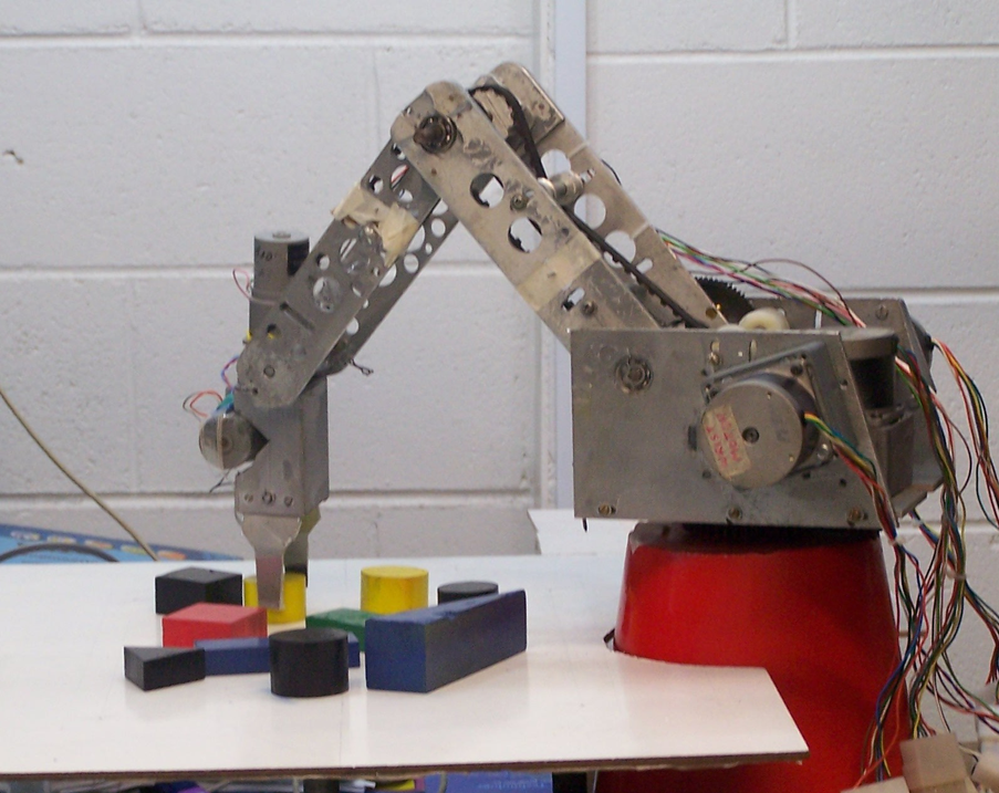
Robot during autonomous manipulation. 11
Layered approach
The operation of this system has been broken down into pieces that are smaller and more manageable than conventional systems to make this system modular using a layered approach. Using a top-down approach, the overall functionality and features of the system were determined and separated into the following components: vision processing, motion planning, and robot control. The bottom layer also allows hardware interface while the top layer the user interface.
The architecture presented here offers two additional layers when compared with the CNC drilling machine. 3 The CNC drilling machine has no automatic way of determining the drilling coordinates. An additional layer for this system, in the form of a vision system, gives it added intelligence to locate and differentiate workpieces on the workplane of the robot. However, although the same processing unit, the PC, is used for vision-related processing and motion planning, their organization in two separate layers ensures data abstraction.
The second additional layer, robot control, is realized in the form of a client-based microcontroller, an additional control unit when compared with simply PC-based systems, which allows task distribution between the two control units with application-specific control. It also offers benefits, such as increased input and output pins to interface with the increased electronics hardware, together with in-built ADC for reading the analogue force sensor. Moreover, for speed control of the drill motor in the CNC drilling machine, an external circuit was designed involving a d.c. motor control unit and a digital-to-analogue convertor (DAC). The PIC16F877 has two pins (C1 and C2) available as capture, compare, and pulse-width modulation (PWM) (CCP) generation mode. This feature can be utilized for speed control of d.c. motors minimizing hardware usage with equivalent software control. The usage of the client in this work can also be further expanded for speed control, if required in future.
The major advantage of the layered approach is the simplicity of software construction and debugging. The layers have been chosen such that each uses functions and services of only lower-level layers, which simplifies debugging and system verification. This also means that a layer does not need to know how these operations are implemented, but only what these operations do. Each layer does not share the existence of certain data structures, operations, and hardware from higher-level layers. Therefore, each layer can be reused, maintained, and tested on its own.
Conclusion
The control architecture for a vision-based pick-and-place robot has been presented, which is based on client-server model. A PC is utilized as a server that interfaces through the parallel port to a PIC16F877-based client unit. The PC carries out work in two layers, vision processing and motion planning, with the GUI linking the two layers. The third layer, robot control, is implemented in the client, which also interfaces with the robot hardware, actuators, and sensors.
The separation of this work into the three layers allows each component to be tested and maintained on its own through data abstraction. It also means that each layer can be reused or replaced for other similar applications, such as involving a vision processing unit that employs some other form of workpiece recognition as long as the output data format is the same as that for the current system. This would imply no change to the motion planning and robot control architecture of the system making the architecture more versatile.
Footnotes
Funding
This work was funded by the University of the South Pacific under research grant 6C066.