
Abstract
In the tube hydroforming process, friction in the guiding zone often affects the axial feeding process. In this article, the effect of the main factors on friction force were analyzed first according to the force analysis model proposed. Based on the idea to reduce friction force by decreasing the contact area, a new punch structure was proposed. A testing tool was developed to evaluate the feasibility of the new structure. Results show that the length of the guiding zone, the stress state and the friction coefficient are three main factors that determine the effect of friction force. The ratio of friction force to punch load will increase rapidly as these three factors increase. By using the new sealing and guiding structure, about 30% of the punch load can be reduced. The use of a polyurethane ring in the gap between the tube and die can reduce friction force greatly if the bulge forming of the tube tends to occur in the guiding zone.
Introduction
In tube hydroforming, tribology plays a very important role because of the high contact pressure and large contact surface on the tool–workpiece interface. As pointed out by Koc and Altan 1 and Vollertsen et al., 2 the reducing of friction force between the tube and die cavity is one of the major tasks in tube hydroforming, especially when considerable axial feeding is required. In general, friction force is determined by contact pressure, contact surface area and the coefficient of friction (COF), if relative sliding occurs between tube and die. Therefore, many efforts have been made to reduce the friction force from these aspects. Groche and Peter 3 investigated the performance of different lubricants in the tube hydroforming process. Koç 4 discussed the selection of lubricant in industrial applications.
Evaluation and improvement of tribological conditions in tube hydroforming have been widely investigated. Vollertsen and Plancak 5 discussed the possibility for the determination of the COF in tube hydroforming. Possible testing methods of the COF in the expansion zone and feeding zone were given and analyzed. For the expansion zone, the COF can be measured by tube expansion test, tube upsetting test or direct measurement method. However, no standard test seems to exist for this region. For the feeding zone, a so-called ‘push-through’ test is often used. 6 This method is based on the assumption that the tube material is pushed without plastic deformation and consequent thickness change, and the contact pressure is an even distribution and is equivalent to the inner pressure. In practice, however, the tube in the feeding zone is flared at the ends and local thickening tends to occur. This will all affect the accuracy of the push-through test. Ngaile et al.7,8 studied the lubrication mechanisms in the transition and expansion zones in tube hydroforming. Model tests were developed to evaluate lubricants and die coatings in different zones. For the transition zone, the model test was based on the limiting dome height (LDH) test principle. For the expansion zone, a pear-shaped tube expansion test (PET) was developed.9,10 Owing to the difficulty of attaining the hydrodynamic effect in the transition and expansion zone, a dry film lubrication seemed to be the best choice for these regions.
Geiger et al. 11 proposed a new method to eliminate friction force in the feeding zone, by using a high viscous fluid flowing along the internal and external surface of the tube. The flow of viscous fluid helps to reduce the friction force and allows sliding between the tube and the die surface. Local heat treatment was also used to reduce flow stress in the expansion zone. The presented procedure allows the production of complex tubular parts, even with a long guiding zone. However, the die structure is complex and the separate pressure control is difficult to realize in practice.
In this article, the effect of friction in the guiding zone will be analyzed first. Based on the idea to reduce the contact surface area, a new punch design, with special sealing and guiding structure, will be proposed and tested by experiments.
Theoretical analysis
Force analysis model in guiding zone
In tube hydroforming, the tube can be divided into three different zones, the guiding zone, transition zone and expansion zone. In the guiding zone, the tube will slide along die cavity. The friction force is determined by the contact pressure and contact area. As the difference between the contact pressure and inner pressure is typically in the order of 10%, it is often assumed that the contact pressure is equivalent to the inner pressure.
The forces acting on the tube in hydroforming are shown in Figure 1. The friction force on the tube in the expansion zone is neglected. In the figure,
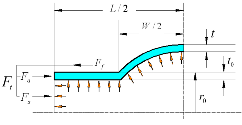
Force analysis in the guiding zone in tube hydroforming.

Assuming no obvious plastic deformation occurs in the expansion zone, then


Define one parameter A, which is described by

then

Define another parameter B, which is described by
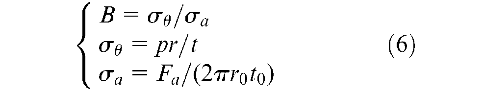
then


Based on equations (2)–(8), equation (1) can be written as

The ratio of friction force to punch load can be calculated as

It can be seen that, at the beginning of tube hydroforming, the effect of friction force in the guiding zone is determined by three factors, the relative length of the guiding zone, the stress ratio, and the COF, which can be presented by A, B and μ, respectively.
Main factors on friction force
According to equation (10), the ratio of friction force to punch load can be calculated, as shown in Figure 2. It can be seen from the figure that the friction force in the guiding zone is small when the friction coefficient is low. As the COF increased, the ratio of friction force to punch load increases rapidly, which means that a large amount of punch load will be wasted to overcome the friction force. For a given COF, the increase of the guiding zone length results in a rapid increase of the ratio. The effect of the stress state is relatively small.
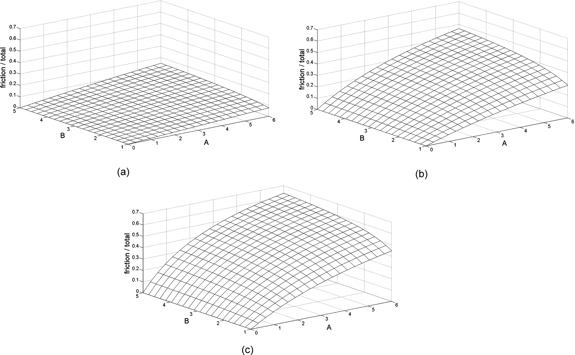
The ratio of friction force to punch load. (a) μ = 0.02; (b) μ = 0.10; (c) μ = 0.20.
New sealing and guiding structure
In order to decrease the friction force in the guiding zone, a new punch with a special sealing and guiding structure is proposed, as shown in Figure 3. In the figure, the tube in the guiding zone is totally separated from the die cavity. In the feeding process, the tube ends will be expanded by the taper surface on the punch. When the tube ends contact with the root of the ring slot, the material in this zone will then be pushed into the expansion zone as the punch moves forward.
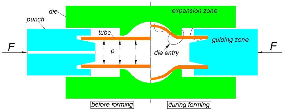
New punch with a special sealing and guiding structure.
Because the contact surface area is totally reduced in the guiding zone, there will be no friction force acting on the tube during the feeding process, and a low punch load will be required.
Experimental
Experiment setup
In order to test the effect of the new punch structure, a special experiment setup was developed, as shown in Figure 4. The tube will be sealed and filled with different inner pressure first, and then pushed down from one end by the upper punch. Both a traditional punch structure and the new punch design can be evaluated using the setup, by changing the upper punch and guiding block.
A 304 mm stainless steel tube, 25 mm in diameter and 3 mm in thickness, was used in the experiment. The total length of the specimen was 200 mm, with 69 mm in the guiding zone. The experiment was carried out on a Instron-5500R universal testing machine. The load and displacement curve of the upper punch was recorded.
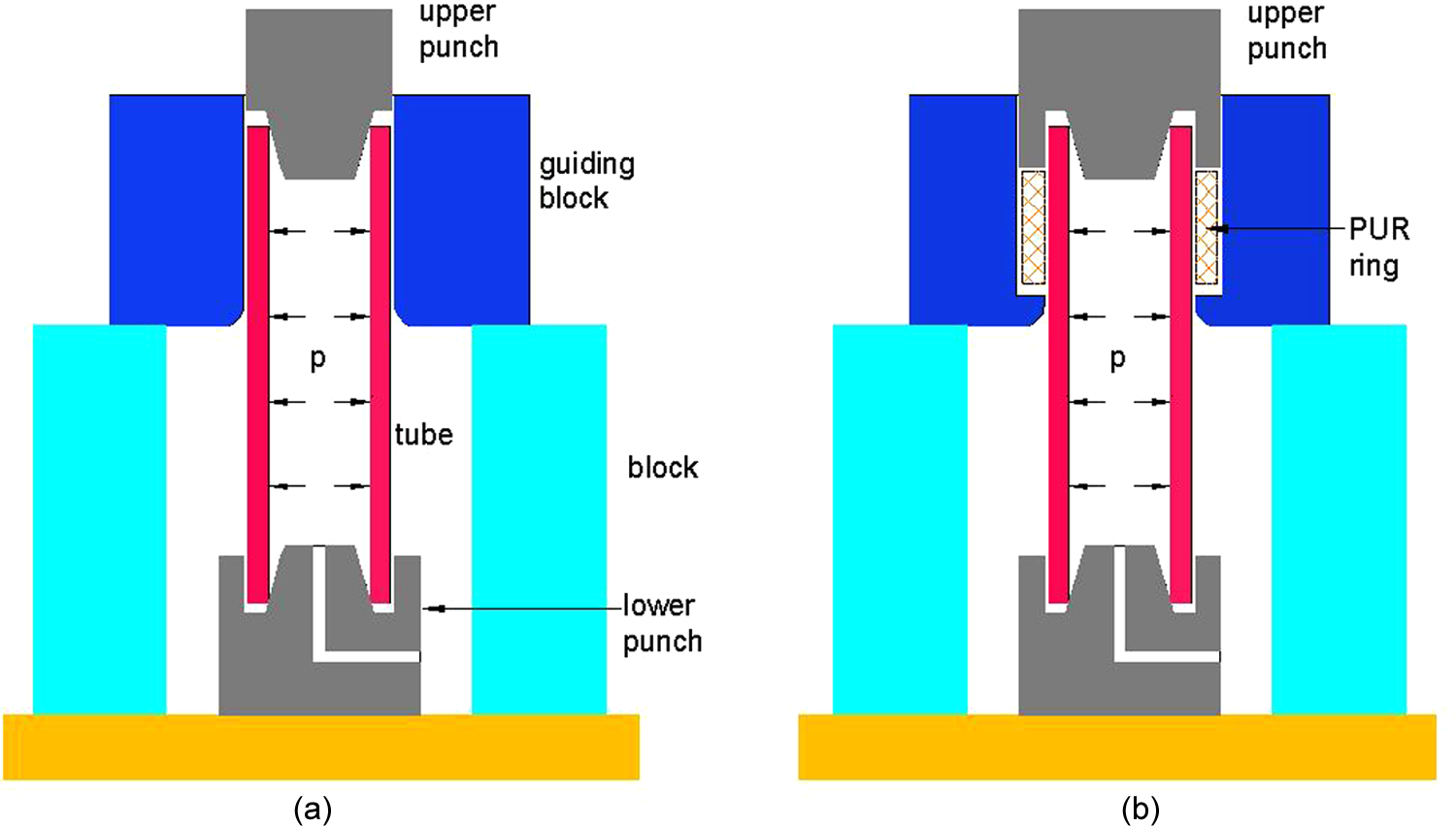
Experimental setup for friction force measuring: (a) old structure; (b) new structure.
Effect of inner pressure
Tests were first carried out with different inner pressure. The recorded load–displacement curves are shown in Figure 5. It can be seen from the figure that the load–displacement curve can be divided into three main stages. In the first stage, the load increased slightly as the punch moved. This is the tube-end expanding deformation. After that, the load increased rapidly. In this stage, the tube is compressed tightly by the punch and the feeding process began. In the last stage, the load increased slightly again and the tube was fed steadily.
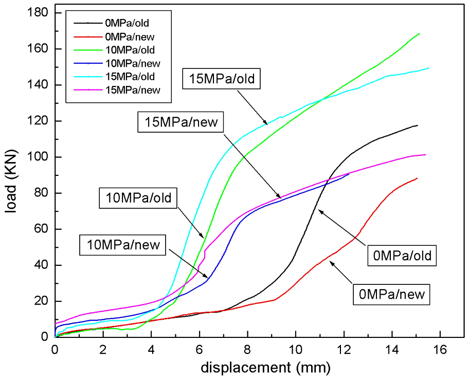
Stroke–force curve for feeding with different inner pressures.
For a given inner pressure, the loads for two different punches in the first stage are close to each other. As the real feeding process began, it is obvious that a much lower load will be required for the punch with a new structure. This means the friction force in the guiding zone has been greatly reduced, assuming that the sealing force and axial compressive force are the same for two punches.
Effect of inserted polyurethane ring
In the new punch structure, shown in Figure 3, when the length of the guiding zone is long, bending or expansion may occur in this zone. These kinds of deformations will all affect the material flow to the expansion zone. In order to avoid the undesired deformation in the guiding zone, suitable inserts may be put in the gap between the tube and die cavity, as shown in Figure 4(b).
In the experiment, polyurethane (PUR) rings with different dimensions were used as inserts. The PUR ring had a 42 mm outer diameter and 27 mm inner diameter. That means a 2-mm clearance was kept on both sides of the PUR ring, to the die cavity and the tube. The height of the PUR ring was 65 mm, 69 mm and 73 mm, respectively. When the ring height is 69 mm, the punch will contact the tube end and the top of the PUR ring together. As for a 65 mm height, the punch will compress the tube end first and then come into contact with the PUR ring. As for a 73 mm height, the PUR ring will be compressed about 4 mm first and then the tube end. By using PUR ring with different heights, the constraint on the tube in the guiding zone can be changed.
Figure 6 shows the load–displacement curves of the tests with different PUR rings and different inner pressures, together with the results of the old punch and the simple new punch without PUR rings. It can be seen from Figure 6(a) that, when tested without inner pressure, the punch loads for the tests with inserted PUR rings are between that of the old punch and the simple new punch. That means, in this condition, the PUR ring can not help to reduce the friction force. On the contrary, additional load is required to compress the PUR ring. In Figure 6(b) and (c), the punch loads for the tests with inserted PUR rings are close to that of the simple new punch at 10 MPa inner pressure. As the inner pressure increased to 15 MPa, these loads became lower than that of the simple new punch.
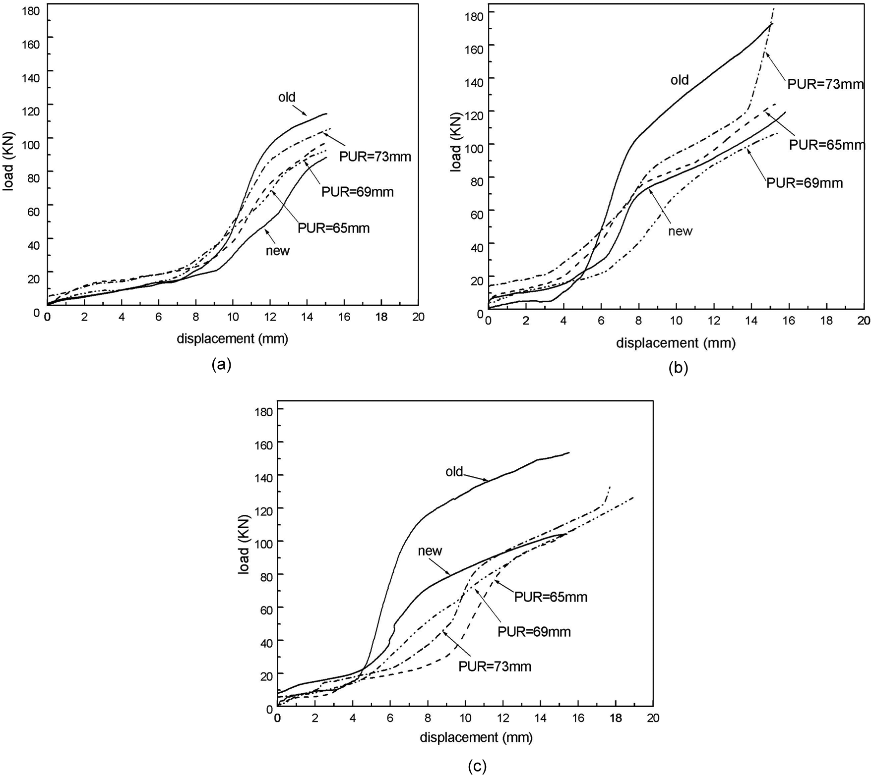
Stroke–force curve for feeding with different PUR rings: (a) 0 MPa; (b) 10 MPa; (c) 15 MPa.
When the tube is filled with high inner pressure, expansion tends to occur in the guiding zone, and it will be difficult to push the material into the middle expansion zone. When PUR rings are inserted and compressed, it can provide constraints from outside and expansion in the guiding zone can be postponed or prevented. It should be pointed out that the effect of the PUR ring at the beginning of feeding is much bigger than that at the end of the feeding process, as shown in Figure 6(c). In fact, at the beginning of feeding, even though the PUR ring was compressed together with the tube, little force was required. When the PUR ring was compressed further and the initial gap between die cavity and tube was totally filled, the counter pressure from the PUR ring increased rapidly. In this condition, the punch load may not be reduced compared with the traditional structure, even though the friction force on the tube can still be eliminated.
Conclusion
The ratio of friction force in the guiding zone to punch load was calculated. The length of the guiding zone, the stress state and the friction coefficient are three main factors that determine the ratio. This ratio will increase rapidly as these three factors increase.
About 30–40% punch load can be reduced by using the newly proposed punch design, as shown in Figures 5 and 6, which is mainly friction force in the guiding zone.
The inserted PUR ring can help to reduce the friction force, especially when forming with higher inner pressure and bulge forming tends to occur in the guiding zone.
Footnotes
Acknowledgements
The authors would like to take this opportunity to express their sincere appreciation to the funding bodies.
Funding
This study was financially supported by the National Natural Science Foundation of China (No. 50805033) and the Natural Science Foundation of Heilongjiang Province of China (No.E200804).