
Abstract
Plastic deformation of sheet metals during forming induces complex residual stresses in the component owing to its geometry and material anisotropy. The residual stresses affect the durability of the components. Fatigue life estimation incorporating the forming-induced residual stresses is limited. In the present work, the state-of-the-art in modelling sheet metal forming, residual stress estimation and fatigue life prediction are reviewed. The challenges in integrating the residual stress owing to forming and fatigue life prediction are brought out. The parameters influencing the sheet metal forming, residual stresses and fatigue are discussed to emphasize the complexity of the present problem.
Introduction
Sheet metal products are increasingly used in a variety of engineering applications. In recent years, light-weighting of automotive structures has gained much attention owing to the stringent fuel economy norms. The sheet metal assembly with residual stresses owing to forming and joining are subjected to road loads in service, 1 which are very different from the ideal constant amplitude load sequences (Figure 1). The cyclic stresses owing to complex road loads lead to early fatigue failure. To compound this, the anisotropy of the sheet metal alters the fatigue characteristics.
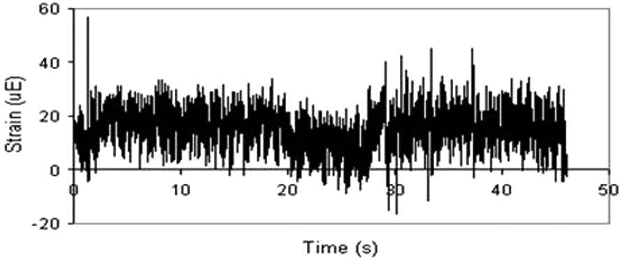
Road data measured on an automotive suspension arm. (Reprinted from Abdullah et al., 1 with permission from Elsevier.)
The forming process alters the stress state of the component, inducing residual stresses. The residual stress plays an important role in the fatigue behaviour of the components. The influence of residual stress in fatigue life is complex owing to its inter-dependency on the various parameters. The advancements in finite element methods allow a reasonably accurate prediction of residual stresses imparted in a sheet metal component during forming. The integration of the predicted residual stresses in fatigue-life calculation is essential for a realistic life prediction of components.
The present development in the modelling of a sheet metal forming process, residual stress prediction and fatigue-life calculation are reviewed and the present-day’s challenges faced by the engineers in integrating the forming effects in fatigue are analysed. The material and process parameters influencing the sheet metal forming and fatigue are discussed before reviewing the advancements on modelling.
Sheet metal forming
Sheet metal forming is a process of imparting a desirable geometry by plastically deforming the material using a set of tools. The sheet metal forming is influenced by the geometry, material and processing parameters.
Effect of material properties in forming
The material behaviour during deformation is influenced by several parameters, including chemical composition. The presence of carbon and nitrogen in a low-carbon steel sheet influences the grain growth during annealing and prevents formation of favourable texture. 2 Elements like titanium, niobium, vanadium and aluminium fixes the free carbon and nitrogen by forming carbonitrides, thereby introducing favourable texture,3,4 which in turn influences the stress distribution during forming. The alloy composition controls the formation of unfavourable precipitates; for example, excess titanium precipitates with sulphur and oxygen to form inclusions.4,5 The inclusions can affect the plastic deformation during forming and further fatigue behaviour. In addition to chemical composition, the processing parameters, like reduction during hot rolling and annealing type, influence the mechanical properties of the sheet metal.5,6 These mechanical properties, yield strength, strain hardening exponent and strain rate sensitivity can be related to the deformation behaviour of the sheet metal during forming.7,8
Among several material properties, the anisotropy induced in sheet metals owing to cold rolling and annealing has a major influence in the plastic deformation and subsequent residual stresses. 9 The yield criteria that indicates the stress state of initiation of plastic deformation is influenced by the anisotropy of materials (Figure 2). Considerable research has been done in developing anisotropic yield criteria and it forms the basis of mathematical treatment of the sheet metal forming process.
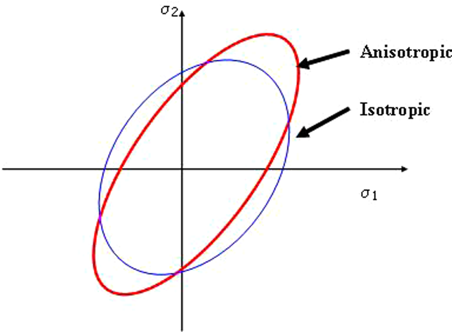
Schematic representation of influence of anisotropy in yield locus.
Constitutive modelling of anisotropy in yield criteria
Hill modelled the yielding and flow behaviour of an anisotropic material (henceforth referred to as Hill 48) by suitably modifying von-Mises isotropic yield criterion. 10 Woodthorpe and Pearce 11 reported conflicting results when using the Hill criterion on certain aluminium alloys. This phenomenon, termed as ‘anomalous behaviour’ led to the formulation of several non-quadratic yield criteria. Hill 12 later proposed a generalized, non-quadratic criterion with four special cases. Hill13,14 further generalized his previous criterion to accommodate a wider range of materials. It may be noted that Hill’s criteria and many other non-quadratic yield criteria are phenomenological in nature and do not reflect the underlying crystallographic basis.15–18
Logan and Hosford 19 proposed a non-quadratic yield criterion (referred to as the Hosford criterion) based on crystallographic calculations. The Hosford criterion does not include a shear stress term. Barlat and Lian 20 overcame the limitation for the plane stress condition (referred to as the Barlat 89 criterion) using stress invariants in a general coordinate system. Barlat et al.21–24 later proposed a series of yield criteria for aluminium alloys. Karafillis and Boyce 25 used a linear transformation rule and accommodated non-orthotropic material behaviour in their criterion. The linear transformation proposed by Karafillis and Boyce was later used by Barlat et al. in their advanced yield criteria.
Independently, Banabic et al. 26 proposed a new criterion for a plane stress condition by extending the Barlat 89 criterion. Banabic et al. 27 modified the criterion by including a biaxial anisotropy coefficient (referred to as BBC 2004). The yield loci predicted by three different criteria, Hill 48, Barlat 89 and BBC 2004 are compared in Figure 3 with experimental results of steel plate coldrolled elongation (SPCE) mild steel. 27 It is found that the best fit of experimental data is obtained from the BBC 2004 criterion followed by Barlat 89. Banabic et al. 28 further enhanced the flexibility of the BBC 2004 criterion by adding weight coefficients to the model.
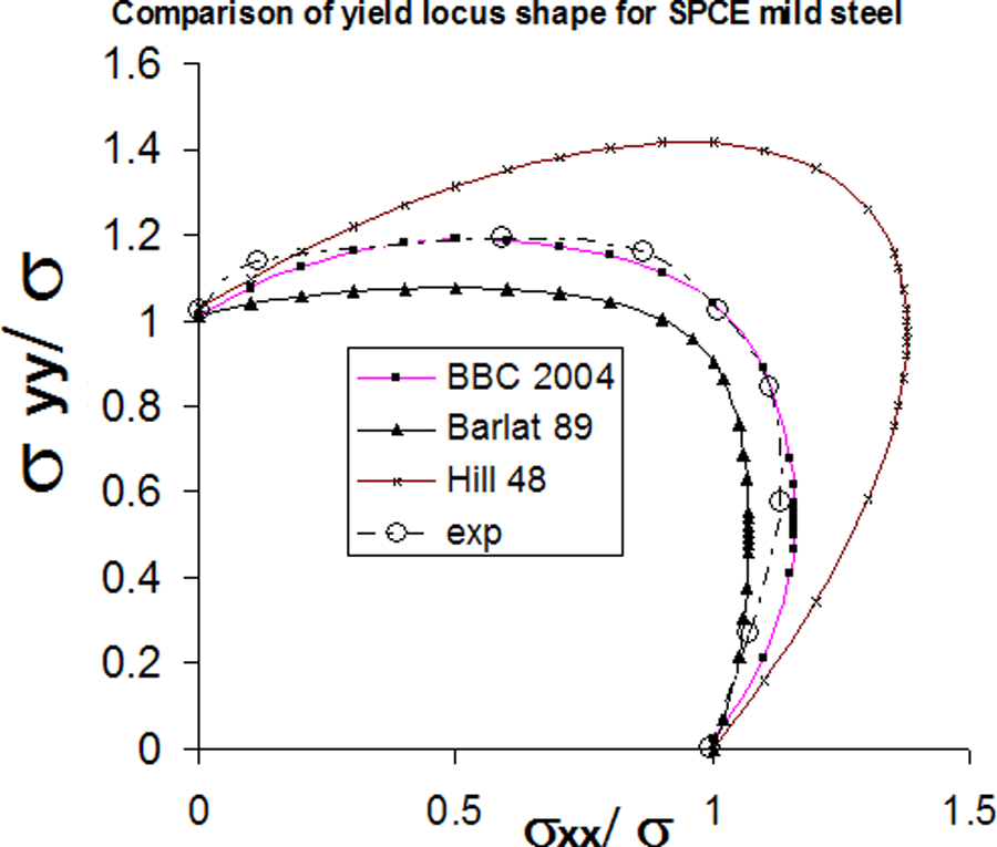
Comparison of yield loci predicted by different yield criteria for mild steel.
More recently, different approaches have been attempted to describe the yield behaviour. Aretz 29 generalized the Barlat 89 criterion using two additional material constants and used simple numerical methods to calculate the yield surface gradient. Tong 30 proposed a yield criterion for plane stress condition using a Fourier series to represent anisotropic material functions. Vegter and van den Boogaard 31 used an interpolation function to directly fit the experimental points determined along a yield locus. Over the last decade, several advanced yield criteria have been proposed with additional material coefficients to model anisotropy.9,32–34 Although most of the advanced yield criteria use the stress exponent based on crystallographic calculations, they are phenomenological in nature. This leads to a complex mathematical description demanding many experimental data points.
It is to be noted that most of the initial developments in anisotropic yield criteria were applicable for steel sheets. Development of yield criteria after the 1970s focused on aluminium alloys and in the recent years, attention has been towards hexagonal close packed (HCP) crystal structured metals like magnesium alloys, where the additional twinning effect introduces asymmetry of yield surface. 33 Thus, the choice of yield criterion is highly dependent on the material being modelled. 35 In addition to material, the experimental constants required to completely define a yield criterion plays a major role. An appropriate choice of yield criterion is essential for accurate prediction of yield locus with minimum experimental data.
Effect of friction in sheet metal forming
The interface between the sheet metal and tool surface influences the deformation behaviour and residual stress in a sheet metal component. The resistance to metal flow increases with friction coefficient causing premature failure. 36 The effect of restricted metal flow owing to friction is highly sensitive in the region of maximum deformation. 37 In the case of sheet metal forming analysis, the role of friction in deformation behaviour is complex and is dependent on the surface of sheet, die and lubricant. The friction coefficient varies with the deformation mode of the material and different tests are developed to understand the behaviour. 38 The influence of friction in metal forming has gained considerable interest and several studies have been carried out.39–43 By and large, it is understood that the influence of friction varies with location depending on its strain history; however, no acceptable model of friction, considering the strain history, is attempted so far. The friction effect is generally modelled using the Coulomb friction model with a constant friction coefficient.
Residual stress owing to sheet metal forming
The sheet metal component, upon unloading from the forming tools, attempts to release the stored elastic energy, which is termed spring back. Owing to its complex shape, sheet metal components undergo different levels of deformation and hardening at different locations. This restricts the complete release of stored elastic energy within the component, resulting in residual stresses. 44 Residual stresses, or locked-in stresses, could also be generated at microscopic level owing to incompatibility between the co-existing different phases of material and non uniform hardening within the same component.36,45
Residual stress distribution in a sheet metal component is usually complex as the deformation behaviour in the component differs at each location owing to geometry. 46 The residual stress (simulation and experiment) built in a simple hemispherical cup specimen along two directions is shown in Figure 4. The residual stress varies through the thickness of the component. Besides, the anisotropy in sheet metals explained above also influences the residual stress distribution. The variation of residual stress (tangential and axial components) with thickness and sheet direction in a section of a deep drawn cup is shown in Figure 5.

Residual stress in a simple hemispherical cup specimen: simulation and experiment. (a) Geometry of cup specimen indicating the directions of residual stress measurement; (b) residual stress along rolling direction; and (c) residual stress along transverse direction. The experimental results are based on the residual stress measurement using an x-ray diffraction technique. (Reprinted from Hariharan et al.46 with kind permission from Springer Science+Business Media.)
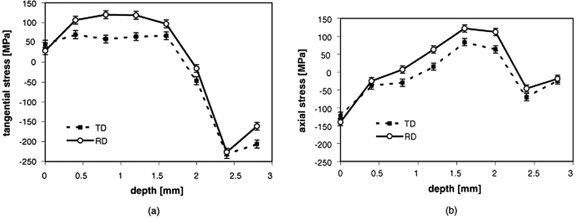
Variation of residual stress with thickness and direction in a deep drawn cup; RD-rolling direction, TD- transverse direction. (Reprinted from Gnaeupel-Herold et al., 47 with permission from Elsevier.)
Owing to the complex distribution of residual stresses in a sheet metal component, experimental measurement of residual stresses are limited.48,49 However, the residual stresses play an important role in the structural life of components. The longitudinal cracking commonly observed in austenetic stainless steel components is owing to the detrimental effect of residual stresses induced by the martensitic transformation during the forming process.36,50 This indicates that the material being formed and the process parameters play an important role on the residual stress distribution in a sheet metal component.51–53
Fatigue of sheet metal components
The majority of structural components are subjected to cyclic fatigue loadings. The residual stresses predicted in a formed component made of anisotropic sheet metal need to be integrated with fatigue analysis. However, material anisotropy, in addition to the residual stress, independently influences the fatigue behaviour. The effects of anisotropy and residual stress in fatigue life of sheet metals are discussed in the following sections.
Effect of sheet metal anisotropy in fatigue
Although the effect of mechanical properties and microstructure on the strain-life fatigue is widely studied, limited attempts have been made to understand the influence of anisotropy on the fatigue behaviour. 54 Hong et al. 55 investigated fatigue behaviour of a rolled Mg–3Al–1Zn alloy and observed the difference between fatigue behaviour in rolling and normal direction owing to twinning–detwinning characteristics of the HCP crystal structure. The influence of texture in fatigue behaviour in magnesium alloys was also investigated by Wu et al. 56 and Park et al. 57 Fatigue life along the normal direction was observed to be inferior when compared with fatigue behaviour along the rolling and transverse directions (Figure 6). 56 Poor fatigue life along the normal direction compared with rolling and transverse directions was observed in rolled 03KhI6N9M2 steel. 58 The deformable sulphur inclusions (MnS) in steel can induce anisotropic effects in hot rolled steel, which in turn results in poor fatigue properties along transverse directions.59,60
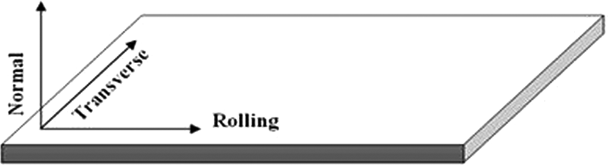
Schematic representation of rolling, transverse and normal directions in a rolled sheet.
Most of the work discussed above and other similar work concentrated primarily on the experimental investigation of anisotropy effect.61,62 Attempts to model anisotropic fatigue behaviour using constitutive plasticity equations are scarce, though not unavailable. 63 Lin and Nayeb-Hashemi 63 modelled the cyclic stress–strain behaviour of orthotropic Al–6061–T6 alloys using the Hill 48 anisotropic yield criterion, which was subsequently extended to predict the fatigue-life relation. 64 However, the fatigue constants used to correlate the directional properties are applicable only to the particular orientation and cannot be related to other orientations. 65 This results in experimental determination of constants from fatigue tests for every orientation of interest. Subsequent to the work of Lin and Nayeb-Hashemi, 63 efforts on modelling anisotropic behaviour in fatigue are scarce.
A new strain-life model incorporating the effects of anisotropy in fatigue-life calculation, free from the limitations of prior work is needed.
Effect of residual stress in fatigue
The residual stress induced in a sheet metal component alters the mechanical behaviour. The residual stress effect in fatigue can be considered as an equivalent mean stress–strain. In general, tensile pre-strain improves the life in a high cycle region and has an adverse effect in a low cycle region, as shown in Figure 7. The influence of pre-strain is dependent mainly on the material under study. Dual phase steels exhibit negligible influence on fatigue behaviour at pre-strains less than 8%,67,68 whereas significant influence is observed at pre-strains greater than 10%.69–70 Similar behaviour is observed in other high-strength steels like high strength low alloy (HSLA) steels67,71 and transformation induced plasticity (TRIP) steels. 72 Phase transformation during pre-straining has an additional influence in the case of multi-phase materials like dual phase (DP) steels, stainless steel and TRIP steels.71,72 For constant phase materials like low carbon steels, pre-straining leads to fatigue life improvement in the high cycle region and vice versa in low cycle region. 73 Thus it is observed that the effect of pre-strain on fatigue life varies with the material under study.
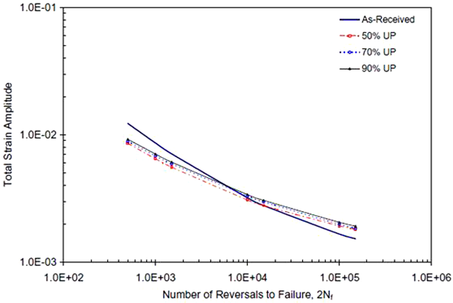
Influence of pre-strain (50% to 90%) on the strain-life fatigue behaviour of a dual phase steel. (Reprinted from Le et al., 66 with permission from Elsevier.)
The manufacturing process variables and heat treatment have considerable influence on the fatigue behaviour under pre-strain. 74 Laser formed HSLA steels exhibited superior fatigue behaviour owing to surface hardening by laser irradiation. 71 Similarly, Nikitin and Besel 75 observed that surface treatment of AISI 304 and SAE 1045 steels by prior rolling enhanced the constant stress amplitude fatigue behaviour in increasing order when compared with untreated conditions.
In addition to the above, the strain path and anisotropy in sheet metals play an important role in the fatigue life of materials.66,73 The fatigue life along the transverse direction is observed to be higher than that of the longitudinal direction in high cycle fatigue, however, negligible difference was noticed in low cycle fatigue owing to cyclic softening. 73 Improvement of fatigue life in the high cycle region and detrimental effect in the low cycle region was noticed in all strain paths. 73 However, this is in contrast to the observation of Le et al., 66 where fatigue life in plane strain mode improved in both the low cycle and high cycle fatigue region. The discrepancy could be owing to the difference in material and pre-strain levels used in the study.
It is inferred from the above discussion that the influence of pre-strain on fatigue life is dependent on the level of pre-strain, material, microstructure, load type, strain path and geometry. Heinilä et al. 76 reported the adverse effect of through thickness residual stresses induced by cold forming on the fatigue failures of rectangular hollow cross section steel tubes. The fatigue behaviour is highly sensitive to the level of prior cold working; a 25% cold rolled AISI 301 steel exhibited stress relaxation under bending fatigue load, whereas an increase in stress amplitude was observed in 50% cold rolled condition. 77 This indicates a complex interaction of prior cold working and fatigue. By mapping the results from sheet metal forming to further structural analysis, attempts have been made to predict fatigue behaviour, including forming effects.78–80 Wang et al. 80 included residual stress and thickness distribution of an engine bracket owing to forming in the fatigue analysis. The fatigue life and location of failure changed when forming effects were taken into consideration.
The need to integrate sheet metal forming effect on fatigue life
Though modelling of sheet metal forming has witnessed active research in the past decade, forming simulation has been primarily used in the die making industry. Consideration of residual stresses predicted in forming for further structural analysis like fatigue is limited. 80 However, assembly and residual stresses, which are generally present in pressed-panel assemblies, play a significant role in the life of a structure and need to be accounted for. 81
Controlled fatigue tests with induced pre-stress in sheet metal samples indicate that residual stress influences the life of a component. Traditional sheet metal component design for automobile does not account for the prior residual stresses. A suitable factor of safety is adopted to account for the fatigue in design. In general, the structural finite element analyses of automobile components use isotropic material models assuming homogeneous material properties and zero residual stresses. 82
The material anisotropy, in addition to the residual stress distribution, influences the fatigue behaviour of materials. The influence of sample orientation on the fatigue life has been widely reported. As shown in Figure 8, the pre-strain and residual stress for similar external loads varies with specimen orientation owing to anisotropy. Similarly, for a similar cyclic strain amplitude, fatigue behaviour of material varies with orientation. The variation of residual stress owing to anisotropy and its complex interaction with the anisotropic fatigue behaviour should be accounted for while estimating fatigue life of sheet metal components. Lack of appropriate constitutive models to account anisotropic effect on fatigue and a methodology to incorporate the forming-induced residual stress in fatigue analysis, limits the realistic estimation of fatigue life in sheet metal components.
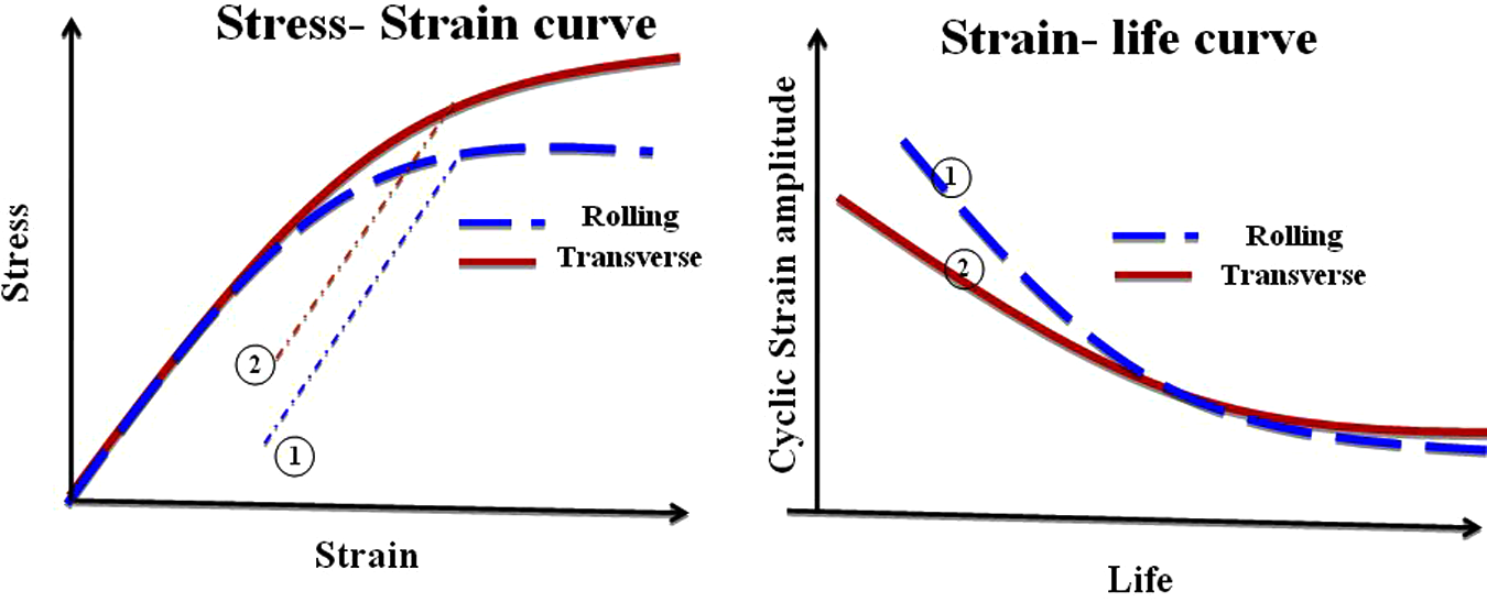
Schematic representation of a complex interaction of material anisotropy in residual stress and fatigue. (a) Monotonic tensile behaviour indicating different pre-strain on unloading. (b) Directional behaviour of fatigue.
Thus, the manufacturing process is modelled by tool makers who are less concerned with residual stresses, and fatigue analysis is carried out by component designers who ignore the prior residual stress in the component owing to the manufacturing process. The ideal flow of modelling and the present practice is represented in Figure 9.
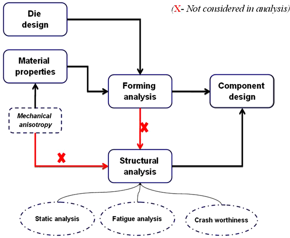
Flow chart describing the ideal and present scenario of utilizing sheet metal forming analysis
Finite element modelling of forming and fatigue
The finite element method is an useful technique to understand the material behaviour and residual stress induced during complex large deformation plasticity problems like sheet metal forming.83,84 Though the underlying fundamental plasticity relations were developed as early as the mid-twentieth century, finite element modelling of the sheet metal forming process using plasticity relations began after the 1970s. 85 The initial work on large deformation plasticity began as an extension of conventional finite element methods. 86 Historical development in the area of modelling sheet metal forming is discussed in Kobayashi et al. 86 , Makinouchi et al. 87 and Tisza. 88 It is generally agreed that, for large deformation and high strain rate problems like sheet metal forming, an explicit method is more suitable than an implicit method.89,90 On the contrary, for predicting spring back after forming, an implicit method, which is effective for quasi-static problems, is used. 91 However, convergence issues are faced while using an implicit method for spring-back. 92
The deforming blank is generally modelled using two-dimensional (2D) quadrilateral shell elements, though attempts on using three-dimensional (3D) elements have also been made. 93 While using shell elements for sheet metal forming, the variation of stress–strain behaviour through the thickness owing to bending is captured using integration points along the thickness direction. The solution accuracy of the metal forming analysis is improved by using an adaptive mesh refinement technique, where the initial coarse mesh automatically subdivides into finer elements based on effectiveness of the strain or stress gradient. 92
The forming tools, through which the forming force is transferred to the deforming material, are treated as rigid. The contact and sliding boundary condition between tools and blank are complex and non-linear. The contact algorithm should ensure that nodes on the sheet should not penetrate or adhere on the tool mesh. Some of the commonly used contact algorithms are discussed by Wagoner and Chenot. 94 The Coloumb friction model, with constant friction coefficient, is used for sheet metal forming applications.3,89
Material models in sheet metal forming
The accuracy of forming a prediction mainly depends on the choice of material model. The material model for plastic deformation analysis consists of a yield criterion to describe initiation of yield, a flow rule to relate the stress and strain state and a hardening rule to describe the subsequent yield behaviour. In the case of sheet metal forming, yield behaviour and corresponding flow rules can be modelled by any of the yield criteria discussed in the previous sections. Limited literature is available on the influence of yield criteria on the prediction of forming strains in a component.95–97 Wang and Lee 97 investigated the strain distribution in a spherical dome shape and inferred that strain distribution predicted by Hill 48 and Hill 90 are similar. Mattiasson and Sigvant 96 investigated the results of hemispherical cup forming experiments with Hill 48, Barlat 89 and BBC 2000 criteria and inferred that forming strains are less sensitive to the choice of yield criteria. It is interesting to note that, unlike limiting strains, forming strains are less sensitive to the choice of yield criteria.95,96 It is inferred from the available literature that the influence of yield criteria is dependent on the strain modes; a plane strain mode seem to be more sensitive to choice of yield criteria than other strain modes. 98
The hardening behaviour to model subsequent yield behaviour can be isotropic, kinematic or a combination of both. In most of the sheet metal forming simulations, isotropic hardening is used, where the yield locus expands uniformly with plastic strain. Since forming process modelling involves monotonic loading without any intermittent load reversal, assuming isotropic hardening behaviour does not affect the accuracy of the prediction significantly. 99 Hill 48 yield criterion with isotropic hardening is commonly used for modelling the sheet metal forming process. 100 The finite element results of an automotive bumper simulated assuming Hill 48 yield criterion and isotropic hardening is compared with the experimental results in Figure 10. The major strain at the end of forming is compared between simulation and experiment. However, the isotropic hardening is not suitable for modelling subsequent forming stages and spring back, which involves reversal of load path. 99
Comparison of simulation results (major strain) of an automotive bumper with experiment. (Reprinted from VanHoek 101 with permission.)
Simulation of spring back
The sheet metal component undergoes spring back after forming. Accurate modelling of spring back is a much debated topic. Accuracy of spring back prediction depends upon the stress state at the end forming, appropriate hardening rules to account for the stress reversal and choice of element formulation. 102 As discussed in the previous section, isotropic hardening is not sufficient to describe the spring back behaviour. 103 Alternately, a mixed isotropic–kinematic hardening rule is needed for accurate prediction of spring back. 104 The spring back process is essentially a single stage stress relaxation. Therefore, accuracy of the final stress state of the formed component decides the accuracy of the spring back prediction. However, most of the validation for the sheet metal forming process compares the surface strain and thickness distribution and not the final stress state.
Thus, choice of material model for sheet metal forming simulation, based on experimental validation of surface strains, need not necessarily guarantee an accurate spring back prediction. Mattiasson and Sigvant 96 observed that Hill 48 and Barlat 89 criteria predicted similar strain distribution, however the peak load, which can be related to the stress state at the end of forming, had considerable difference between the two criteria.
Fatigue simulation of sheet metal components
The advances in modelling of the sheet metal forming process are utilized extensively by the tool making industry, as simulation substantially reduces the development time and tryouts for die making. 102 However, relating the predicted residual stresses to durability of formed components is not practised in general; as a consequence, life of components is affected.
The residual stresses retained in the component influences the fatigue behaviour of components. Since most of the forming simulations use adaptive meshing, the forming results should be mapped to suitable mesh for structural fatigue analysis. 105 The presently available mapping algorithm has several restrictions; only one stress or strain component can be mapped,106,107 whereas six stress components and six strain components are needed to describe the complete stress–strain state of the component. A mapping algorithm for complete mapping of stress and strain components is still under research.
The residual stresses obtained should be integrated with the fatigue modelling for realistic life prediction of components. Let us consider a smooth specimen subjected to constant amplitude load cycle. During high cycle fatigue, though the net section stresses are elastic, localized plastic deformation occurs in the grains that are not favourably oriented to the loading direction. This is further amplified by microscopic stress raisers like inclusions and inhomogeneous microstructure. During low cycle fatigue, as the specimen is subjected to cyclic loads, the material cyclically hardens or softens depending on the prior straining history and mechanical properties of the material. 108 The fatigue behaviour is further complicated with the presence of mean stress or mean strain, where ratcheting or cyclic relaxation occurs. 109 The fatigue behaviour is highly dependent on the surface finish, microscopic structure, size, heat treatment and other prior processing effects. 110 Constitutive modelling of the complex material behaviour during fatigue is difficult and empirical relations have been developed to equate the cyclic stress or strain to the life of the smooth specimens. 111 Owing to the complex interaction of several variables, such experimentally determined empirical relations are highly statistical in nature. 112 The effect of mean stresses and other variations, like surface finish, can be accounted for by suitable correction factors. 108 Unlike mean stress, the residual stresses owing to forming are not uniform and vary with location, which leads to complex interaction of fatigue behaviour between locations. The above discussions on fatigue modelling are further complicated when the component is subjected to a multiaxial state of stress. Besides, most of the components are not smooth as tested in laboratory conditions. The component geometry results in stress concentrations of specific zones, which results in non-homogeneous fatigue behaviour.
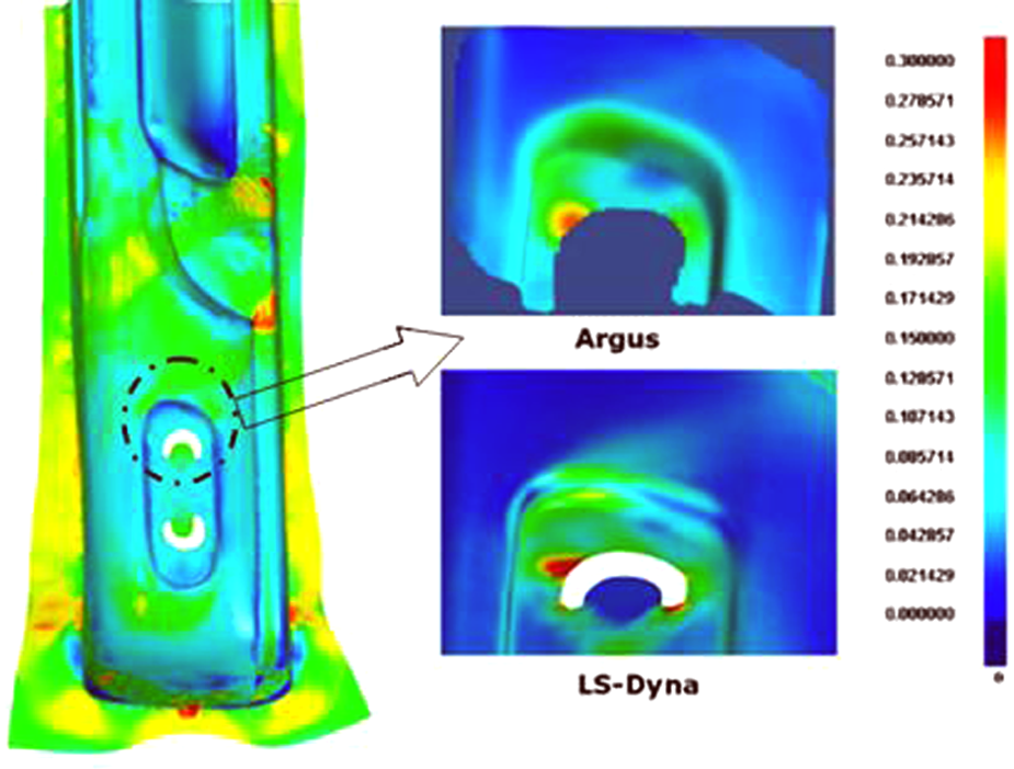
Thus, finite element modelling of cyclic loading, considering the localized damage in each repeating cycle, is difficult owing to the complex material behaviour. In the present scenario, static analysis of one half cycle of the component is performed and the stress amplitude obtained is correlated with the stress life or strain life relations obtained experimentally. Commercial packages like MSC.Fatigue, FEMFAT and fe-safe are available, where the stress states of component can be correlated with the experimental empirical relations. This approach may be suitable for high cycle fatigue. However, when plastic deformations occur in each cycle, the cyclic hardening or softening cannot be accommodated by this approach. Figure 11 shows the fatigue analysis of a tubular automotive engine bracket. 80 The thinning of the tube owing to forming is accounted in the fatigue analysis and it is observed that the failure location and fatigue life changed when the forming effects are incorporated. However, as discussed, the complete stress and strain state of the component is not included in the fatigue analysis.

Fatigue analysis incorporating thinning owing to forming in an automotive engine bracket. (a) Results of fatigue analysis without thinning effect. (b) Results incorporating thinning due to forming. (Reprinted from Wang et al., 80 with permission from Elsevier).
In the finite element simulation, though it has witnessed advancements in predicting the deformation behaviour during forming, incorporation of residual stress owing to forming in the subsequent fatigue analysis is very poor. The challenges in integrating the forming results in fatigue life prediction are summarized in the next section.
Challenges in integrating the forming results in life prediction
Despite the advancement in modelling of sheet metal forming, the residual stress induced during cold forming is generally not considered in design. Some of the challenges involved in accounting for the forming effects are discussed below.
As discussed, the major application of sheet metal forming simulation is for the tooling industry113,114 and as a result, formability of the component rather than the functionality of the component has gained primary importance. 82
Material models are generally validated with surface strain in the component.115–117 The spring back phenomena involves stress release post-forming and is preferable to correlate the final stress state; however the final shape of the component after spring back is used to validate the spring back behaviour. 102 Ideally, residual stress should be used to validate the material models for sheet metal forming and spring back. 74
Typical sheet metal components undergo a multi-stage deformation process, forming, trimming and flanging. The sheet metal components are subjected to different strain paths during multistage deformation. 118 However, the present methodologies of strain-based evaluation are highly sensitive to strain path 119 and hence it is difficult to determine the final stress state of the component. This is aided by the difficulties in the measurement of residual stress as there is no method that is independent of the residual strain. 120
In addition to the above, the sheet metal component undergoes stress reversals between forming stages in multi-stage forming and during spring back. Such stress reversals cannot be modelled using conventional isotropic hardening. 121 Mixed hardening models, to account for stress reversals, are under research.122,123
Adaptive meshing is employed in large deformation problems like metal forming. The forming simulations with adaptive mesh result in poor mesh quality (Figure 12). Robust mapping algorithms are essential to map the forming results to further structural analysis, which are still under research. 105 A commercially available mapping algorithm from Altair – Hyperworks software – can map only one component of stress or strain, whereas all six components of stress and strain tensors are required for further structural analysis.
The commercially available software for fatigue analysis, like MSC-Fatigue, fe-safe, ANSYS-Fatigue module and FEMFAT code, superimposes the stress results of finite element analysis and calculate the life by extrapolation. This approach is not suitable for the high strain range where plastic deformation occurs during cyclic loading.
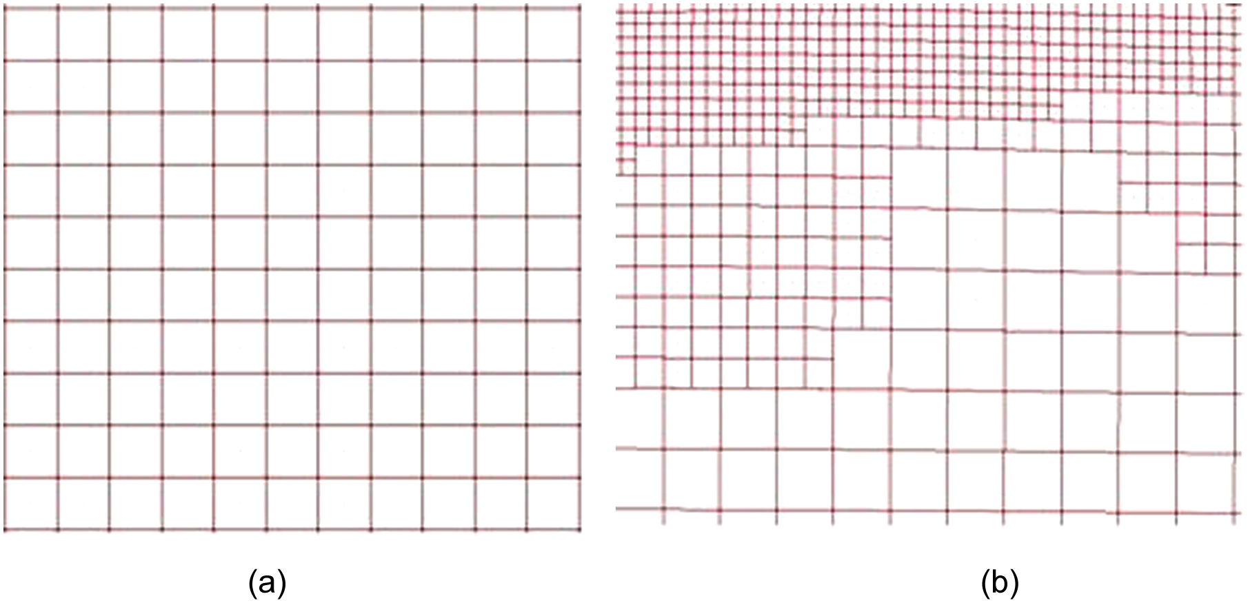
Adaptive meshing: (a) coarse initial mesh, (b) adaptive mesh with subdivided elements.
Conclusion
From the survey of available literature, it is inferred that, though the finite element modelling of sheet metal forming processes have witnessed rapid development in the past decade, the focus has been primarily on the formability and not functionality. The mixed hardening models to describe the multistage forming and spring should be concentrated to ensure the accuracy of the final stress state prediction in the component. The validation of sheet metal is based on surface strains and not on the residual stresses imparted, which imposes the difficulty in choosing appropriate material models for the accurate prediction of residual stresses. The lack of established stress-based formability models and mixed hardening laws, coupled with the experimental difficulties in direct measurement of residual stress, limits the application of forming results in further structural analysis.
The material anisotropy independently influences the residual stress distribution and fatigue behaviour, and hence, accounting for material anisotropy in fatigue modelling is critical. However, most of the fatigue models for uniaxial and multiaxial fatigue criteria are valid for isotropic materials only. Suitable modification of the existing criteria or development of new criteria incorporating the material anisotropy is essential.
Limited work has been done on the fatigue life estimation of sheet metal components accounting for the initial anisotropy and residual stresses. The importance of residual stress in the fatigue life of sheet metal components is understood from simple tensile specimens. Fatigue analysis of sheet metal components with a complex residual stress distribution is experimentally challenging. The commercially available software for fatigue analysis extrapolates the half-cycle stresses in the fatigue life curves. An intensive finite element model that computes the cycle-by-cycle deformation with localized plasticity is necessary for accurate fatigue simulation. The present material models used for metal forming may not be sufficient to model the cycle-by-cycle deformation behaviour and new constitutive equations to accommodate the cyclic hardening and softening needs to be developed for appropriate numerical modelling.
Footnotes
This research received no specific grant from any funding agency in the public, commercial, or not-for-profit sectors.