
Abstract
To achieve efficient, fast and cost effective production, designers must consider all the manufacturing stages a product has to go through. A case study in a manufacturing setup shows that owing to the differences in perception of an engineering component, the coordination between design and manufacturing becomes difficult. Semantic interoperability problems are therefore faced when knowledge sharing for the purpose of manufacturability verification is attempted through computer-based knowledge bases. Ontologies have a reputation for solving semantic interoperability problems. Combined with shape feature-based models of components, ontologies provide a basis for seamless knowledge sharing. This article demonstrates the use of ontologies for analyzing the manufacturability of engineering components in the early design stages. This is done by developing shape feature-based ontological models of these components and associating manufacturability knowledge with these models. To achieve this, an ontological modelling technique is proposed that uses shape feature-based geometrical models of engineering components as building blocks. The knowledge associated with these models to demonstrate their use for manufacturability verification is derived from the findings of a case study also detailed in this article.
Introduction
Ever soaring competition has made it difficult for manufacturing companies to survive. Manufacturers now try their best to cut costs and production times wherever possible and product design plays a very crucial role in achieving this. A simple and intelligent design means reduced time to market and lower manufacturing costs. The most optimal and intelligent design is one that is suitable for all of the stages of manufacturing, assembly, repair, use and disposal. Product lifecycle stages are, therefore, an important consideration during the design of a product. These stages can be catered for through concurrent engineering where a design is finalized after negotiation with all the stakeholders. However, in a busy manufacturing environment bringing everyone to the table can be difficult, time consuming and, therefore, costly. Computerized knowledge-based systems can be helpful to reduce time wastage. They save time and money by automating the process of concurrent engineering. This involves modelling a product in a computerized knowledge base, associating manufacturing, assembly, repair, use and disposal knowledge with the model and then using this knowledge to help the designer produce a suitable design. There have been several methodologies for the development of computerized product models. Among these methodologies, it is generally agreed that shape feature-based modelling is the most useful for carrying out production planning or computer-based concurrent engineering tasks.1-4 However, a case study in a manufacturing enterprise reveals that the interpretation of shape features in a component may not be the same across different departments. This gives rise to the problem of semantic and syntactic mismatches in product models developed independently in these departments. These mismatches, in turn, hinder knowledge sharing during the process of computer-based concurrent engineering. This problem can be relieved through the use of ontological knowledge bases. This is because ontologies have been proven useful to enhance the semantic and syntactic interoperability.5,6 This article, for this reason, proposes a methodology for building shape feature-based ontological product models. The benefits of these models are twofold. First, being constructed through shape features, they provide an efficient means of attaching manufacturability knowledge with them. And second, being in the form of ontologies, they make it easier to maintain the semantic and syntactic interoperability across the knowledge bases existing in different domains. It should be noted that within the broad area of concurrent engineering, this article focuses only on manufacturability analysis and verification.
This article has three key contributions. Through a case study, it first highlights the contemporary industrial needs for an interoperable knowledge-sharing system to automate the process of manufacturability verification. Second, it proposes a methodology to develop shape feature-based ontological product models of engineering components with the focus on manufacturability analysis. And third, it demonstrates the use of an ontological formalism called Common Logic to formalize and use these models for manufacturability verification.
The article is organized as follows. The industrial case study is presented first, which enlists the requirements for a manufacturability analysis and knowledge sharing system. A brief literature review is then presented to identify the shortcomings of the available methods to fulfil these industrial needs. The proposed modelling methodology is explained next including the Common Logic-based formalization of the ontological model of a component studied during the case study. Next comes the explanation of the way these ontological models are used to analyze manufacturability. Conclusions and further research are presented at the end.
The case study
This section presents the details of a case study conducted in an aerospace compressor disc manufacturing plant. The presented findings of this case study highlight the need of an ontology-based knowledge-sharing system for manufacturability analysis. These highlighted requirements are, afterwards, used to prove the usefulness of the proposed methodology. Through the analysis of a selected component, some lapses in the interdepartmental communication needs were identified when employing shape feature-based design and manufacturing. Two departments studied were design and production. The primary sources of data were individual one-to-one interviews, but the company intranet and archival information also contributed to this case study. Figure 1 illustrates the selected component. For proprietary reasons, the exact form of the studied disc is not shown here, but the illustrated hypothetical shape completely fulfils the essential requirements to elaborate the case study findings.
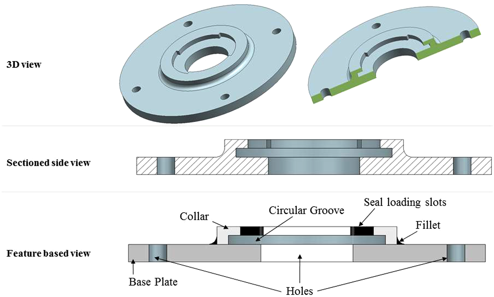
A hypothetical component.
Shape feature interpretation differences
During the case study, the studied component was analysed from the perspective of the shape features it contained. It was found that different parties involved in the knowledge sharing process have different perceptions of an engineering component and its features. Designers, for example, designated features in a component according to the function they perform. Manufacturers, on the other hand, preferred the criteria of manufacturing and inspection methods used to produce a certain part of a component. A look at the production route of the studied disc revealed that it mainly required the processes of turning, drilling and milling for its production. An important thing to note here is that the demarcation made between design features to make them distinct does not work when manufacturing features are to be identified. This is because more than one design feature can be produced during a single manufacturing process.
Therefore, a manufacturing feature may possibly be a combination of several design features. An obvious designation of manufacturing features is, therefore, turning features, milling features and drilling features as categorized below. For the disc studied here, the design and manufacturing features were divided as shown in Table 1. The illustration shown in Figure 2 indicates how more than one design feature combines to form a single manufacturing feature. For example, base feature and stress relieving features form the turning feature.
Design and manufacturing features.
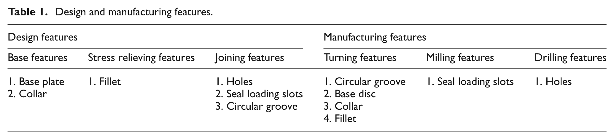
Design and manufacturing features.
Perceived interoperability issues
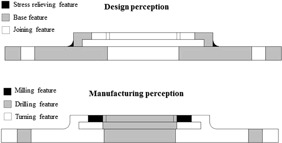
It has so far been established that the interpretation of different parts of the same component may differ in design and manufacturing domains. An example of this difference is illustrated in Figure 3. In addition, for a manufacturer, the terms joining feature or stress relieving feature may not make any sense and the same features, or a combination of them, may be identified as drilling features and turning features. This is a typical example of perceptual differences that may lead to conceptual mismatches when knowledge is modelled independently in two domains. But this is not all that may go wrong and during the case study some terminological differences were also found to exist. For example, the portion of disc between holes and the collar is called a web by the manufacturing engineers, while it was designated as a diaphragm by the design people. Similarly, the middle extended portion of the disc is called a cob by the design engineers while it is named as a collar by the manufacturing people on the shopfloor.
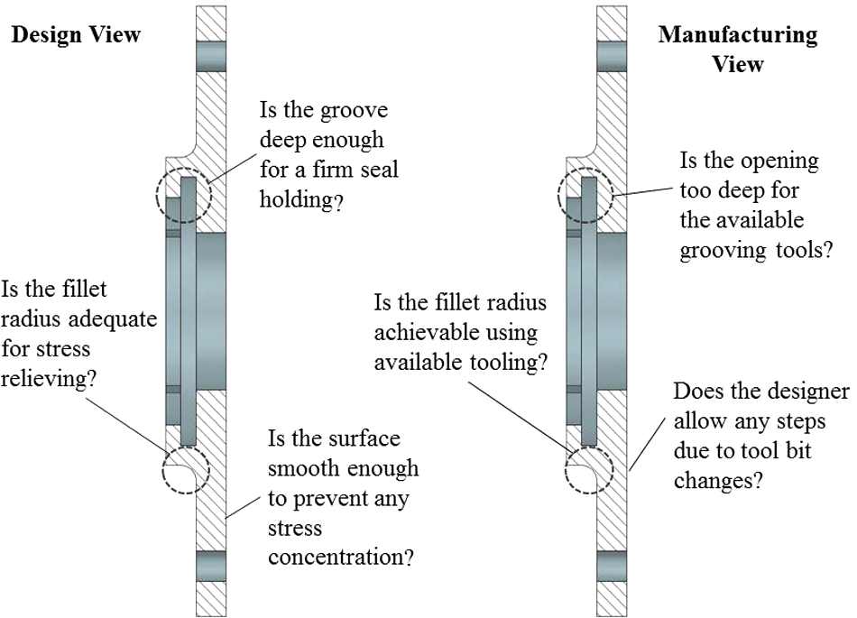
Comparison of designer’s and manufacturer’s views.
One may argue that these perceptual differences do not matter as separate geometrical features are clearly identifiable in a component, whether they are looked at by the designer or the manufacturer. This objection stays valid as long as only the geometry of a component is the focus of attention. However, as soon as it comes to the manufacturing methods, these perceptual differences suddenly become very important because in a single manufacturing operation more than one geometrical feature is obtained, as is evident from Figure 2. Another way of looking at this problem is from the feature-dependability point of view. In the design domain, the feature dependability is different from the dependability of different geometrical parts of a component when machined as a single unit. In this scenario, in a computerized knowledge base, when manufacturing knowledge is associated with a component the distinction of features from the design point of view becomes meaningless. It is here that one realizes the importance of perceptual differences between the two domains. Furthermore, things become more complicated when this knowledge is to be fed back to the designer. This is because the designers need to receive feedback in the form of separate and distinct design features and not as a collection of features tagged with the name of some manufacturing operation that may be meaningless to them.
Owing to all these differences in understanding of the two domains, some semantic and syntactic variations are bound to occur when the same component is modelled in two independently developed knowledge bases. A standard set of features may not be very helpful as it can never be made suitable to both design and manufacturing. The modelling scheme, therefore, needs to be in a form that can easily be modified according to the needs of a certain domain, but is still interoperable enough to prevent any misinterpretation during knowledge sharing. For that reason, the modelling approach presented in this article uses ontologies, along with shape features, to model components. This is because ontologies are regarded as helpful in maintaining interoperability across diverse domains. More explanation of ontologies and shape features is given in the next section.
Ontologies and shape features for manufacturability analysis
This section briefly reviews ontologies, product shape features and some existing relevant research work for manufacturability analysis.
Ontologies
Defined as a formal and explicit specification of a conceptualization, 7 ontologies are regarded as being useful to enhance interoperability. Simply defined, an ontology is a hierarchical arrangement of concepts and their relations, together with the constraints on those objects and relations.8,9 The way ontologies define knowledge makes it processable by machines and understandable by humans. 8 They provide a basis for shared meaning. 10 Ontologies not only provide a way to preserve knowledge, but they also enable one to produce pre-packaged sets of information and knowledge and make them available for individual use, or for constructing large knowledge sets by using them as building blocks. 11
When these building blocks, or pre-packaged sets, of information and knowledge take the form of product shape features, a feature-based ontological product model can be produced. Shape features are discussed next.
Product shape features
Product shape features are found to be very useful to encapsulate engineering intent into computer systems. 4 Currently, one of the main problems in the implementation of computer-based concurrent engineering is the development of methodologies and software tools to link the manufacturability information and knowledge with product models. 3 Shape features are useful in holding this information. 2 In feature-based design, the manufacturability of a component is largely determined through the geometric interactions between features. In this approach, the designer creates a component by choosing pre-designed but geometrically modifiable shape features. These features are then put together to form the whole component. 2 However, features alone are not sufficient to completely model a part. Some relations existing between features and constraints governing the use of these features also need to be defined. 1 As will be shown, ontologies provide a good infrastructure to build these relationships and constraints.
Shape features and ontologies have been used in the field of manufacturing. To explore this further, a brief literature review is presented in the next section.
Existing work
Existing work in this field is reviewed here with the aim of recognizing the use of both ontologies and shape features for manufacturability analysis. Industry is increasingly aware of the need to cater simultaneously for a host of requirements, such as manufacturability, resulting in a series of design for X (DFX) analyses. 12 However, most of the time either an ontology or shape features are used for this purpose. In only a very few cases were both of these concepts put together to propose a solution for manufacturability analysis. For example, Yoo and Suh 13 propose a computerized concurrent engineering system consisting of three main parts.
An integrated product information model (IPIM) using the standard for product model data, STEP standard. 14
A hierarchical database to store these models.
An integrity constraint validation mechanism based on EXPRESS, 14 which is a formal information modelling language from STEP.
Although the use of a hierarchical database, along with an integrity constraint validation mechanism, indicates an ontology-like structure, the work does not give a detailed method to build ontological models using STEP. In another work, Li et al. 15 propose a neural network-based feature overlap detection methodology. The technique uses shape features to develop component models, but there is no use of ontologies to contain these features for an interoperable knowledge-sharing system. Jacquel and Salmon, 2 in another work, have developed an approach for manufacturability verification and conflict attenuation. This approach applies software agent technology to feature level in a shape feature-based computer-aided design (CAD) system. The relevant part of this approach is the use of shape features to design components. No consideration, however, can be found for semantic interoperability among diverse and dispersed knowledge sources during manufacturability verification through knowledge sharing. Another example is the work of Matsokis and Kiritsis. 16 They converted a semantic object model (SOM) into an ontology for better sharing and exchange of product-lifecycle knowledge. SOM is a product-item oriented model capable of storing data of the product’s lifecycle. The rationale they give for converting this model into an ontology is the reasoning capability of this technology, along with its data structure layout. There is, however, no consideration of the cases where shape features are used to carry manufacturing information and knowledge. In another work, Dutra et al. 17 propose an ontology-based architecture for collaborative design. This synchronous agent-based architecture helps in conflict attenuation during the early stages of a collaborative design process. Again, there is no use of shape features for product modelling. In all of these examples, either the ontologies or shape features are used.
Work that uses both features and ontologies includes the research of Jeng and Gill 18 who developed a CAD-based framework to design fixtures for machining of components. They use a knowledge base to aid the overall fixture design. This knowledge base consists of a feature-based database for work piece representation, a rule base for reasoning during the fixture design and a modular fixture database for use in fixture component selection. The use of a rule base and a shape feature-based database is similar to the work presented in this article. However, the approach of Jeng and Gill 18 does not address the semantic interoperability problem that may arise when features and rules are developed independently in different domains. In another work, Ma et al. 4 address the product feature-level interoperability issues and develop a collaborative product development system. Their use of an ontology, however, is at the meta level and the interoperability is attempted between different CAD applications rather than different domains. In another similar work, Abdul-Ghafour et al. 19 propose an ontology-based approach to explicitly specify, capture, interpret and reuse the product semantics. This is done for facilitating heterogeneous information sharing across CAD systems. Their approach features a shared ontology consisting of concepts of commonly used shape features. This is, however, just a high level conceptual approach and does not demonstrate the construction of ontological shape feature models.
The work presented in this article differs in a number of ways from the existing work reviewed here. First, the presented work combines the use of ontologies and shape features to model a component on a very fine granularity level. Second, since an ontology is used, the proposed modelling method paves the way to resolve differences in design and manufacturing perceptions during knowledge sharing. Third, no work in the extant literature can be found that uses Common Logic to developed ontological models of engineering components using shape features. As will be explained, Common Logic has some obvious benefits in comparison to other ontological formalisms. Therefore, this work is a unique contribution to the field of manufacturability analysis using ontologies and shape features.
The following text details the proposed modelling methodology.
Proposed methodology
The feature-based design process takes place by aggregating shape features into the form of one single component. During this process, manufacturability analysis, through shape features, is achieved by making the inclusion or modification of a form feature in a product conditional to the in-house manufacturing capabilities. These conditions can be created through ontological integrity constraints that monitor the feature incorporation or modification in the product model developed by the designer. A feature size or placement that conflicts with the stored knowledge in the form of integrity constraints is identified automatically. The following text explains how this is made possible.
Feature-based product models
There are three subsections in this section. First, a general geometrical description of a feature-based product model is provided. The second subsection explains how such a model is built as an ontology. In the third subsection, a formal or computerized version of this ontology is presented.
A geometrical feature model
A complete definition of a three-dimensional (3D) object and its orientation in space is a topic that belongs to a vast area of research and a review of all available dimensioning and positioning techniques is not the intention of this article. The aim here, rather, is to show how an existing method of 3D object dimensioning and positioning can be translated into the form of an ontology for manufacturability knowledge association and sharing. Two types of parameters are described here.
Dimensional parameters. A shape feature as a separate entity is defined through its dimensional parameters. These include the width, height, diameter, etc., and any other dimension that is needed for its complete definition. Figure 4 shows a hypothetical feature with A, B and Φ being its dimensional parameters.
Positional parameters. Shape features, when integrated to form product models, also need a complete description of their orientation in the 3D space. The second important characteristic is their positional parameters. These parameters include a reference point existing within the geometrical boundaries of a feature and a reference line passing through the reference point. The reference point requires its positional x, y and z coordinates, while the reference line is defined through its angles with x, y and z axes. In Figure 4, the abbreviations RP and RL represent the reference point and reference line of the hypothetical feature, respectively.
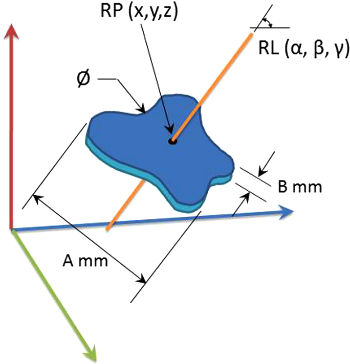
Feature orientation and placement.
These positional and dimensional parameters are included as essential characteristics of shape features defined as concepts in the ontology used to build the knowledge base. Figure 5 illustrates the component as an aggregation of its individual pre-defined shape features. Also shown in the figure is the ontology containing all the necessary concepts to build an ontological shape feature model of the illustrated component.

Component with features and its ontology.
An ontological feature model
Gruber 7 defines an ontology as a 5-tuple O = <CD, RD, FD, ID, AD>. Where CD is a set of class definitions, RD is a set of relation definitions, FD is a set of function definitions, ID is a set of instance definitions and AD is a set of axiom definitions. 19 These axioms are called theories by Gruber. 7 Following this definition, a feature model described in the previous section can be divided in components as follows.
Class definitions
These definitions include the component concept, the shape feature concepts, their dimensional and positional characteristics concepts and measuring unit concepts.
Relation definitions
These definitions are used here to describe, first, the relations between shape feature and the component, and second, relations between the feature characteristics and measuring units.
Function definitions
Functions are used here to define measuring units for the dimensional and positional parameters.
Instance definitions
The instances here are actually the parameterized models of individual features and of the component being their aggregated form. These instances are subsumed under the main ontology.
Axiom definitions
Axioms, rules, or integrity constraints are used here for defining a feature through its characteristics. Two main characteristics here are the dimensional and positional parameters. These rules are also used to model the manufacturability limitations. These rules caution the designer if the available features are used in such a setting that does not fulfill the manufacturability condition defined in the form of an axiom or rule.
Figure 5 shows how shape features and their characteristics, in the form of classes, are hierarchically organized to form the basis of an ontology. Figure 6 shows how an instance of the feature ‘basePlate’ and its dimensional and positional parameters are defined. In the same way, other features can be defined by their dimensional and positional parameters. This instantiation is further clarified in Tables 2 and 3. Axiom definitions are needed to make sure that none of the parameters for a feature are left undefined by the knowledge-base builders. For example, in this case the following three axioms have to be written:
For a complete definition of a basePlate, all five characteristics, i.e. its diameter, surfaceProfile, height, referencePoint and referenceLine, have to be defined.
For a complete definition of a referencePoint, all three coordinates (x, y and z) have to be defined.
For a complete definition of a referenceLine, all three angles (x, y and z) have to be defined.
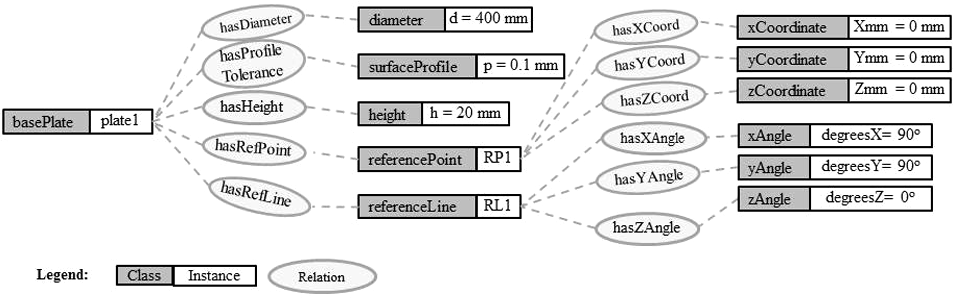
Instances of classes.
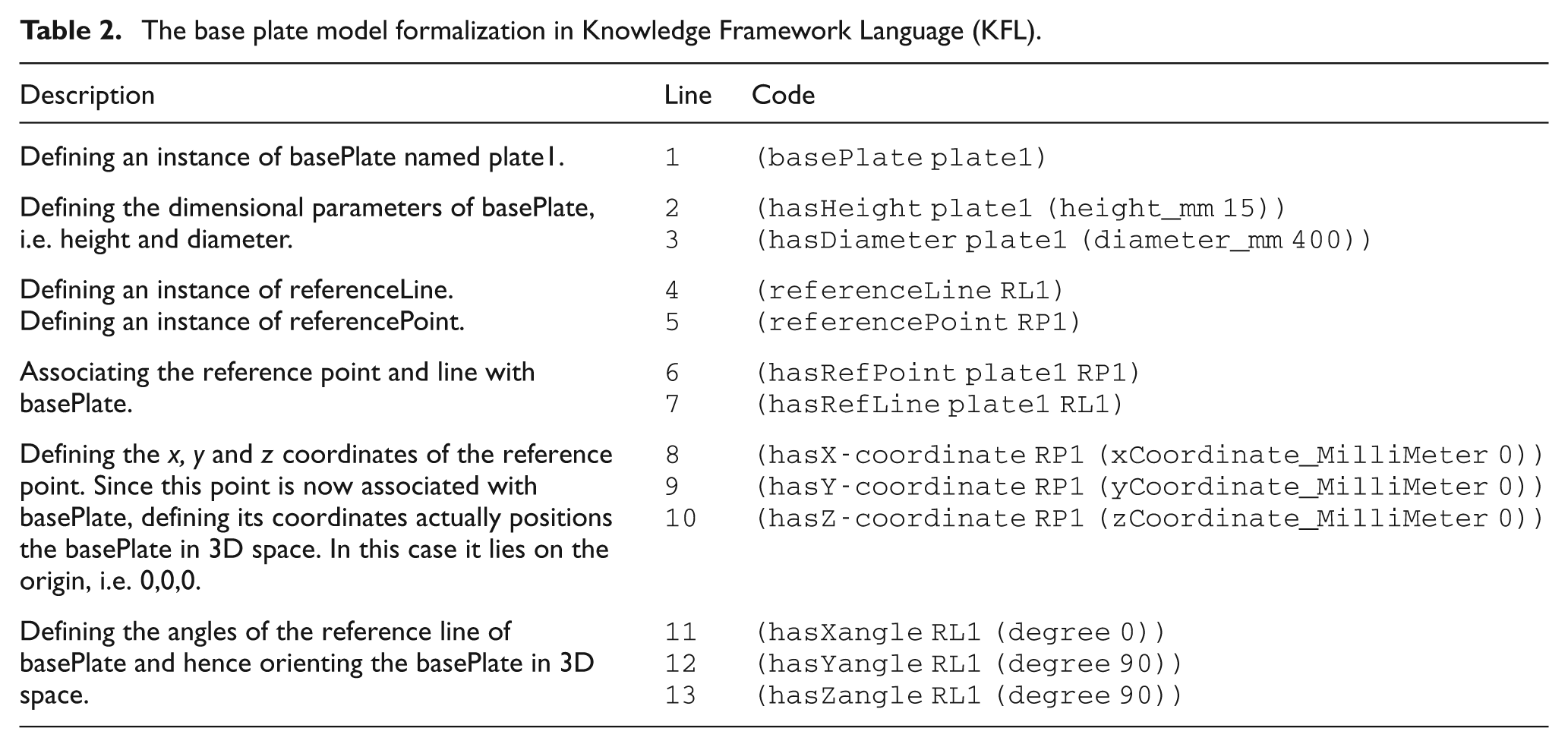
The base plate model formalization in Knowledge Framework Language (KFL).
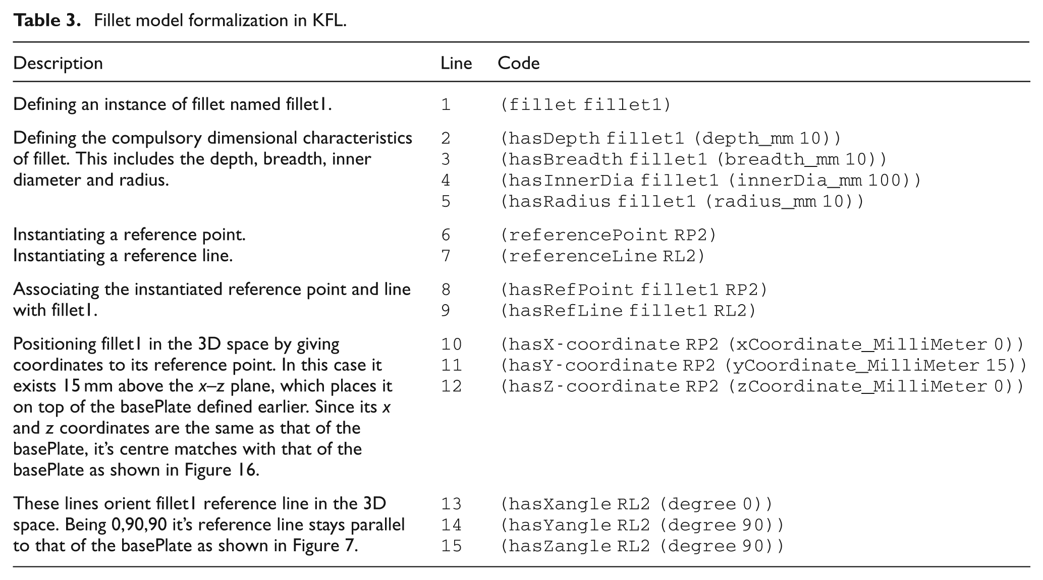
Fillet model formalization in KFL.
In the next section, this ontological model is formalized by using Common Logic based on the KFL as the development formalism.
Common Logic-based ontological feature and product model
ISO standard 24707 20 defines a family of logic-based languages under the name of Common Logic. 21 The preference of Common Logic, in this work, over other commonly used ontological formalisms is owing to its high expressive power and the easy-to-understand, plain English-like syntax. It derives its expressive power from its capability to bind up to five concepts into one relation. None of the contemporary ontological formalisms offer such an easy way of defining highly complicated relations and axioms. This liberty tendered by Common Logic makes it most suitable for expressing relations and constraints as complex as are found in typical manufacturability problems.
One of the syntaxes of Common Logic given in this standard is Common Logic Interchange Format (CLIF). 20 KFL, which is the formalism used here, is actually a syntactic layer that sits on top of an extended syntax of CLIF called ECLIF (Extended CLIF). 22 A KFL ontology features four main components that fulfil the requirements of ontology building as described in the previous section. These four components are its properties, relations, functions and facts. If the 5-tuple of Gruber 7 is revisited then the following is the equivalence.
Class definitions–KFL properties. For example, the feature concept ‘fillet’ is defined as
Which says that there is a class named ‘fillet’, that is an instance of ‘type’ and its super feature is a class named ‘features’.
Relations definitions – KFL relations. For example, a relation between a class named ‘basePlate’ and another class named ‘diameter’ is defined as
Which says that a binary relations ‘hasDiameter’ exists between the classes ‘basePlate’
and ‘diameter’.
Function definitions–KFL functions. For example, a measurement unit is defined by using KFL function as
Which says that the ‘diameter_mm’ is a unary function that takes real number values for the class ‘diameter’.
Instance definitions–KFL facts. For example, the facts about the ‘basePlate’ class can be written as
These two lines say that there exists an instance of the class ‘basePlate’ named ‘plate1’ and it has a diameter of 400 mm. It is important to note here that the concepts basePlate, relation hasDiameter, and function diameter_mm, need to be defined first in the ontology before they are used to build this fact.
Axiom definitions–a combination of KFL properties, relations and functions. For example, a rule to ensure a complete definition of a ‘basePlate’ instance is written as
This rule is a hard integrity constraint hence ‘IC hard’ in the last row. The rule says that if there exists a basePlate then its diameter and height should both also exist. The prefix FDN in the first line is the context in which the class basePlate is originally defined. FDN here denotes the context of foundation ontology.
For a relatively detailed description of the way ontologies are written in KFL see Changoora and Young. 23 Tables 2 and 3 give an example of how a feature can be completely defined in this formalism. The feature defined in Table 2 is a basePlate along with all its dimensional and positional parameters. In the same way the feature ‘fillet’, along with its dimensional and positional parameters, is modelled in Table 3. Figure 7 illustrates how these features, according to their modelled positional and dimensional parameters, exist in the 3D space.
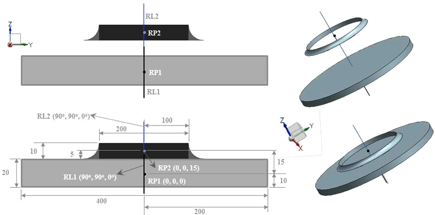
Modelled basePlate and fillet.
Manufacturability verification
So far the definition of individual features has been explained. To define a manufacturability rule, however, a feature integration and dependability declaration is required. Consider an example where an elongated surface has to be machined in one single turning operation as shown in Figure 8. Experience from the case study shows that the cutting tool tip has a certain life, after which the operation is terminated for tool tip resharpening or changing. This disruption in the turning operation leaves a mark on the surface of the part being turned. In this situation a major manufacturability limitation is the overall surface profile tolerance. If the plate arm is too long the tool will have to be lifted from the surface for sharpening or replacement during the operation, which limits the value of surface profile tolerance that can be achieved. If a bigger and heavier tool with longer life is used, owing to a bigger tool tip, it limits the value of fillet radius that can be achieved in an uninterupted single operation. When all of these situations occur simultaneously, i.e. a long arm length, a small fillet radius and a small value of overall surface profile tolerance, this component becomes impossible to manufacture. In this case the manufacturing knowledge base needs to contain a manufacturability constraint that is understood by the designer, despite having different feature perceptions. Table 4 gives the details of an integrity constraint that defines this manufacturability limitation.
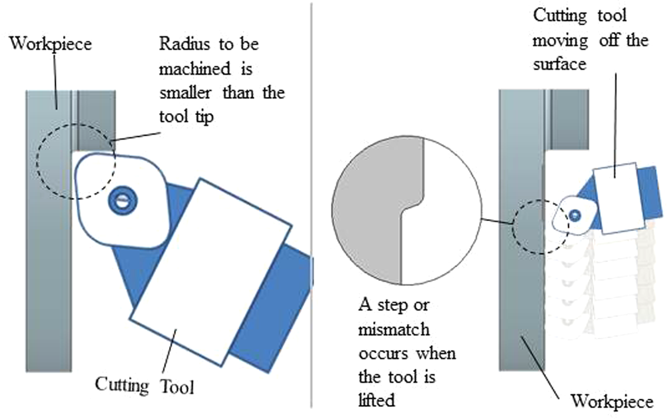
Modelled manufacturability problem.
The formalized manufacturability rule.
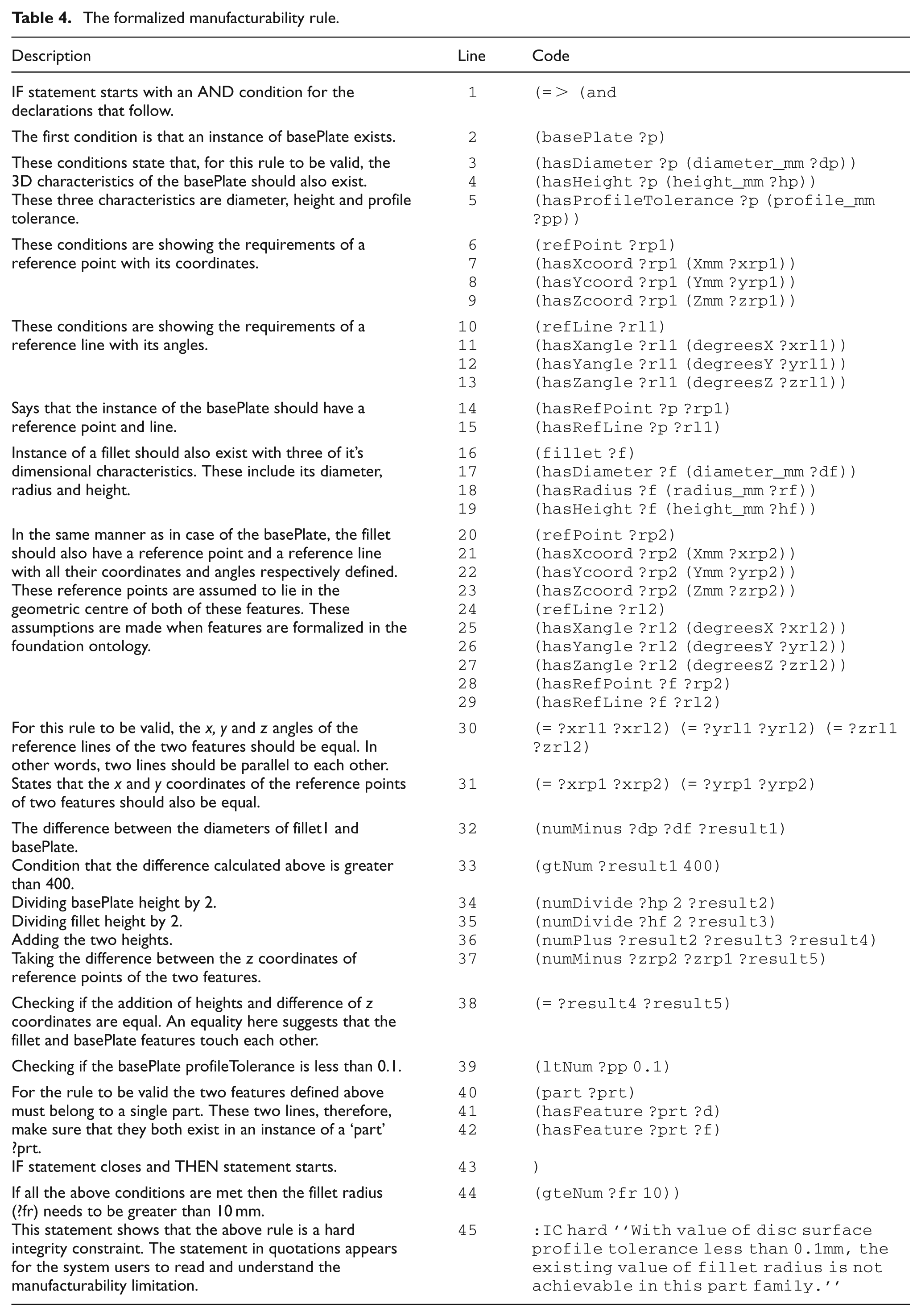
The integrity constraint described in Table 4 has two main parts. The first 43 lines comprise the IF part, while the last two come in the THEN part. Lines 1 to 43 define the inter-feature dependency for which the condition in line 44 should be fulfilled. The first line states that the first condition for this constraint to be true is that a basePlate instance should exist. Lines 2 to 5 add the conditions of the necessary dimensional characteristics of the basePlate instance. Lines 6 to 15 define a reference point and a reference line and associate these positional parameters with the basePlate instance. In the same way lines 16 to 29 define the conditions of the existence of a fillet along with its dimensional and positional characteristics. Up to this point the two features are defined separately. Now, in order to make it an integrated turning feature, some positional conditions are to be stated for the constraint to be valid. This is done in lines 30 to 38. For a clear picture of how the two features join refer to the dimensional and positional values shown in Figure 7. It can be seen in the figure that if the coordinates of RP1, which is the reference point of the basePlate, are set to 0,0,0, and that of the fillet reference point RP2 to 0,0,15, then the two features are aligned as shown provided their reference lines are perpendicular to the x–y plane. Since it is predefined in the ontology, the reference points of these features lie exactly in their geometrical centres. Therefore, for these two features to be perfectly aligned the x and y coordinates of RP1 and RP2 should be equal, while the z coordinate of RP2 has to be the sum of half of the height of the basePlate and half of the height of the fillet. This sum comes out to be 15 as shown in Figure 7 and this is exactly what is being stated in lines 30 to 38. Line 39 declares the condition of base-plate profile tolerance to be less than 0.1 mm. Lines 40 to 42 define the final condition of these two features belonging to a single part or component. When all the conditions up to line 42 are met, the system then checks for the fillet radius and fires the integrity constraint in case it falls below 10 mm. In an interoperable knowledge-sharing system this constraint cautions the designer of the manufacturability limitations.
Discussion
The example explained above demonstrates how an engineering component is translated into the form of a feature-based ontological product model. It also shows how manufacturability constraints are associated with this model. The proposed methodology works in a computer-based knowledge-sharing system where the manufacturability constraints are written by the manufacturers using their own shape feature perception, while the product model is generated by the designers with their understanding of a component and its features. To make the process of manufacturability analysis automatic, a computerized system needs to be put into place to caution the designer at the design infancy stages whenever a manufacturability constraint is violated. This can be achieved by first providing the design and manufacturing people with a set of agreed upon shape feature concepts and then giving them enough freedom to use these concepts as building blocks for developing their own ideosyncratic product models. Once these product models are in place with associated manufacturability constraints, the process of concurrent engineering takes place between the computers instead of humans and any design incompatibility issues are dealt with on a real-time basis. Freedom in the use of concepts means designers and manufacturers are free to use their own perceptions of features and products while building the formalized knowledge base. This gives rise to the issue of interoperability that is an essential requirement of a computerized concurrent engineering system. A verification mechanism is, therefore, required to mediate between the two domains. Although the use of common concepts itself is aimed at acquiring interoperability, a verification system complements this interoperability by reconciling conceptual and terminological differences between design and manufacturing domains.
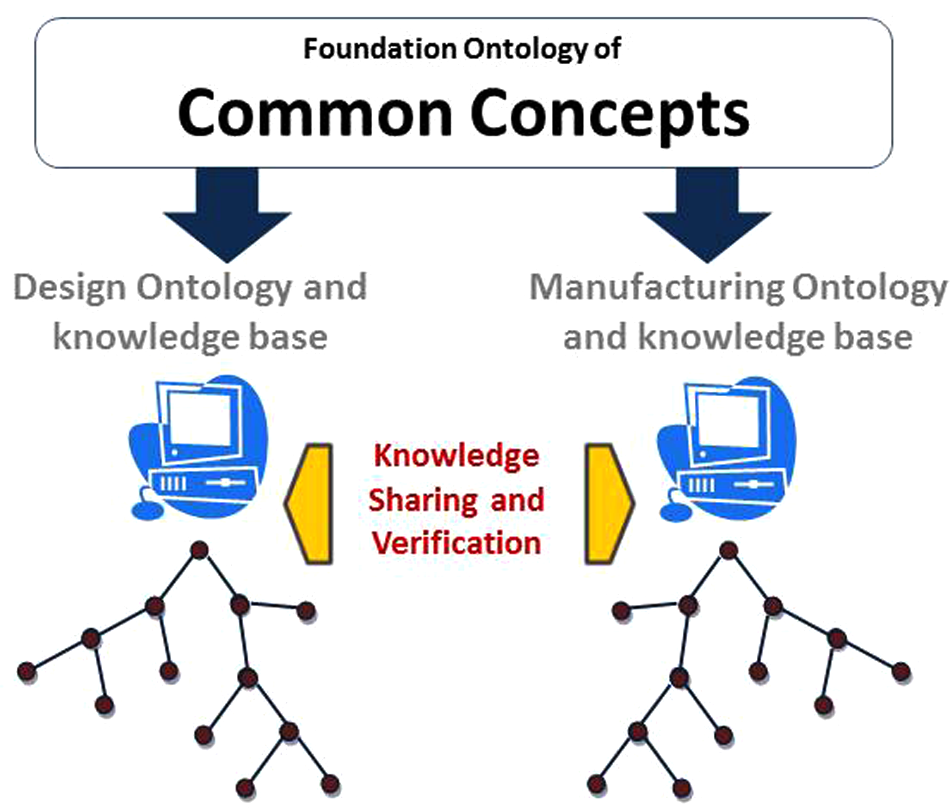
This whole idea has been put to test in a project entitled ‘Interoperable manufacturing knowledge system’ (IMKS). The ontological modelling method proposed here is a small but significant part of the IMKS project, which researches the problem of semantic interoperablity between departments involved in the manufacture of a product. As depicted in Figure 9, it features a foundation ontology of core manufacturing concepts and two domain ontologies developed by using these concepts. The common foundation provides a shape feature library for the design and manufacturing domain ontology builders. The work done in the IMKS project uses NX as the CAD application and an ontology editor named IODE (integrated ontology development environment) as the ontology and knowledge-base builder. The IMKS project aims to link the product models and manufacturability knowledge existing in the form of ontologies with the CAD model existing in NX. For that to be possible, an ontological product and manufacturability knowledge-modelling method is required and the propositions in this article attempt to fulfill that requirement
Foundation ontology-based knowledge-sharing system.
The interoperability is achieved at three different levels here. First of all, the use of ontologies makes the communication between independently developed applications more efficient. This is because ontologies provide a basis for shared meaning through their hierarchical structure and logic-based relations among concepts held in that structure. Second, commitment to a foundation ontology further assures that similarity is embedded in independent knowledge bases during their development. This is accomplished by providing a set of core manufacturing concepts for the domain ontology builders to use and thus leaves a traceability of domain concepts in the foundation ontology. This traceability proves especially useful when, owing to conceptual, perceptual, or terminological differences discussed in this article, the concepts in a domain ontology appear differently. Third, to resolve these semantic differences, a verification system mediates between the design and manufacturing ontology, as shown in Figure 9. It is this verification system that is responsible for making the manufacturability constraints visible to the designer at the very instant of feature modification or creation.
Conclusions
Experience from industry clearly suggests that interoperable knowledge-sharing systems are the need of the hour. These systems are required to work on the principles of concurrent engineering to keep the designer informed of any manufacturability issues during the early design stages. The use of ontologies to develop such a system has a potential to improve the semantic interoperability, and thus provide a means for seamless knowledge sharing. Existing work in the area of product modelling shows that the use of ontologies in product modelling is rare, especially when shape features are used as a modelling unit. The methodology presented in this article combines the use of ontologies with the feature-based design of engineering products. This combination provides an interoperable platform for shareable product modelling through ontologies, while feature-based designing simplifies the manufacturability knowledge association with these ontological models. The product and manufacturability knowledge examples shown in this article demonstrate the use of this methodology and thus validate its usefulness and workability.
Footnotes
This research is funded by the Loughborough Innovative Manufacturing and Construction Research Centre (IMCRC) and is being conducted in partnership with our industrial collaborators.