
Abstract
Double nosing is a cold forming process used in the assembly of spherical plain bearings. In order that future bearing product introductions are better facilitated using a virtual process model, with the aim of reducing extensive prototyping, testing and costly design and process changes, the modelling capabilities of pertinent analytical and computational approaches should be evaluated. For example, there are several existing analytical approaches that were developed for the prediction of the forming loads, an important consideration when assessing the capacity of the press machines and die design, but these are generally only valid for thin sections in nosing. In this paper, for a specific bearing size on the limit of a thin/thick section, the validity of the forming load predictions is assessed through a comparison with experimental data taken from a forming press, and in comparisons with two-dimensional (2D) and three-dimensional (3D) finite element analysis (FEA) results. The modelling capabilities of the FEA approach are examined, including the evolution of maximum stresses in the bearing components, interface pressures on dies and temperature rises created during the double nosing cycle. The computational time to obtain the solutions and the validity of some key initial assumptions are discussed, including the selection of the coefficient of friction.
Introduction
Cold metal forming processes have been used for many years to produce precision component parts that have a near-net-shape, high structural integrity and good surface finish. Nosing, also referred to as tube end forming, is a simple variant of the cold forming process utilised in the manufacture of a wide range of components e.g. tube connectors, revolution vessels and hollow spheres. It is also a key process for the assembly of spherical plain bearings that are extensively used in the aerospace sector in roles such as helicopter pitch controls and inter-blade damper mechanisms. In the process, a tube of metal, or blank, made from a steel alloy that is deformable at room temperature, comprises the outer race of the bearing. It is pressed along its axis by a set of identical domed dies wherein it encapsulates the other pre-assembled bearing components; a self-lubricating composite liner (phenolic and PTFE-impregnated glass fibre) and the inner race, to provide a low-friction bearing with high stiffness (see Figure 1). The conventional plain diameter on the outer race of the bearing (not shown in Figure 1) is subsequently created after the nosing process using cylindrical grinding to provide a precision fit into the bearing housing. Practically speaking the process is termed ‘double nosing’ in the application described here, as both ends of the blank are formed simultaneously using identical dies. The forming load, material properties, blank design and tooling geometry and its velocity all influence the conformity of the assembly and residual bond pressure that the composite liner experiences after nosing. High interface pressures accelerate liner wear and can lead to vibrations in the bearing assembly. Bearings that fail torsional friction inspection limits require reworking at the end of the production line.
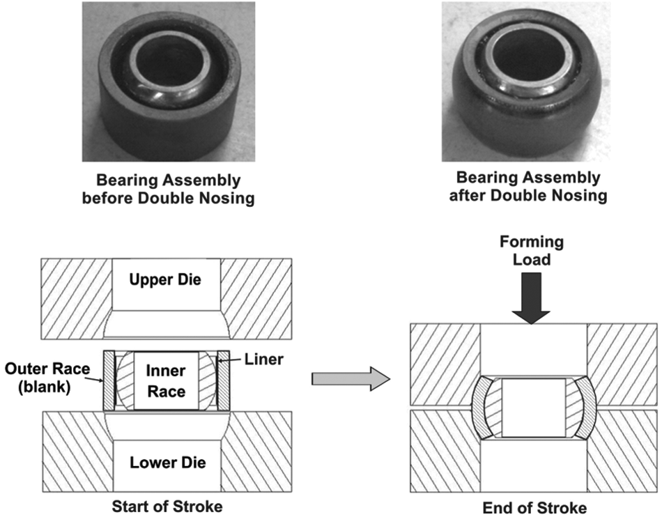
Double nosing process used in the assembly of spherical plain bearings.
Although simple in nature, cold forming processes are generally complex to model accurately. 1 This makes the rapid evaluation of tooling design, the setting of process parameters and accurate determination of the resultant forming loads required and subsequent tooling stresses difficult to establish early in new bearing introduction projects. Furthermore, manufacturing engineers must assess whether the forming loads are within the safe capacity of the presses available in-house or whether investment in new presses is required. The stress fields the tool experiences directly relate to are tool life and potential failure, whether the failure mode is fatigue or fracture due to overloading.2,3 Any failure of the tooling can cause bottlenecks and production downtime. 2 Metal flow and subsequent forming loads vary substantially with small changes in friction and temperature, resulting in malformed components 1 and during the nosing operation, the tube thickness can increase with local bending, and the compressive stresses can lead to defects such as wrinkling, buckling or splitting of components. 4
Traditionally, a time-consuming trial-and-error approach supports tool and component design in cold forming. 3 A study by the company collaborating in this project that manufactures spherical plain bearings found that knowledge in the key areas of material data requirements, selection and validity of the various models that can be used to characterise the double nosing process can lead to an improvement in the costs and development times of future product introductions. The current costly and lengthy experience-based bearing introduction processes would essentially be replaced with virtual and validated simulations as a rapid and less costly alternative.
In this paper, analytical modelling and finite element analysis (FEA) approaches will be applied for the prediction of the forming loads on an established high volume production bearing. The results from all modelling approaches will be compared to experimental data recorded from a force transducer on the press machine in order to evaluate accuracy. In particular the modelling capabilities of FEA will be examined in terms of the stresses, interface pressures and temperature rises exhibited during the nosing cycle. The computational time for solutions to be generated, and the validity of some key initial assumptions e.g. coefficient of friction selection and the thin/thick nature of the nosed blank, will also be presented. The overall applicability of the modelling approaches and their capabilities will be discussed, and the benefits they provide the product introduction team will lead to their inclusion in the virtual process model.
Data for nosing process modelling
Component and process data
The initial blank material shape for the outer race to be nosed is essentially a tube, with 15° chamfers on both ends to facilitate engagement with the upper and lower dies. A lubricant, zinc pyrophosphate, is used to reduce friction and wear on the dies. The upper die translates downward force at a constant strain rate until a stop set in the press program is activated, deforming the blank and liner to match the profile of the inner race. The outer race (or blank) material to be double nosed is AMS 5643, a martensitic, precipitation-hardened stainless steel that provides an outstanding combination of high strength and hardness along with excellent corrosion resistance, and is a material commonly used in the aerospace sector. It also has good fabrication characteristics and can be age hardened by a single step, low-temperature treatment.
The average mechanical properties of this steel were experimentally determined in-house using compression testing on a small sample size of standard test specimens, 5 to model the material’s true stress–true strain behaviour using equation (1). 6 This equation is valid from the onset of plastic deformation and assumes that strain hardening occurs from the very start of plastic deformation, and is often referred to as the flow equation or Hollomon’s equation. Little variation in the parameters for this model (<1%) was observed on repeat testing of specimens, or indeed at different strain rates, measured between 0.1 and 0.5 mm/min

where
It should be noted that the precise geometry and the material properties of the associated composite liner and dies are commercially sensitive information. For modelling purposes, the stiffness of the liner compared with that of the nosed blank (outer bearing race) is very small, and therefore its contribution in the prediction of the forming load will be neglected in all subsequent analyses.
Friction modelling
In nosing, the mechanical energy (load and displacement) is dissipated by friction and plastic work performed to deform the blank. Plastic deformation results from three mechanisms: 7
bending at the contact point between tube and die;
compression in the ortho-radial direction;
friction between tube and die during the whole forming operation.
The forming limit is set by the initial parameters and nosing conditions such as strain rate or friction. Lubrication is therefore a non-negligible factor. Two models are used to represent the frictional behaviour of the material/die interface in the nosing process. Both models consider that the friction stress can be determined via a simple constant coefficient. The first one is Coulomb’s law8–10 in which the friction stress is deduced from the normal contact pressure by the use of a coefficient

where
The second model is the law of constant friction7,11 in which the friction stress is deduced from the shear stress of the material by the use of a coefficient

where
The friction factor
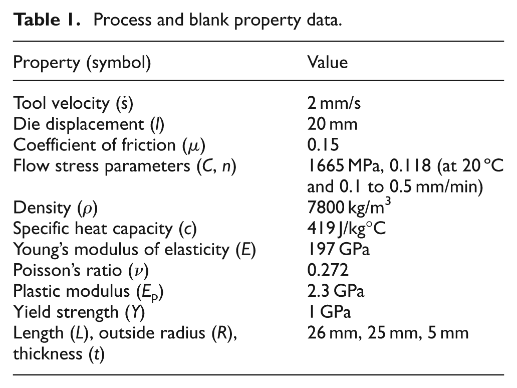
Process and blank property data.
Methods to predict the forming load
Modelling assumptions
The double nosing process used in spherical plain bearing assembly is similar to that described in Alves and Martins 11 for the manufacture of thin-walled hollow spheres, although as seen in Figure 1, only a partial sector of a complete sphere is required. The following analytical approaches to determine the forming load are considered valid for thin-walled sections in general. Thin-walled means that the radius is at least five times the tube thickness which implies that the stress in the radial direction is small compared to other stress components. The blank dimensions used in the current study are on this ratio limit, and therefore results could be subject to some inaccuracies as clearly the stress in the wall thickness could be significant. No studies have been conducted on component thickness values in the transition area between thick and thin walls, and the analytical models may not apply to the case discussed here. Tang and Kobayashi 14 investigated thick-walled nosing using thick shell elements in FEA, although they did not present any analytical work to support their findings. Here, the validity of the application of the analytical models will be verified and will be useful results in comparisons with FEA and experimental data. The assumptions for the validity of these analytical methods are as follows:
the stress in the radial direction is small;
the blank material strain hardens from the start of deformation;
the Tresca failure criterion applies;
the Coulomb friction model applies;
the blank conforms fully to the die.
Figure 2 shows a schematic diagram of the nosing process and relevant parameters used in the mathematical treatment of the analytical forming load models that follow. The schematic effectively shows a one-eighth model of the actual double nosing process, as symmetry occurs in all three Cartesian planes.
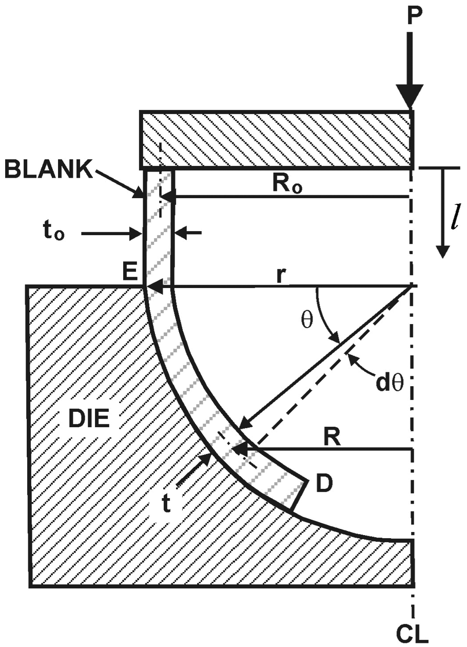
Schematic of the nosing process and parameters used.
Work formula
The work formula 6 can give load approximations for simple uniaxial processes under frictionless conditions. The main principle can be compared to tube nosing using conical dies. The aim of including this approach is to obtain a first idea about the order of magnitude of the nosing forming load. The work formula is given by

where W is the homogeneous work necessary for the plastic deformation, V is the volume of the element, σ is the true stress and ε is the true strain.
Inserting the flow stress equation (1) into equation (4) and integrating gives

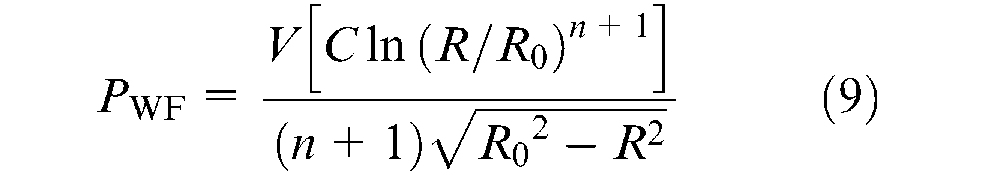
Equation (5) gives the plastic work W at a particular strain. The forming load derived from the work formula PWF is given by

where
The displacement is obtained from the change in radius by simple algebraic manipulation for a spherical die

where R and R0 are the current and initial mid-thickness radii of the blank, respectively.
In the nosing case, the relevant strain is the circumferential strain, εθ is given by

Therefore, substituting equations (5), (7) and (8) into equation (6), the forming load P can be approximated by
The volume of the element V is taken to be equal to one-half that of the initial blank volume. The work formula will provide the forming load for one side only, so for the double nosing process, the load is doubled.
Lower and upper bound methods
Lower bound method
The principle of an upper or lower bound analysis is to approach the correct load value by giving a maximum and minimum possible forming load. If the assumptions and equilibrium equations are valid, the experimental forming load will fit within this interval. The following mathematical treatment is developed from Reid and Harrigan 10 and Lu and Yu. 15 For the Tresca failure criterion, σ θ ≥Y, σ r 0, σ θ > σ x > σ r , where σ θ , σ x and σ r are the stresses in the circumferential, meridional and radial direction, and Y is the yield strength. Considering the material is rigid and linear hardening, the hoop stress σ θ can be written as

where Ep is the plastic modulus.
The volume conservation (incompressibility) condition states that

where
From the normality rule4,6 the meridional strain increment

or

where t and t0 are the current and initial thickness of the blank, respectively.
Assuming the normal stress in the radial direction is negligible (i.e.

and in the meridional direction it is given by

where p is the contact pressure between the blank and die, θ is the angle of curvature of the die and r is the die radius.
Combining equations (14) and (15) and eliminating p, the lower bound formulation is
Replacing
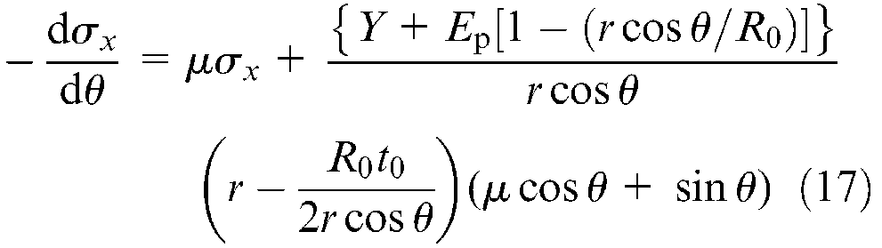
Equation (17) was implemented in Maple and numerically solved for

This load must then be multiplied by a factor of two to apply to double nosing.
Upper bound method
The approximate upper bound forming load, PUB is derived from the law of conservation of energy, that is, the rate of work of the applied loads equals the sum of the rates of energy dissipated in bending, compression and interface friction

where
The rate of energy dissipated in the meridional bending (plastic deformation) can be written as
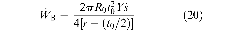
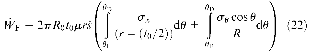
The rate of energy dissipated in the circumferential compression from the end of the nosed blank (D) to the die entrance (E) can be written as
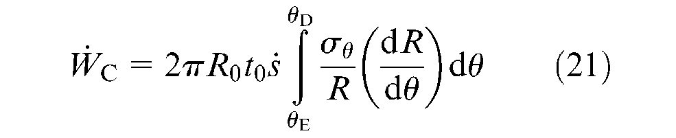
The rate of energy dissipated in frictional contact can be written as
The hoop stress term σθ is given by equation (10), the meridional stress σx by equation (15) and the tool velocity term
Approximate method
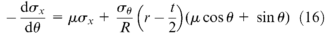
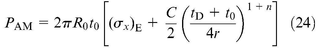
The following approximate method is taken from Manabe and Nishimura 9 with some additional data necessary to perform the forming load calculations taken from Reid and Harrigan. 10 The equilibrium equation of an element of the nosing zone is given by
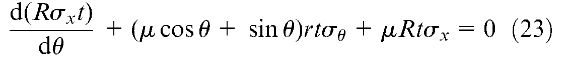
The meridional stress
FEA
The axisymmetric and three-dimensional (3D) models were both developed using Abaqus Explicit. The geometry of the dies, inner race and blank tube to create the outer race, were taken from manufacturer’s engineering drawings using mean dimensions for the purpose of modelling. The composite liner’s thickness was accounted for, but not its mechanical properties in the assessment of forming load, as stated earlier. The dies and inner ring were modelled as rigid components, and the blank as being deformable. Both FEA model types took into account the heat produced by both plastic deformation and frictional effects. A finite sliding formulation was preferred to a small sliding one for modelling friction. In Abaqus, the penalty method is a version of the Coulomb model in which a small elastic slip can be allowed when the surfaces should be sticking. 16 Although the frictional behaviour between the inner ring and blank, and between the blank and dies is different in reality, there should be no tangential relative movement between the first two so the frictional behaviour is not a significant parameter for this contact. Consequently, the same contact properties were applied to all contact surfaces. The boundary conditions were related to the reference points (RPs) of the components, as shown in Figure 3. Note, the blank profile is omitted in Figure 3(b) for clarity, but is the same as that shown in Figure 3(a) revolved through 360°. Each component was assigned its own boundary conditions, except the blank, since it remains in its initial position due to symmetrical contact with the dies from the very beginning of the nosing cycle. The inner race was fixed to prevent any translation of the blank; also, the coaxiality of all elements was intrinsically maintained in the axisymmetric model.

(a) 2D axisymmetric and (b) 3D FEA model geometries and RPs.
The mesh density used in any FEA model is a trade-off between accuracy and computation time. All the elements of the assembly have to be meshed, including the rigid parts, though the meshing options are different for the two model types. In the axisymmetric model, a global seeding of approximate size unity (Abaqus’ automatic seeding) was applied, and it was assigned to the discrete rigid element type. The blank’s mesh has to be fine, at least in the contact zones. Since it appeared that the calculation time for this model remained very short (less than 120 s) even with a fine mesh, the seeding was performed at a much denser level. The external chamfers were assigned 10 elements each and the external surface was assigned 100 elements. The rest of the edges were automatically seeded with a global size of 0.3. The chosen element family was Explicit axisymmetric stress from which the linear Quad elements of first-order accuracy were selected. The rest of the parameters were set to their default values. The mesh technique was structured quad-dominated which led to the final mesh. The final mesh was dense enough to obtain a satisfactory accuracy and avoid the inconsistencies that appeared with the first, rougher meshes.
A dense 3D model mesh increases the computation time much more significantly than for the two-dimensional (2D) axisymmetric model. Since there is no significant deformation occurring by contact between the liner (equivalent to the inner race) and the sleeve, the former was meshed automatically with a global size of two. Discrete rigid elements of Quad type with other default values were assigned to the race, together with a free mesh (because the structure was too complex for a structured mesh) with medial axis algorithm. This gave a regular and symmetrical mesh. The dies were carefully meshed because of the importance of their contact with the blank. They were manually seeded, fine around the contact zone and coarsely in the unused areas. The dense portions were assigned 80 elements each on the circular edges (whole circles) while the same element type as the inner race was allocated to the whole part. Finally, the blank had to be assigned a very fine mesh because as in the axisymmetric model, this mitigated inconsistencies. The circular edges were allocated 240 elements each and the mesh was carried out with the sweep technique and the medial axis algorithm. The chosen element family was explicit 3D stress in which the Hex type (eight-node linear brick) with reduced integration was selected. The other parameters were set to their default values. The blank, being a simple geometry, use the hex elements.
To run the models, displacements were applied linearly over the 10 s of the operation, according to an amplitude rule using the relevant material property data provided in Table 1. Figure 4 provides the Von Mises stress in the blank component using both the 2D and 3D FEA models. The stress patterns are similar; however, Figure 5 compares the evolution of the Von Mises stress over the nosing cycle time of 10 s using the optimised mesh density for both FEA models. The results are comparable at the end of the nosing stroke, being within 30 MPa of each other, or a 2% difference, although a marked deviation in the stress during the early stages of the nosing cycle is evident. It is also noticeable that the blank does not show signs of pure bending at the end of the nosing cycle. This is because the maximum stresses are not located about the centreline of the blank thickness (CL in Figure 4), which should lie half-way between the outer and inner blank dimensions for pure bending as defined by the neutral axis. This suggests that the stress state is complex, with additional circumfrential and axial stress components that are influenced by frictional contact conditions.
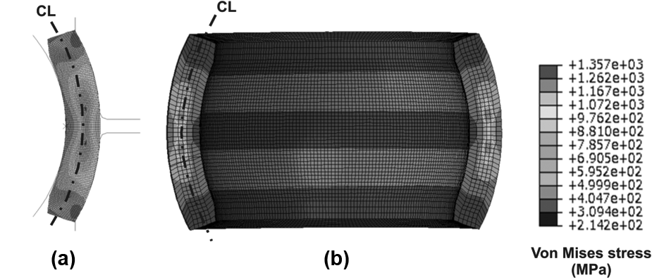
(a) Von Mises stress distribution in the blank using (a) 2D axisymmetric and (b) 3D FEA models.
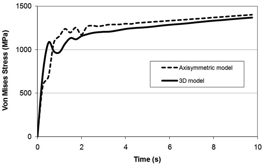
Evolution of Von Mises stress in the blank using 2D axisymmetric and 3D FE models.
Results
Forming load predictions using experimental data
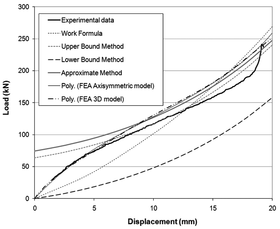
The analytical and computational models for the prediction of the forming load for nosing were reviewed in the previous section. Next, for the specific case described in Table 1 (geometry, material properties, etc.), a comparison of these predictions will be presented together with experimental data taken from the nosing press. The experimental data is an average over a small number of trials, with an overall variation of less than 1%. It is assumed that this variation is a combination of the systematic error found in the force transducer integrated into the press, and the small variation in the measured flow stress, rather than any process inconsistencies. Figure 6 shows the results for the comparison of forming load for the double nosing process. The general trend is similar for the approximate and upper bound models giving satisfactory results at the higher displacement values when compared with the experimental curve. The lower bound approach underestimates the forming load considerably and the work formula provides satisfactory results only at the latter stages of die displacement. The use of these analytical models is very much dependent on the thin/thick-walled assumption, and this could introduce some significant errors. Only a comparison with the FEA can tell if the results are valid. Less than a 1% difference is observed between the 2D axisymmetric and 3D FEA models for the maximum forming load, and both FEA models deviate from the experimental result with increasing displacement.
Double nosing forming load predictions compared with experimental result with respect to displacement.
All approaches provide a maximum forming load prediction within 10% of each other, although the evolution of the forming load is quite different for the upper bound and approximate methods which have an initial offset load of between 60 and 75 kN. The offset is significant because of the assumption of a thin-walled section when in fact it is on the limit of thin and thick. It is evident that the experimental curve has a steep gradient change towards the end of the stroke, indicating that the press stop may not be optimally set, but this is the current setup of the apparatus. Direct comparison of the analytical and FEA approaches with the maximum forming load is therefore not a precise indication of model accuracy, and this point reinforces the need for a more thorough modelling approach such as the one currently being proposed. Note that the gap in data at the beginning of the experimental curve is due to the nature of the press. The software registers the data when the sensors start to detect a load, which is around 30 kN. The non-registered displacement was extrapolated and assumed to be about 1.5 mm.
Other FEA results
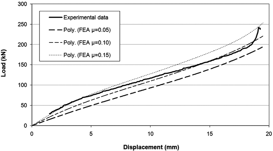
As previously discussed, similar results for the 2D axisymmetric FEA model and full 3D model were observed for the prediction of the forming load, and therefore all subsequent results in this section use the 2D model in order to take advantage of the speed of these computations. First, a review of a change in the initial coefficient of friction µ from that initially assumed (0.15) was conducted. Additional values of µ = 0.05 and 0.1 were implemented in the FEA model and compared with the experimental data, as shown in Figure 7. The most appropriate value for the coefficient of friction is located between 0.10 and 0.15. A slight overestimation of the forming load is safer than a slight underestimation, however, a variable friction model seems to be required, as suggested by Cora et al. 13 but this is much more complex to implement in FEA.
Double nosing forming load for a range of coefficient of friction values compared with experimental result (2D axisymmetric FEA model).
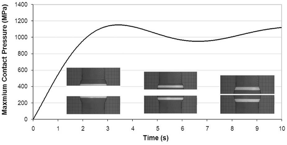
Figure 8 shows that a high sustained pressure is evident in the die from about 3 s into the process cycle. The contact zone on the dies is thin and localised, moving along the die’s working surface. Yu and Zhang 17 identified that the highest contact pressure exists at the die exit in conical dies; this is also the position of greatest die wear observed empirically. Clearly different die designs and the use of different lubricants can influence the amount of wear and its eventual location in the die. The change in pressure can be related back to Figure 7, and further reinforces the point that a variable friction model will be dependent on the interface pressure. This is because generally the coefficient of friction reduces with increased interface pressure between two hard materials with low surface roughness levels. This was observed through the experimental determination of the static coefficient of friction, an important parameter that is used in the torque and force holding capacity of shrink-fitted assemblies. 18
Maximum contact pressure at the die–blank interface with respect to cycle time (2D axisymmetric FE model).
During the nosing process, the extent of the temperature change of the blank must not reach the curing temperature (100 °C) of the composite liner, to which it is in close proximity. The average temperature change of the blank was observed to be 28 °C with the maximum change of 78 °C being localised around the external chamfer on the blank as shown in Figure 9. The temperature change as determined by the energy used for nosing (derived from equation (4)) had a mean value of 52 °C across the blank, showing some disparity with FEA results. Other FEA results (not shown) indicate that apart from the sudden rise at first contact, the temperature increase is almost linear throughout the nosing process. The chamfer features suffer from high plastic deformation and high friction stresses during the nosing process. In the rest of the blank volume, heating is only due to plastic strain and has a very similar distribution to that of the strain. The chamfers on the blank are key to the process setup and hence conformity with the composite liner but have been identified for future design improvement primarily to limit the localised temperature increase in the blank which can degrade the composite liner. FEA is the preferred approach for the prediction of temperature rise levels mainly due to its ability to model fine geometrical features, such as chamfers machined on the blank.
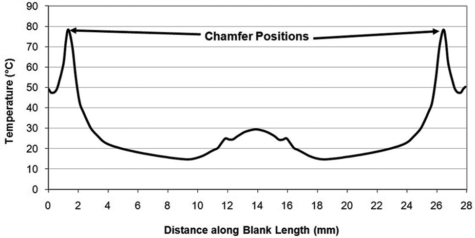
Temperature change along blank outer length (2D axisymmetric FEA model).
Figure 10 shows the change in the Von Mises stress distribution in the blank when the press stop is not optimally positioned; a 2 mm total displacement (1 mm either side) in this case. There is a six-fold increase in the forming load when the press stop is exceeded by 2 mm, and a four-fold increase at 0.5 mm (0.25 mm either side). The precise position of the press stop has major implications on the press itself in terms of overloading and also the die’s tool life. The stress patterns through the blank section also distort further, compare Figure 10(a) and Figure 10(b), showing that an appreciable increase in axial stress has occurred, as the blank is now fully conforming with the dies, frictional contact is minimal and the part is essentially fully compressed in the dies.
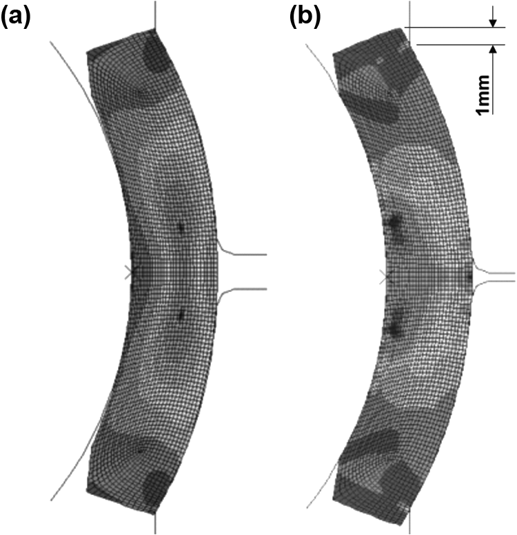
Von Mises stress pattern change from (a) 20 mm to (b) 22 mm relative die displacement (2D axisymmetric FEA model).
In the discussed FEA results, the material properties of the composite liner were excluded, for the reasons stated earlier. However, a brief discussion follows of the impact of including this component in the FEA models demonstrating the geometric conformity of the composite liner after nosing. Figure 11 shows a 2D axisymmetric FEA model of the nosed blank, liner and rigid inner race at the end of the process cycle. It is evident that complete contact of the liner with the blank and inner race surfaces is not achieved. The maximum contact pressure in the composite liner was predicted to be 900 MPa using FEA against a limiting value of 1100 MPa for satisfactory performance of the liner to act as a bearing surface. If the process stop is overrun by fractions of a millimetre, this will cause a breakdown of the composite liner and ‘sticky’ or blocked bearings. A post-nosing operation to recover bearings that fail torsional resistance tests consists in rolling the bearing with a high radial load, whilst applying mechanical torque to the inner and outer ring to force their relative rotation until the correct frictional behaviour is obtained. This reworking operation is time- consuming and costly, and may be avoided through modelling of the process, its parameters, component pressures and loads. However, the composite liner material properties are highly non-linear and anisotropic, and are the focus of future research to achieve better modelling accuracy. In addition, an approximate 2% (5 kN) difference in the forming load was predicted using 2D FEA when modelling the blank at its minimum volume and maximum volume of material as defined by the dimensional tolerances on the part drawings. This could also be significant in assessing the geometric conformance of the liner, and the selection of robust manufacturing tolerances for the blank requires further consideration.
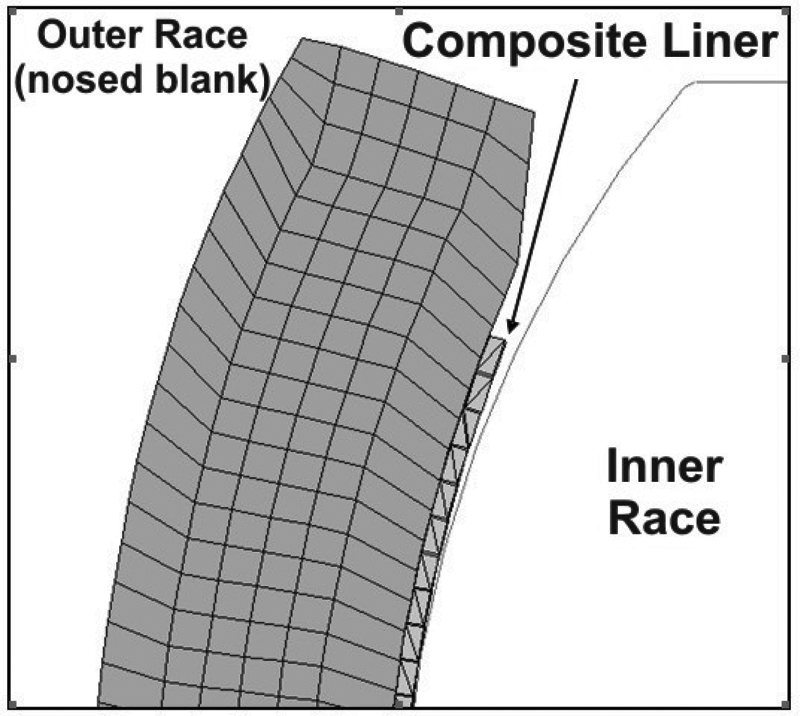
Composite liner contact between inner race and nosed outer race after 20 mm relative die displacement (2D axisymmetric FEA model).
Concluding remarks
Accurate models for the prediction of forming loads for the double nosing process are important for analysing die wear, assembly conformity after assembly and for the determination of press capacity when introducing new bearing designs. The analytical models available in the literature are not applicable to the spherical plain bearing assembly application of the nosing process, as typically the cold formed sections are thick and the radial stress component is significant. A 2D axisymmetric FEA model was found to be accurate and rapid and allowed the determination of other performance measures to address the requirements of new bearing designs. The following attributes of FEA modelling allow it to be successfully used to analyse the nosing process.
Accurate contact pressures, stresses and strains for all components to support failure mode mitigation of components and dies.
A method to determine the coefficient of friction through convergence of the forming load with experimental data from the press. This can then be used for modelling future bearing designs with little or no experimental verification.
Optimum velocity, stroke profile and stop positions for press dies in order to support geometric conformity requirements and also avoid overloading when assessing new materials and blank designs.
Predictions for the temperature increase in the blank due to the nosing process in order that future design features on the blank avoid localised curing of the composite liner.
Prediction of the torsional frictional moment in the bearing assembly with the composite liner. Rapid FEA simulations of the frictional and contact properties of a bearing can be made early in the product introduction process in order to ensure that new designs meet required tolerances.
Future investigations will focus on measuring the non-linear and anisotropic material properties of the composite liner for inclusion in FEA modelling, and the residual stresses after deformation in order to optimise bearing clearances and further assess conformity issues. For greater confidence in future FEA analyses, the models and property data should reflect uncertainty. Stochastic FEA models incorporating Latin hypercube sampling will be used to develop sensitivity analyses for the identification of key process variables under different conditions, as well as providing tolerance bands for nosing force predictions. These predictions will be validated against extensive experimental tests across a range of material types, geometry and processing parameters using the latest production machines. However, to support FEA, it is also desirable to develop an analytical model for nosing when thick sections, as opposed to thin sections, are being formed using double nosing.
Modelling the nosing process to support the specific objectives of forming load and wear prediction, frictional moment modelling and geometric conformity analysis to provide these benefits, will demand a great deal of data management and extensive mapping of the integrated activities in the whole manufacturing system for the bearings, which has already commenced in the collaborating company. The development of a process model for nosing will ultimately allow better risk management, cost reductions, reduced development times and the improved assessment of manufacturing capability prior to production commitment.
Footnotes
Appendix 1
Acknowledgements
The authors gratefully acknowledge the support of Andrew Bell and Tom Heighington of SKF Aerospace Division – Clevedon, North Somerset, UK.