
Abstract
In elliptical vibration cutting, cutting performance is largely affected by the shape and the rotational direction of a micro-scale elliptical trajectory generated at the cutting edge. In this study, change in the shape of the ellipse, which was created by two parallel piezoelectric actuators attached at the tool, was experimentally observed as the excitation frequency to the piezoelectric actuators was increased from 10 Hz to 25 kHz to investigate the effect of the excitation frequency on the elliptical trajectory. For the whole range of experimental frequencies, the major axis of the ellipse becomes tilted, and the aspect ratio of the ellipse is significantly distorted as the excitation frequency approaches the resonant frequency of the elliptical vibration cutting device. To correct the distortion and rotational direction of the elliptical trajectory, an analytical model describing the elliptical path of the tool was developed and verified with experimental results. Based on the analytical model, the distortions in the elliptical trajectories created at various frequencies were corrected for tilt and aspect ratio by changing the phase and relative magnitude of the sinusoidal excitation voltages.
Keywords
Introduction
Advances of information technology and biotechnology demand high-precision micro-machining technology. Micro-molds with micro-patterns such as micro-grooves and pyramid structures are commonly employed for manufacturing the backlight unit of a liquid crystal display, precision lenses, fuel cell separation plates and biochips. Nano-molding, nano-imprinting and micro-forming have been used for creating such micro-patterns, but they require complex pre-processes including masking, etching and a photolithography process. In contrast, micro-machining, which necessitates no pre-process, ensures low thermal shrinkage, gives a high-quality surface finish and provides little restriction on the choice of workpieces.
Elliptical vibration cutting (EVC), also known as two-dimensional vibration assisted cutting, is a novel cutting process for ultra-precision micro-machining, where the cutting tool is actuated to trace a micro-scale elliptical trajectory. In EVC, when the tool is fed into the workpiece, unlike conventional cutting, the cutting edge enters the workpiece in a manner similar to up-milling. EVC is useful for fabricating micro-features for which a cutting depth of under 20 µm is sufficient. The merits of EVC, such as suppressing burr formation and enhancing form accuracy, make it ideal for finishing. Most ductile materials, such as aluminum, brass, copper, nickel alloys (inconel, hastelloy), mold steels and Co–Cr–Mo alloys, can be machined with EVC.
To create an elliptically vibrating trajectory at the cutting edge, Shamoto and Moriwaki,1,2 who invented EVC, used orthogonally arranged dual piezoelectric actuators (PZTs) designed to resonate at a specific frequency at which cutting is intended. Cerniway, 3 Negishi, 4 Brocato, 5 and Kim and Loh 6 constructed EVC devices with a pair of parallel PZTs. Kim and Loh 7 also used a pair of orthogonal PZTs to make an EVC device. In EVC, the vibration amplitude of the cutting tool could be greatly amplified by selecting the excitation frequency near one of the resonance frequencies of the system.2,8 Shamoto et al. 9 also removed cross talks between the two directional vibrations so that each vibration can be controlled independently using two sets of PZTs. Previous studies found that EVC reduced both chip thickness1,2,7,10 and cutting resistance,1,2,6–10 and enhanced form accuracy,2,6–10 surface roughness7,10 and the tool life. 10
Performance of EVC depends on not only the excitation frequency and the vibration amplitude of the elliptical trajectory created at the cutting edge, but also the geometrical characteristics of the elliptical trajectory. 7 The geometrical elements of the elliptical trajectory critically influencing cutting performance would include the slope of the major axis, the aspect ratio and the rotational direction of the elliptical trajectory. Particularly, the rotational direction of the tool along the elliptical trajectory should be clearly determined considering the cutting direction to help the tool discharge chips.
Most previous studies on EVC, however, have focused primarily on the cutting characteristics of the EVC itself. Little research has been performed on distortions in the shape of the elliptical trajectory and the reversal of the rotational direction of the tool as a function of the excitation frequency, although these phenomena have a significant effect on the performance of EVC.
Due to lack of knowledge on the effect of the excitation frequency on the elliptical trajectory, design strategies for the EVC device have predominantly been to drive it at a far lower frequency than its first natural frequency to minimize the shape distortion stemming from resonance,3–5 or to construct it in such a way that a desired elliptical trajectory is generated by superimposing two mode shapes.1,2,8,9 The former significantly restricts the bandwidth of the EVC device and the latter allows for only one driving frequency. EVC is known to produce better machining quality at higher driving frequencies, 7 but as the excitation frequency increases, the shape of the elliptical trajectory is unnecessarily distorted and the rotational direction of the tool is periodically reversed. If the way the driving frequency of the EVC device influences the elliptical trajectory were fully understood, EVC could be performed at a wide range of driving frequencies with a capability of manipulating the shape and rotational direction of the elliptical trajectory for optimum cutting performance systematically.
In this study, the reasons for changes in the shape and reversal of the rotational direction of the elliptical trajectory are investigated through experiments and analytical modeling, and based on an investigation into the nature of the distortion of the elliptical trajectory, a systematic approach to correcting the distortion and the rotational direction of the elliptical trajectory by manipulating the relative magnitude and phase of the driving voltages is presented.
Structure of elliptical vibration cutting device and its vibrational characteristics
Figures 1 and 2 show a photograph and a schematic of the EVC device, which consists of a pair of stacked PZTs (P-888.30, PI, Germany), a tool holder, a bottom fixture and a connecting bolt. The PZTs are compressed between the tool holder and the bottom fixture by a connecting bolt. On the top of the PZT, a stainless steel hemi-sphere is glued, which allows the PZT to make a point contact with the tool holder. This design prevents the displacement of one PZT from being transmitted to the other PZT through the tool holder, minimizing potentially hazardous shear deformation to the PZTs.
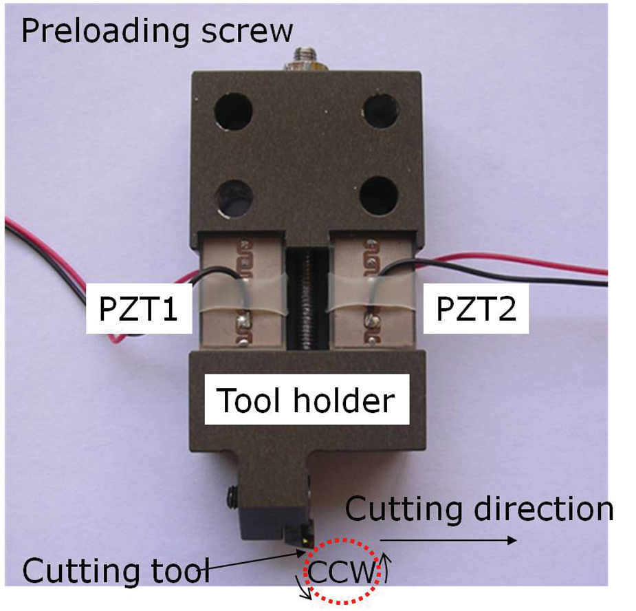
Photograph of an EVC device. CCW, counter-clockwise rotation.
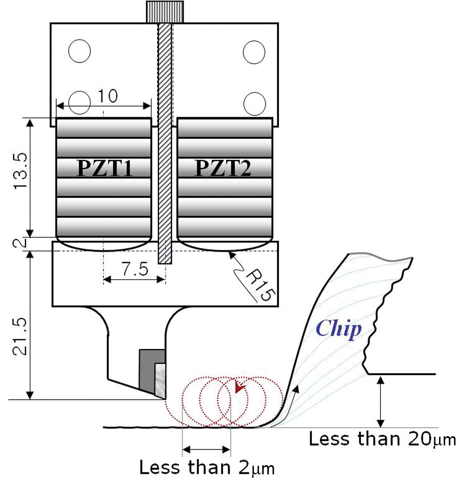
Schematic of an EVC device (units: mm, unless otherwise specified). The size of the vibration amplitude is exaggerated to illustrate EVC process.
When the two parallel PZTs are supplied with sinusoidal voltages of relatively low frequency having a phase difference, typically 90°, PZT1 and PZT2 periodically expand or contract with the same phase as the supplied voltage, causing the tool to move along a micro-scale elliptical trajectory in the clockwise or counter-clockwise direction, depending on the phase difference between the excitation voltages, as illustrated in Figure 3. When the tool is fed into the workpiece for cutting, as a result of the feed of the tool and the elliptical trajectory of the cutting edge, a trochoidal motion is created at the tool, cutting the workpiece in a way similar to up-milling, as shown in Figure 2. In conventional cutting, the frictional force developed between the tool and chip works as a resistant force, whereas in EVC, the upward motion of the elliptically rotating tool turns the frictional force into an aiding force to discharge chips, drastically reducing cutting resistance. Therefore, to effectively decrease the cutting resistance by EVC, the rotational direction of the tool should be determined in a direction to minimize the cutting resistance given a cutting direction (counter-clockwise direction for the cutting direction shown in Figure 1).
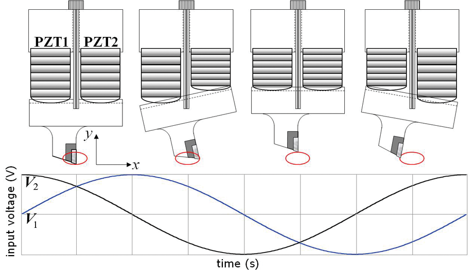
Illustration of generating elliptical trajectory at the cutting edge by applying sinusoidal voltages to two parallel PZT actuators. V1 and V2 are sinusoidal voltages to PZT1 and PZT2, respectively.
To measure the elliptical trajectory of the tool, the displacements of the tool were concurrently measured in the cutting and thrust directions, respectively, using optical displacement sensors (PM-E, Nanotex Corp., Japan). First, overall frequency responses were obtained along the cutting and thrust directions, as shown in Figures 4(a) and (b), with the excitation frequency progressively increasing from 10 Hz to 25 kHz. Subsequently, frequency responses at discrete frequencies were measured, as shown in Figures 5 and 6, including the phase between the excitation voltage and the displacement.
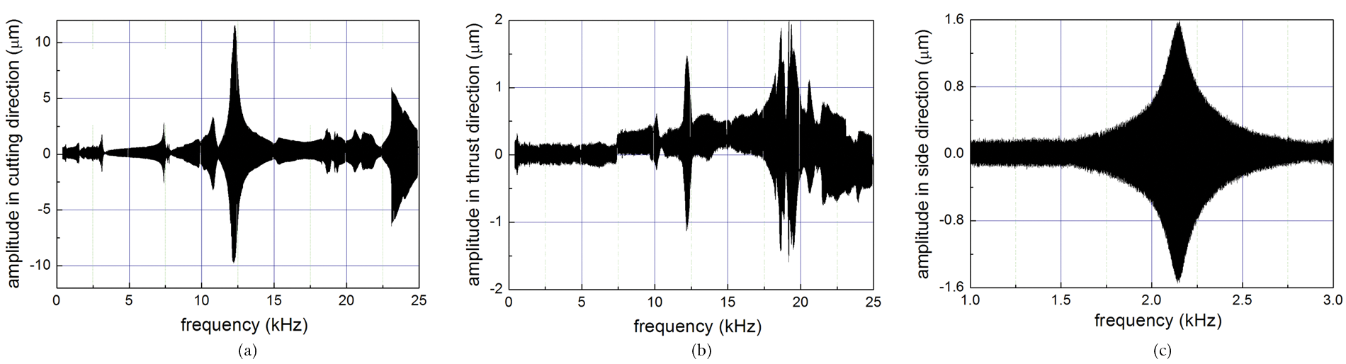
Amplitude versus excitation frequency: (a) cutting direction, (b) thrust direction and (c) side direction.
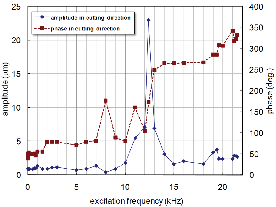
Amplitude and phase in the cutting direction versus excitation frequency.
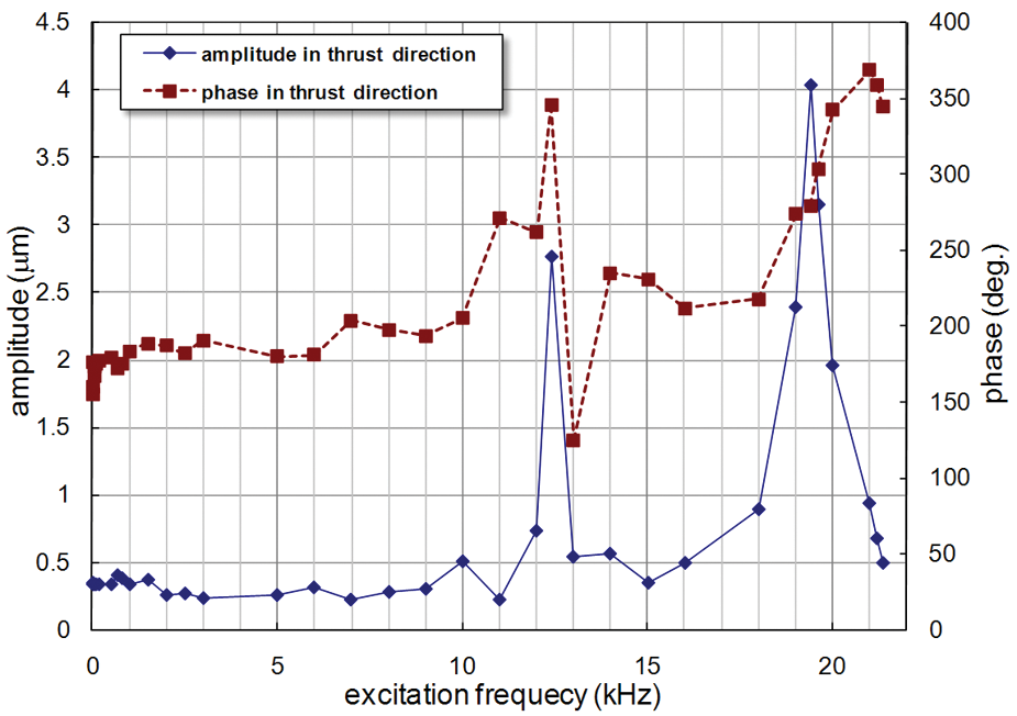
Amplitude and phase in the thrust direction versus excitation frequency.
As shown in Figure 5, the maximum vibration amplitude in the cutting direction occurs at an excitation frequency of 12.4 kHz, at which a phase lag of 90° is also observed with respect to the excitation voltage, indicating that the excitation frequency of 12.4 kHz is a resonant frequency of the EVC device. For the vibration amplitude in the thrust direction, as in Figure 6, two peaks are observed, the first one at 12.4 kHz and the second one at 19.6 kHz. The frequency at which the first peak occurs coincides with the first resonant frequency in the cutting direction, and the phase variation of 180° commonly observed in the vicinity of resonance is not noticed before and after the first peak frequency. Considering both phase variation and coincidence of peak amplitude, these results imply that the first peak in Figure 6 is caused by the flexural resonance at 12.4 kHz and a cross talk exists between the displacements in the cutting and thrust directions. Therefore, it can be inferred that the first peak in the cutting direction is not a resonant frequency. On the other hand, before and after the second peak observed at 19.4 kHz, a phase lag of 180° and the maximum vibration amplitude are shown, which are clearly indicative of resonance.
Figure 4(c) shows the side vibration characteristics measured along the direction perpendicular to both the cutting and thrust directions, which indicates its first resonant frequency at 2.1 kHz. This vibration causes the tool to move out of the cutting plane containing the cutting and thrust directions and, therefore, the frequency at which the side resonance; that is, torsional resonance, occurs should be avoided in choosing the excitation frequency.
Figure 4(a) shows slight non-symmetry at the excitation frequency of 12.4 kHz; greater vibration amplitude in the positive x-direction is observed than the negative x-direction. The non-symmetry appears to be caused by the non-symmetrical design of the tool holder in which the tool holder has more mass distribution in the negative x-direction to accommodate the tool. This non-uniformity in mass distribution would not make a noticeable difference in the low acceleration case, but it seems to create a pronounced effect on the vibration amplitude in the high-acceleration case. Meanwhile, in Figure 4(b), a slight direct current (DC) offset (0.1 µm) of the vibration amplitude is noticed at 7.5 kHz and at 21 kHz. The EVC device has a variety of vibrational mode shapes and as the driving frequency grows, a slight slip occurs at a certain excitation frequency between the tool holder and the PZTs, causing a DC offset of the vibration amplitude.
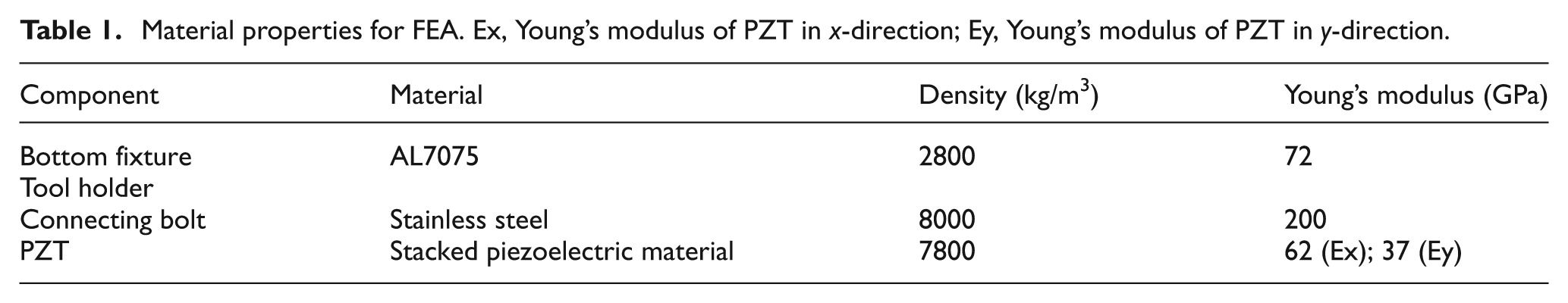
To verify resonance at 12.4 kHz and 19.4 kHz and identify the mode shapes associated with them, finite-element analysis (FEA) was performed using Ansys based on the material properties listed in Table 1. Figures 7 and 8 show the mode shapes from FEA associated with resonance in the cutting direction (flexural resonance) at 10.5 kHz and in the thrust direction (longitudinal resonance) at 23.7 kHz, respectively. Boundary conditions and loading are shown in Figure 9. Estimation errors, 25% for flexural resonance and 18% for longitudinal resonance, appear to result from assuming the stacked PZT as a solid one and rigid-body motion between the PZTs and tool holder.
Material properties for FEA. Ex, Young’s modulus of PZT in x-direction; Ey, Young’s modulus of PZT in y-direction.
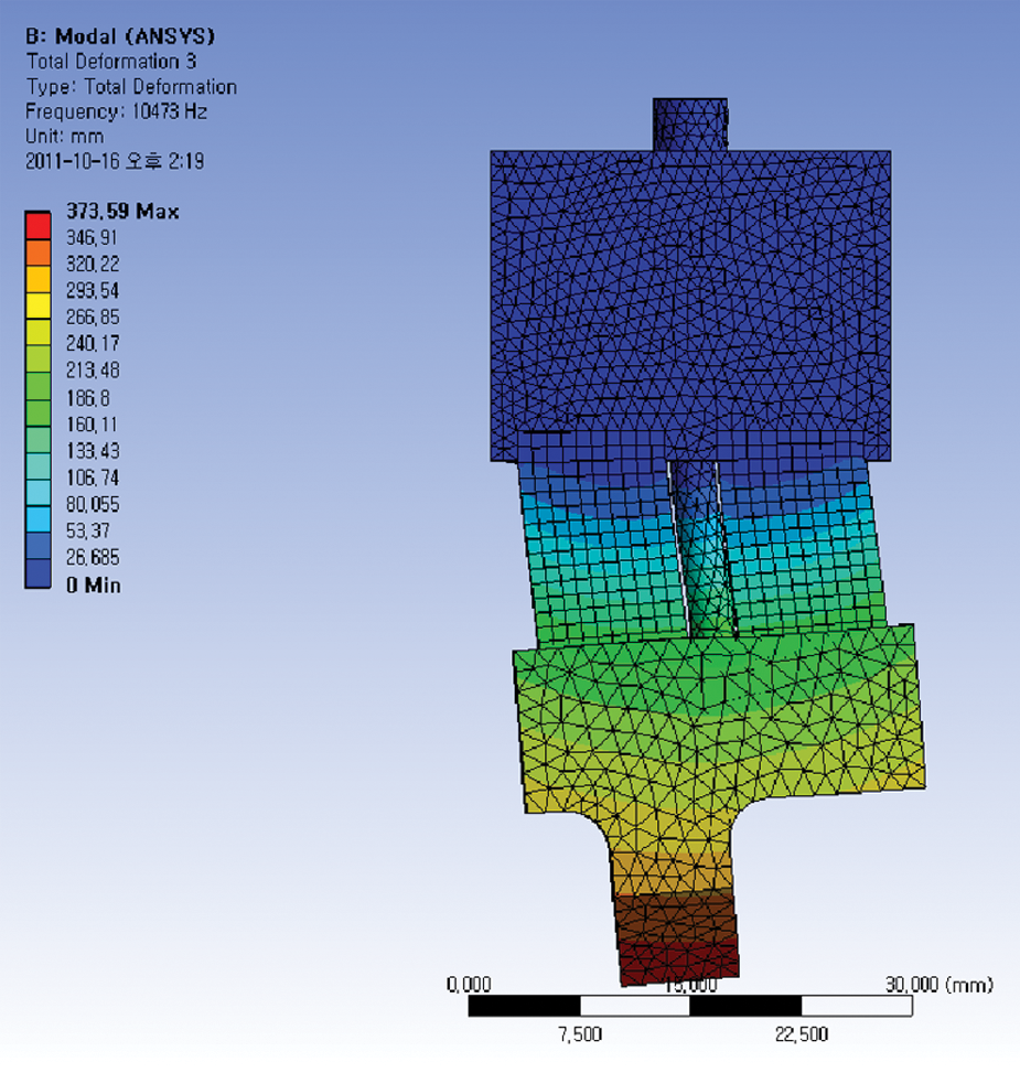
Flexural mode of vibration of EVC device.
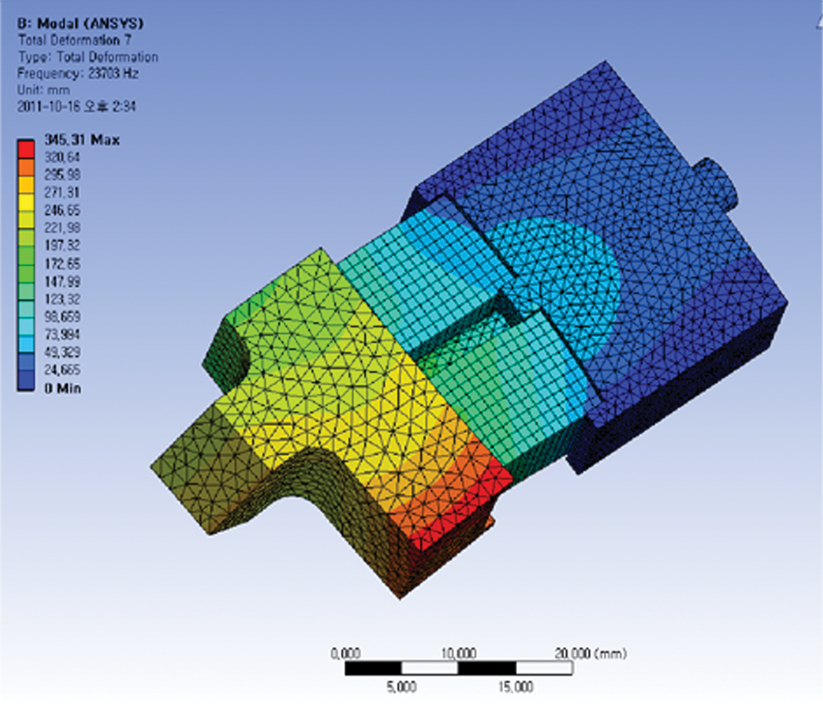
Longitudinal mode of vibration of EVC device.
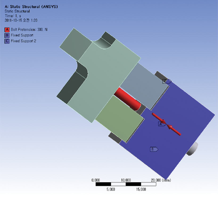
Boundary conditions and loading for FEA.
Kinematical analysis and correction of shape of elliptical trajectory
Kinematical analysis of elliptical trajectory and its measurements
When the two parallel PZTs are supplied with harmonic voltages with a phase difference of 90°, each PZT periodically expands or contracts, as shown in Figure 10, with the same phase imposed between the two excitation voltages, causing the tool to follow an elliptical trajectory if the excitation frequency is assumed to be significantly lower than the first natural frequency of the EVC device. Considering the relatively small cutting resistance encountered in EVC
7
in comparison with the driving force of the EVC device, cutting resistance on the tool motion would be minimal and, therefore, can be reasonably removed from analyzing the elliptical trajectory the EVC device can generate. Therefore, from simple kinematic analysis, the position of the tool (


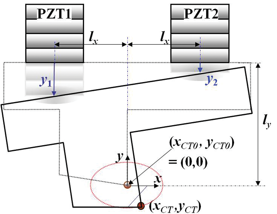
Kinematic analysis of motion of cutting edge.
where lx is half the distance between the centers of the PZTs in the x-direction, ly is the distance between the cutting tool edge and the PZT in the y-direction, and y1 and y2 are the displacements of PZT1 and PZT2, respectively.
Assuming


Equations (1) and (2), which are derived based on the assumptions that the tool holder is infinitely rigid and the mass center of it remains along the y-axis, predict generation of an elliptical trajectory whose major and minor axes are parallel to the cutting and thrust directions, respectively, when the displacements created by the PZTs have a 90° phase difference. To verify equations (1) and (2), the PZTs were energized by the sinusoidal voltages of 90° out of phase at an excitation frequency of 10 Hz. Then, the measured displacements of the tool cutting edge (xCT, yCT) were compared with the right-hand sides of equations (1) and (2). The vibration displacements of the PZTs (y1, y2) were estimated from the voltage supplied to the PZTs. A good agreement between the prediction and the measurement was shown in the vibration displacements in the cutting direction, while a phase was observed in the thrust direction between the measurement and the estimation, as shown in Figure 11. The elliptical trajectory synthesized from the measured vibration displacements shows a tilt in its major axis, as shown in Figure 12. The causes for the tilt of the major axis presumably are elastic deformation of the tool holder, slip between the tool holder and the PZTs, asymmetry of the EVC device, nonlinearities in the PZTs, and so on.
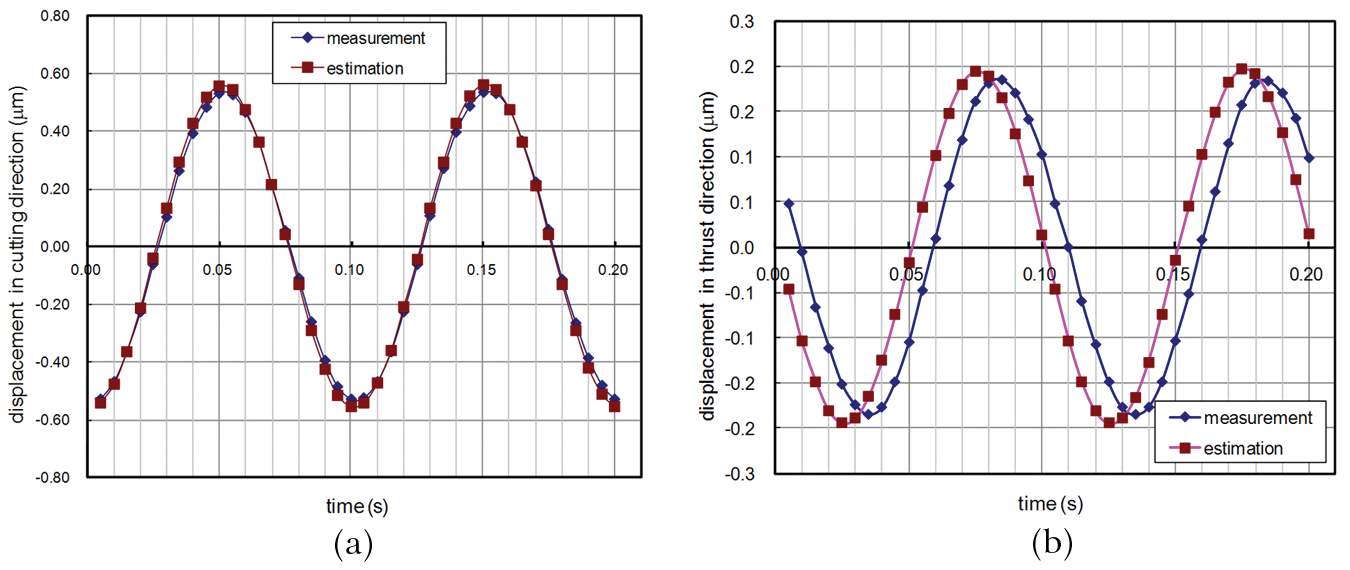
Vibration displacements measured and estimated in the (a) cutting and (b) thrust directions at 10 Hz.
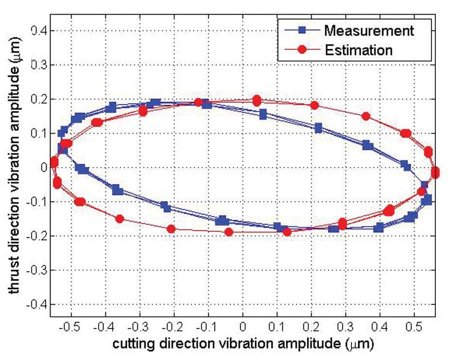
Elliptical trajectory measured and estimated at an excitation frequency of 10 Hz.
Effect of excitation frequency on variation of elliptical trajectory
To gauge the effect of the excitation frequency on the shape and the rotation direction of the elliptical trajectory, the excitation frequency was increased from 10 Hz to 22 kHz, while the excitation voltages and the phase between them were maintained at 8 V and 90°, respectively. As the excitation frequency approaches the first flexural resonant frequency at 12.4 kHz, progressively increasing from 10 Hz to 100 Hz, 1 kHz and 10 kHz, the size of the elliptical trajectory grows more prominently along the major axis, as shown in Figure 13(a), and the rotational direction of the trajectory was the counter-clockwise direction for all cases. At an excitation frequency of 12.4 kHz, flexural resonance significantly affects the displacement of the cutting direction in both the vibration amplitude and the phase with respect to the excitation voltage, rendering the elliptical trajectory a reciprocating line, as shown in Figure 13(b). As the excitation frequency was increased beyond 12.4 kHz, the rotation direction of the trajectory suddenly reversed itself instantaneously after the excitation frequency grew beyond the flexural resonant frequency at 12.4 kHz. The rotation direction of the trajectory at 13 kHz is shown in Figure 13(c). When the excitation frequency was further increased to 14 kHz, it was observed, as in Figure 13(d), that the tilt angle of the elliptical trajectory became a positive value in contrast to negative tilt angles observed at the excitation frequencies up to 13 kHz. Until the excitation frequency reached a longitudinal resonance frequency at 19.6 kHz, no significant change in the shape of the elliptical trajectory was observed, other than slight variation in the tilt angle and the size of the ellipse. At the first longitudinal resonant frequency at 19.6 kHz, longitudinal resonance occurring along the thrust direction influenced the displacement of the thrust direction in the same way as the flexural resonance affected the displacement in the cutting direction, transforming the elliptical trajectory into a reciprocating line as in Figure 13(e). As the excitation frequency grew greater than the longitudinal resonant frequency, as shown in Figure 13(f), the rotational direction of the trajectory reversed itself again, back to the counter-clockwise direction, which was observed at the low excitation frequencies.
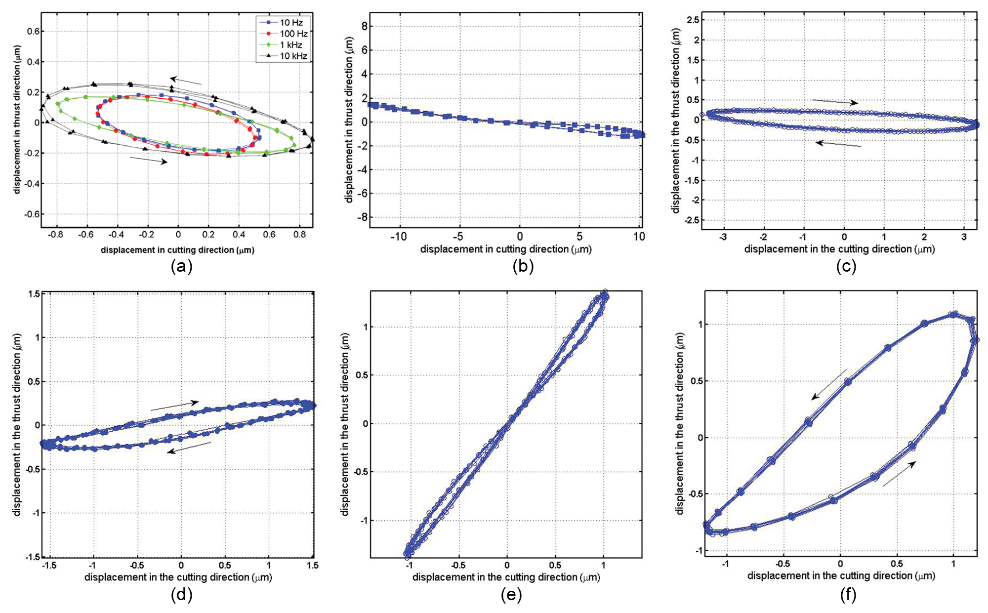
Elliptical trajectories at various excitation frequencies from 10 Hz to 20 kHz. The arrow indicates the rotation direction of the trajectory. (a) At excitation frequencies of 10 Hz, 100 Hz, 1 kHz and 10 kHz, (b) at the first flexural resonance (12.4 kHz), (c) at an excitation frequency of 13 kHz, (d) at an excitation frequency of 14 kHz, (e) at the first longitudinal resonance (19.6 kHz) and (f) at an excitation frequency of 20 kHz.
As the excitation frequency of the sinusoidal voltages to the PZTs increases, it inevitably passes through resonant frequencies of the EVC device, exciting various modes of vibrations such as flexural, longitudinal and torsional modes. The flexural and longitudinal vibrations occur on the same plane where the cutting and thrust directions are defined, but the torsional vibration causes the tool to deviate from this plane, unfavorably affecting the cutting performance. Therefore, resonant frequencies at which the torsional mode of vibration occurs should be avoided in EVC, whereas the flexural and longitudinal resonance frequencies could be put into practical use, provided that the effect of resonance on generating the elliptical trajectory was fully understood.
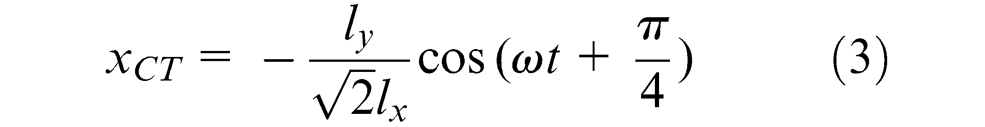
Modeling of elliptical trajectory of cutting edge
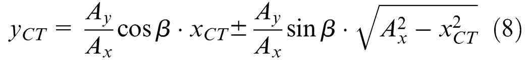
Equation (5), which describes the elliptical trajectory of the tool in EVC, can be applied only when the excitation frequency is far below the resonance frequency of the EVC device. Considering that EVC is generally performed at frequencies of the order of tens of kilohertz, equations (3) and (4) should be modified to accommodate both the amplification of the vibration amplitude and the additional phase lag introduced by the effect of resonance. Therefore, equations (3) and (4) can be further generalized as equations (6) and (7), based on an experimental observation that the shape and rotational direction of the elliptical trajectory are determined by relative magnitude of the vibration amplitudes in the cutting and thrust directions as well as the phase difference between them. To obtain a trajectory of the cutting edge on the x–y plane, equation (6) is substituted into equation (7), yielding equation (8), which shows the resulting elliptical trajectory is a linear combination of the equation of a line (the first term of equation (8)) and the equation of an ellipse (the second term).


where
A phase difference of 90° between the cutting and thrust direction displacements; that is, β in equation (7) makes the tool rotate in the counter-clockwise direction, as illustrated in Figure 10.
It is, therefore, inferred from equation (8) that the tilt of the elliptical trajectory is governed by the slope of the line
Hence, when the phase difference between the cutting and thrust direction displacements β is equal to 90°, the tilt of the elliptical trajectory disappears, making the major axis of the elliptical trajectory parallel to the cutting direction of the tool, when 90° < β < 270°, the major axis has a negative slope as in Figures 13(a)–(c), and when 0° < β < 90° or 270° < β < 360°, the slope becomes a positive value as in Figures 13(d)–(f). The phase also affects the aspect ratio of the elliptical trajectory together with the ratio of the vibration amplitudes as in the second term on the right-hand side of equation (8).
To verify equation (8), the vibration displacements along the cutting and thrust directions were simultaneously measured together with their relative phase difference β at an excitation frequency of 1, 10 and 16 kHz, and the results were substituted into equation (8) to create estimated elliptical trajectories, which are plotted against the measured trajectories for comparison in Figure 14. The estimation curves in Figure 14, which are based on equation (8) using Ax, Ay and β from the measurement data, satisfactorily correspond to the measurements, meaning equation (8) is valid to describe the elliptical trajectory of the tool.
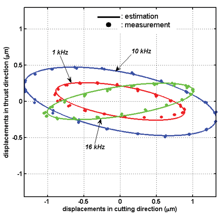
Measurements and estimations of elliptical trajectories at excitation frequencies of 1, 10 and 16 kHz.
Reversal of rotation direction of elliptical trajectory
It is critical to the cutting performance of EVC whether the trochoidal motion of the cutting edge is upward or downward during EVC because the upward motion helps the tool discharge chip, reducing cutting resistance; in contrast, the downward motion obstructs chip discharging. Reversal of the rotation direction of the tool can also be explained using equations (6) and (7). For the coordinates defined in Figure 10, when the displacement in the cutting direction leads the displacement in the thrust direction, the tool traverses in a counter-clockwise direction along the elliptical trajectory according to equations (6) and (7), and when the displacement of the cutting direction lags that of the thrust direction, the direction of rotation of the tool becomes clockwise. Figure 15 shows the phase difference β versus the excitation frequency together with the rotational direction of the elliptical trajectory of the cutting tool, where a positive phase difference indicates a phase lead of the displacement of the cutting direction over that of the thrust direction, and a negative value means vice versa. The rotational direction shifts at 12.4 kHz from the counter-clockwise direction to the clockwise direction without changing the phase difference in the excitation voltages preset to 90°. The rotation direction shifts again at 19.6 kHz to the counter-clockwise direction. The reason for this reversal of the rotation direction is the additional phase added to the phase difference in the displacements by the first flexural resonance occurring at 12.4 kHz and the first longitudinal vibration at 19.6 kHz. The sign of the phase difference between the cutting and thrust displacements β determines the rotational direction of the tool. At excitation frequencies below 12.4 kHz, the phase difference β remains positive at about 120°, except for a sudden decrease at 8 kHz, which appears to be caused by resonance in the side direction, resulting in the counter-clockwise rotation. The sign of the phase difference turns negative immediately after 12 kHz, causing the tool to rotate in the clockwise direction, and the sign remains unchanged until 19 kHz, after which the phase difference becomes positive again and the rotational direction reverses itself, back to the counter-clockwise direction.
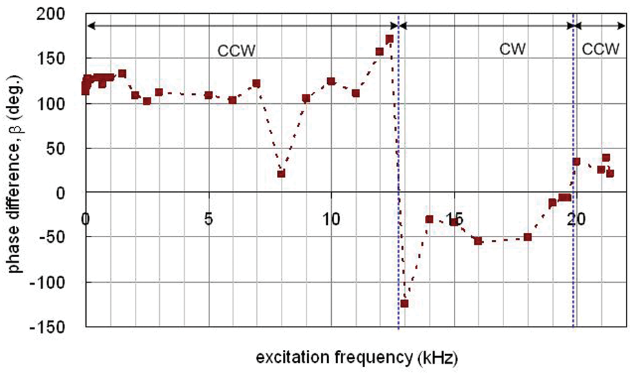
Phase difference between the cutting and thrust direction displacements versus excitation frequency. CCW, counter-clockwise rotation; CW, clockwise rotation.
Shape correction of elliptical trajectory
From low to high excitation frequencies, the elliptical trajectory generated at the tool showed distortions in its shape. At low excitation frequencies, the causes of the distortions are primarily attributed to elastic deformations of the PZTs and the tool holder, micro-scale slip between the PZTs and the tool holder, and asymmetry of the EVC devices. At high excitation frequencies, however, an increase in the vibration amplitude and phase lag resulting from resonance play a critical role in the distortion. To make the most of benefits of EVC, a process of compensation is necessary that corrects the distorted elliptical trajectory into the shape ideal for EVC by modulating the excitation voltages in terms of the phase and relative magnitude. According to the EVC experiments in the previous study, 7 the cutting performance of EVC was found to be greatly affected by the shape of the elliptical trajectory, although an ideal shape for a given cutting condition has yet to be determined. To demonstrate the proposed method of correcting distortions, distorted trajectories were corrected into a shape whose major axis is parallel to the cutting direction and the aspect ratio is 2:1; that is, the length of the major axis of the ellipse is twice the minor axis.
Figure 16 shows the elliptical trajectories compensated for tilt of the major axis and the aspect ratio along with the uncompensated elliptical trajectories generated at various excitation frequencies. At an excitation frequency of 100 Hz as in Figure 16(a), the uncompensated shape shows a 120° phase difference β between the cutting and thrust direction displacements, which caused a tilt of the major axis relative to the cutting direction by 13°. To correct the shape of this elliptical trajectory based on equation (8), the phase difference β is lowered to 90° by decreasing the phase difference between the excitation voltages α from 90° to 60°. Subsequently, to improve the aspect ratio of the elliptical trajectory, the amplitude of voltage supplied to the PZT1 was lowered to 12 V from 15 V. For excitation frequencies of 1, 10 and 16 kHz, similar compensating processes were applied, modulating the phase difference between the excitation voltages α, followed by adjusting the amplitudes of the excitation voltages. The detailed conditions for correction are shown in Table 2 and the results are shown in Figure 16(b), (c) and (d).
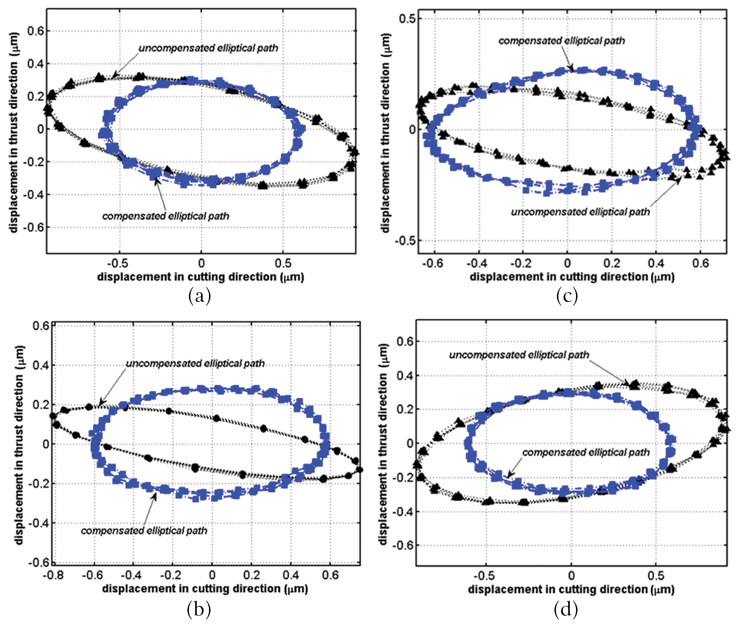
Compensated trajectory (Ax = 1.2 µm, Ay = 0.6 µm) versus uncompensated trajectory. For detailed conditions for generating and compensating elliptical trajectories, see Table 2. (a) Excitation frequency of 100 Hz, (b) excitation frequency of 1 kHz, (c) excitation frequency of 10 kHz and (d) excitation frequency of 16 kHz.
Phase angles and excitation voltages for correcting distorted elliptical trajectory.
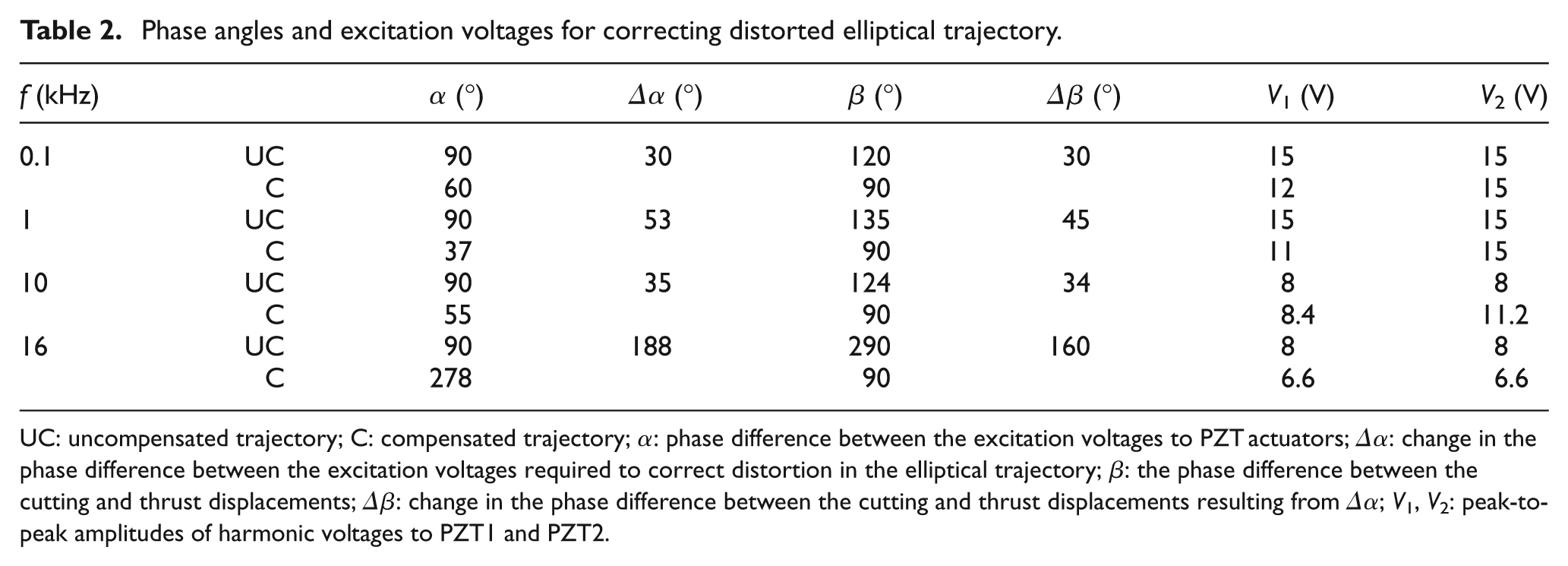
UC: uncompensated trajectory; C: compensated trajectory; α: phase difference between the excitation voltages to PZT actuators; Δα: change in the phase difference between the excitation voltages required to correct distortion in the elliptical trajectory; β: the phase difference between the cutting and thrust displacements; Δβ: change in the phase difference between the cutting and thrust displacements resulting from Δα; V1, V2: peak-to-peak amplitudes of harmonic voltages to PZT1 and PZT2.
For the excitation frequencies of 100 Hz, 1 kHz, 10 kHz and 16 kHz, the changes in the phase difference Δα for correction between the excitation voltages turned out to correlate well with the changes in the phase difference Δβ for correction between the vibration displacements in the cutting and thrust directions as shown in Table 2. Therefore, the slope of the major axis can be easily set to a desired angle and the rotation direction of the trajectory can also be varied to either the clockwise or counter-clockwise directions depending on the cutting direction, by manipulating the phase difference of the excitation voltages Δα.
Conclusions
To generate an elliptical motion at the cutting edge, sinusoidal voltages of 90° out of phase were supplied to the EVC device, which consisted of dual parallel PZTs and then, with the excitation frequency increasing from 10 to 25 kHz, the change of the resulting elliptical trajectory was observed in terms of its shape and rotational direction. For the whole range of experimental excitation frequencies, distortions in the shape of the elliptical trajectory, such as a tilt in the major axis and an increase in the aspect ratio, were observed. In addition, as the excitation frequency was increased to greater than either the flexural or longitudinal resonant frequencies, reversal of the rotation direction of the tool occurred from the clockwise to counter-clockwise direction or vice versa. The additional phase between the cutting and thrust direction displacements resulting from resonance was found to be a primary reason for reversal of the rotation direction.
To take full advantage of EVC, the shape of the elliptical trajectory needs to be modified for a given cutting condition, and the rotation direction should be clearly defined in terms of the cutting direction and maintained, regardless of the excitation frequency. It was shown analytically and experimentally that the phase difference between the displacements in the cutting and thrust directions β plays a critical role in the shape and rotational direction of the elliptical trajectory generated at the tool.
To create an elliptical trajectory with the major axis parallel to the cutting direction, a first step would be to offset an additional phase imposed to the intended phase difference of 90°. A variation of the phase difference in the excitation voltages Δα proved to correlate well with a change of the phase difference in the vibration displacements Δβ. Therefore, manipulating the phase difference in the excitation voltages α, which is preset to 90°, allows the phase difference in the displacements β to be easily manipulated to correct a tilt of the elliptical trajectory and to change the rotation direction of the elliptical trajectory. Once a tilt in the major axis is compensated, then the aspect ratio of the elliptical trajectory is corrected by changing the relative magnitude of the excitation voltages.
Footnotes
This research was financially supported by Hansung University.