
Abstract
Carbon fiber-reinforced polymer (CFRP) composites are increasingly employed in automotive, aerospace, and related industries to achieve lightweight structural designs. Although friction stir lap welding (FSLW) has been widely utilized for metal-thermoplastic composite joining, most existing studies have focused on static strength and fracture behavior, with limited attention to fatigue performance and dynamic damage evolution. In this work, high-aluminum-content particle-filled PA66 composites were manufactured using an electric-field-activated hot-press sintering process and subsequently joined to 6061-T6 via FSLW. The dissimilar joints consistently failed on the composite side under both static and cyclic loading, exhibiting a static tensile strength of 1935 N. As the composite material governed joint failure, fatigue characterization concentrated on the composite side. At 41.7% of the static strength, the composite achieved a fatigue life of 602,999 cycles. These results demonstrate that the proposed dissimilar FSLW joint possesses promising fatigue resistance, supporting its potential application in lightweight transportation structures. The results also provide a basis for future studies aimed at optimizing interfacial design and enhancing the long-term durability of metal-polymer hybrid joints.
Keywords
Introduction
Lightweight design has become an important strategy for improving structural efficiency, reducing energy consumption, and mitigating environmental impacts in fields such as aerospace, transportation, and automotive engineering. 1 Hybrid structures combining aluminum alloys with polymer composites have attracted increasing attention due to their integration of high stiffness and thermal conductivity of metals with the high specific strength and corrosion resistance of thermoplastic composites. However, the significant discrepancies in physical and chemical properties between metals and polymers pose a persistent challenge to achieving reliable structural joining between low-cost thermoplastics and metals, particularly under long-term cyclic loading conditions.
Among various engineering thermoplastics, polyether ether ketone (PEEK) has been widely investigated for metal-polymer joining because of its high melting temperature, high elastic modulus, and the presence of polar functional groups that can react with metal surface oxides.2–5 PEEK and its carbon-fiber-reinforced composites (CFR-PEEK) exhibit excellent thermal stability and mechanical properties for metal-polymer joining. However, their high material cost and elevated processing temperatures significantly limit their widespread industrial application. In contrast, thermoplastic polymers such as polyamide 66 (PA66) and polypropylene (PP) offer clear advantages in terms of cost and processability.6–9 Nevertheless, their relatively poor thermal stability and interfacial reactivity often make it difficult to form dense and stable interfacial structures during direct joining with metals, resulting in defects such as pores or unfilled regions that degrade joint strength.10,11 Therefore, enhancement strategies including metal particle reinforcement and interfacial activation are often required to improve the joining performance of these low-cost polymers.
Previous studies have demonstrated that introduction of metal particles can modulate the interfacial behavior of polymer composites during metal joining. Derazkola et al. 12 enhanced the mechanical interlocking structure and significantly improved joint strength by introducing nano-alumina particles into AA6062-PMMA joints. Feng et al. 13 reported that incorporating micron-sized aluminum particles into PA66 expanded the molten resin region and reduced interfacial defects during laser joining. However, the limited chemical reactivity of polymer functional groups at conventional processing temperatures, coupled with the presence of stable oxide layers on metal particles, make it difficult to achieve effective chemical bonding between polymers and metal particles. When the particle content exceeds a critical threshold, the particles may disrupt the continuity of the polymer matrix and induce stress concentration at the particle-matrix interface, resulting in significant deterioration of composite strength and toughness.14,15 Thus, in most existing studies the metal particle content in polymer matrices is typically limited to relatively low contents.
If highly filled metal-particle-reinforced polymer composites can be successfully fabricated, both thermal stability and thermal conductivity may be improved. This can expand the process window for joining and enable more stable temperature distributions during welding.16,17 Additionally, a high particle fraction may promote the formation of a continuous particle contact network at the interface, which could facilitate stronger interactions between particles and the metal substrate and even enable localized metal-metal bonding. Lin et al. 18 compared radiative heating sintering and electric-field-assisted sintering for preparing PA66 composites with high aluminum particle contents. Their results showed that when the aluminum particle content reached 50 wt.%, the composite exhibited the highest strength, and the application of an electric field increased the tensile strength from approximately 30 MPa to 60 MPa. More importantly, the electric field promoted interfacial functional-group reactions and strengthened both chemical bonding and secondary interactions at the Al-PA66 interface, thereby improving load transfer between particles and the matrix. These results indicate that electric-field-assisted sintering is an effective interfacial activation strategy for preparing highly filled metal-particle-reinforced thermoplastic composites.
As the static strength of dissimilar joints improves, fatigue performance becomes increasingly critical for ensuring long-term structural reliability. Extensive studies have been conducted on the fatigue behavior of metal-polymer joints prepared by adhesive bonding or mechanical fastening.19–24 Previous research has demonstrated that the fatigue life of adhesively bonded joints is strongly influenced by loading parameters and environmental conditions, such as stress ratio, loading frequency, and temperature. For example, Zhang et al. 25 reported that interfacial debonding propagation dominates the fatigue failure of CFRP-aluminum adhesive joints. However, these traditional joining approaches have inherent limitations, including adhesive degradation, stress concentration around fasteners, and increased structural weight, all of which may adversely affect fatigue performance.26–29
Friction-based joining techniques, such as friction stir welding (FSW) and friction stir lap welding (FSLW), have attracted considerable attention because they produce solid-state joints with relatively low heat input and reduced polymer degradation.30–32 Pinto et al. 33 reported that increasing the loading temperature significantly reduced the fatigue life of friction stir welded AA7075 aluminum alloy joints, while a lower stress ratio also adversely affected fatigue performance. Ogawa et al. 34 found that increasing welding time enlarged the bonding area and improved both the static strength and fatigue strength of aluminum alloy/CFRP joints produced by friction stir spot welding. Nevertheless, studies on the influence of cyclic loading parameters, particularly stress amplitude, on the fatigue behavior of metal-polymer friction stir welded joints remain limited.
In practical engineering applications, many PA66 components are subjected to long-term cyclic loading. Therefore, understanding the fatigue behavior of PA66-based composites is of considerable importance. In particular, the fatigue performance and damage evolution mechanisms of highly metal-particle-filled PA66 composites under cyclic loading remain largely unexplored. In this study, the fatigue behavior and fracture mechanisms of aluminum-particle-reinforced polyamide composites (ARP) are investigated. Furthermore, the static and cyclic load-bearing behavior of friction stir lap welded joints between ARP and 6061 aluminum alloy is systematically evaluated. Particular emphasis is placed on understanding the joining mechanisms and fatigue failure modes of these metal-polymer dissimilar joints, thereby providing insights for the design of reliable lightweight hybrid structures.
Experimental methods
Materials
Spherical aluminum powder (24 µm, CAS: 7429-90-5, ≥99% high purity, purchased from Aladdin), polyamide 66 powder (PA66, 48 µm), silane coupling agent (Model: KH560, NANJIN CHUANSHI CHEMICAL Company, Nanjing, China), and acetic acid solvent (CH3COOH, 36%, AR pure).
Preparation of the ARP composite material
The pH of deionized water was first adjusted to 3.5–4.0 using 36% analytical-grade acetic acid. The silane coupling agent KH560 was then added to the solution and stirred for 10–15 min until a clear hydrolyzed solution was obtained. Aluminum powder and PA66 were slowly introduced into the KH560 solution at a predetermined mass ratio of 1:1, followed by thorough mixing for 5 min to ensure uniform dispersion of all constituents. The mixed solution was dried in an oven at 70°C for 3–3.5 h until a constant mass was reached, corresponding to the total mass of the added aluminum particles and PA66 powder, thereby minimizing the influence of moisture introduced by the hygroscopic nature of PA66. The modified PA66/Al powder was loaded into a 60 mm-diameter graphite mold and consolidated using an electric-field-activated hot-pressing-assisted technique sintering (FAPAS) furnace under controlled temperature and a pressure of 6.4 MPa to fabricate composite sheets with a final diameter of 60 mm. The powder compact was first heated to 270°C by radiative heating and held for 20 min. The temperature was then reduced to 250°C, after which an external electric field was applied to maintain the temperature at 250°C for 20 min. The detailed sintering temperature program is shown in Figure 1. The sheet thickness increased proportionally with the amount of powder added. The overall preparation process is shown schematically in Figure 1. Schematic diagram of ARP composite material forming process.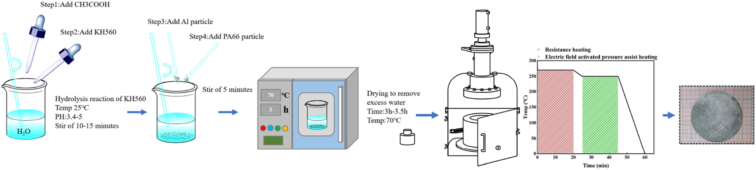
Welding process
Chemical composition of 6061-T6(wt.%).
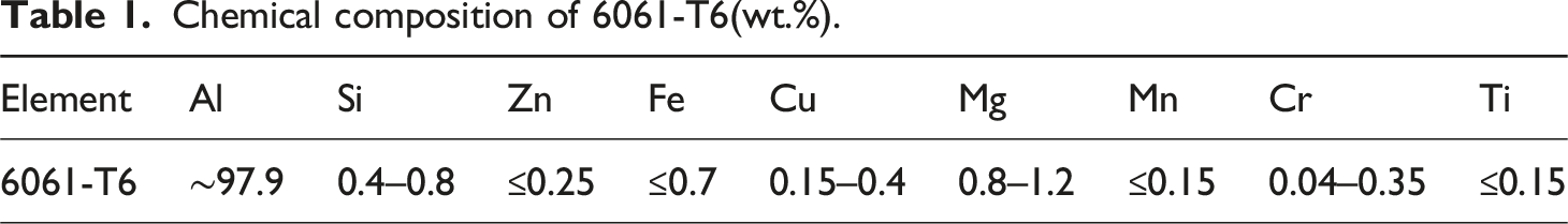
The 6061-T6 aluminum alloy and ARP composite were positioned as the upper and lower plates, respectively, and placed on the advancing side (AS) and the retreating side (RS) with a transverse overlap of 10 mm, as shown in Figure 2(a). Prior to welding, the contact surfaces were mechanically polished and subsequently cleaned to minimize the influence of surface oxides. The fabricated steel pin (Figure 2(b)) consists of a 10 mm diameter shoulder and a tapered thread pin. Its overall length is 1.5 mm, with a tip diameter of 2 mm and a root diameter of 3 mm. The 10 mm shoulder and 2 mm tip diameter ensure sufficient temperature and pressure in the welding region. In addition, the tapered threaded design of the pin effectively promotes material flow. The spiral cutting action facilitates particle migration and enhances the mixing between the metal and polymer matrix, ensuring a more uniform distribution of metal particles within the welding zone and thereby improving the interfacial bonding strength of the joint. Based on preliminary process optimization, the rotational speed was set to 1600 rpm, the welding speed to 30 mm/min, and the tool tilt angle and plunge depth were adjusted to 2° and 1.9 mm, respectively. The temperature variation during welding is provided in the Supplemental Information (Fig. S7- Fig. S8). (a) Schematic diagram of the FSLW; (b) Dimensions of the stirring pin; (c) Dimensions of the shear and fatigue specimens; (d) Dimensions of the ARP-BM specimens for fatigue testing. Unit: mm.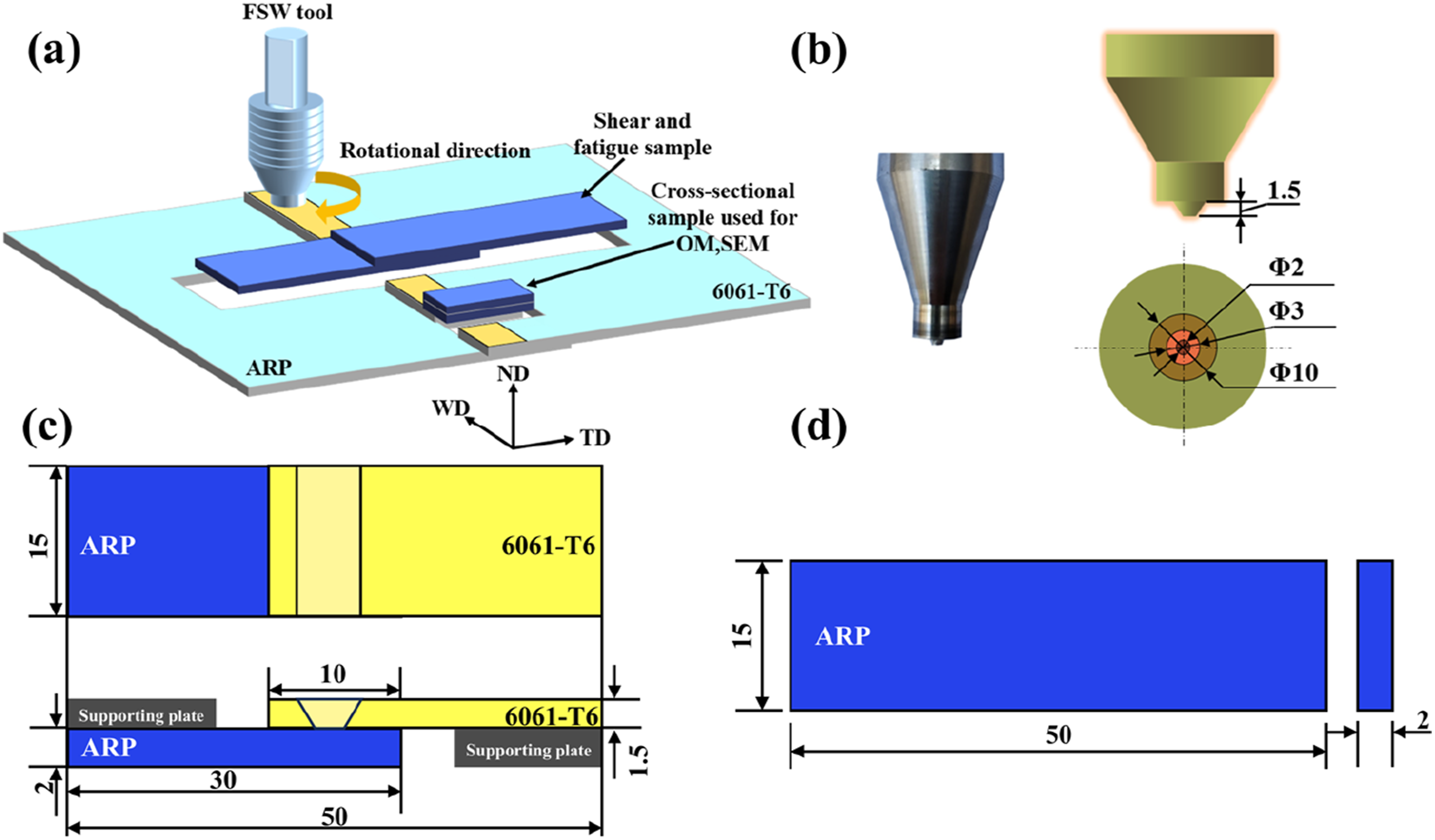
Microstructural characterization
The microstructure and elemental distribution were examined using a thermal field emission scanning electron microscope (TFESEM, Model: JSM-7900F, JEOL Ltd., Japan) operated at 15 kV. X-ray photoelectron spectroscopy (XPS) was employed to analyze potential chemical bond formation at the shear fracture interface of the dissimilar joints (Model: ESCALAB Xi+, Thermo Scientific, USA; 300 W, Al Kα radiation). Energy calibration was performed using the C 1s peak at 284.8 eV (C-C bond) as the reference. All XPS spectra were processed using CasaXPS software with a Smart background correction. Prior to XPS measurements, argon ion etching was applied to the sample surface to remove possible surface contamination and minimize the influence of surface oxygen on the analysis.
Mechanical property tests
Tensile testing of the composite materials was performed in accordance with the GB/T 528-2009 standard, “Determination of Tensile Stress-Strain Properties of Vulcanized Rubber or Thermoplastic Rubber”. The schematic geometry of the tensile specimen is provided in Figure 3. Tests were conducted at room temperature using an electronic universal testing machine (Instron 5969, ITW Group), with the crosshead speed set to 0.5 mm/min. Shear and fatigue test specimens of the dissimilar joints were sectioned perpendicular to the welding direction (WD), as shown in Figure 2(a). To prevent bending during shear deformation, two support plates were installed with dimensions illustrated in Figure 2(c). Shear testing was performed at room temperature on the same Instron 5969 system, with a crosshead speed of 0.5 mm/min. Fatigue testing was carried out under sinusoidal loading at a frequency of 3 Hz and a stress ratio of 0.1, at room temperature (23°C) and ambient humidity conditions. The test was terminated upon complete fracture of the joint. Three parallel specimens were evaluated for each condition to ensure data reliability. In addition, fatigue tests were conducted on ARP-BM specimens for comparison, using the same testing parameters to evaluate their fatigue performance under tension-tension loading. Shims were placed at both ends of the ARP specimens to prevent surface damage at the clamping regions, with the specimen dimensions shown in Figure 2(d). (a) Tensile strength of ARP composite and pure PA66; (b) Fracture surface morphology of ARP composite; (c) Magnified view of Region I.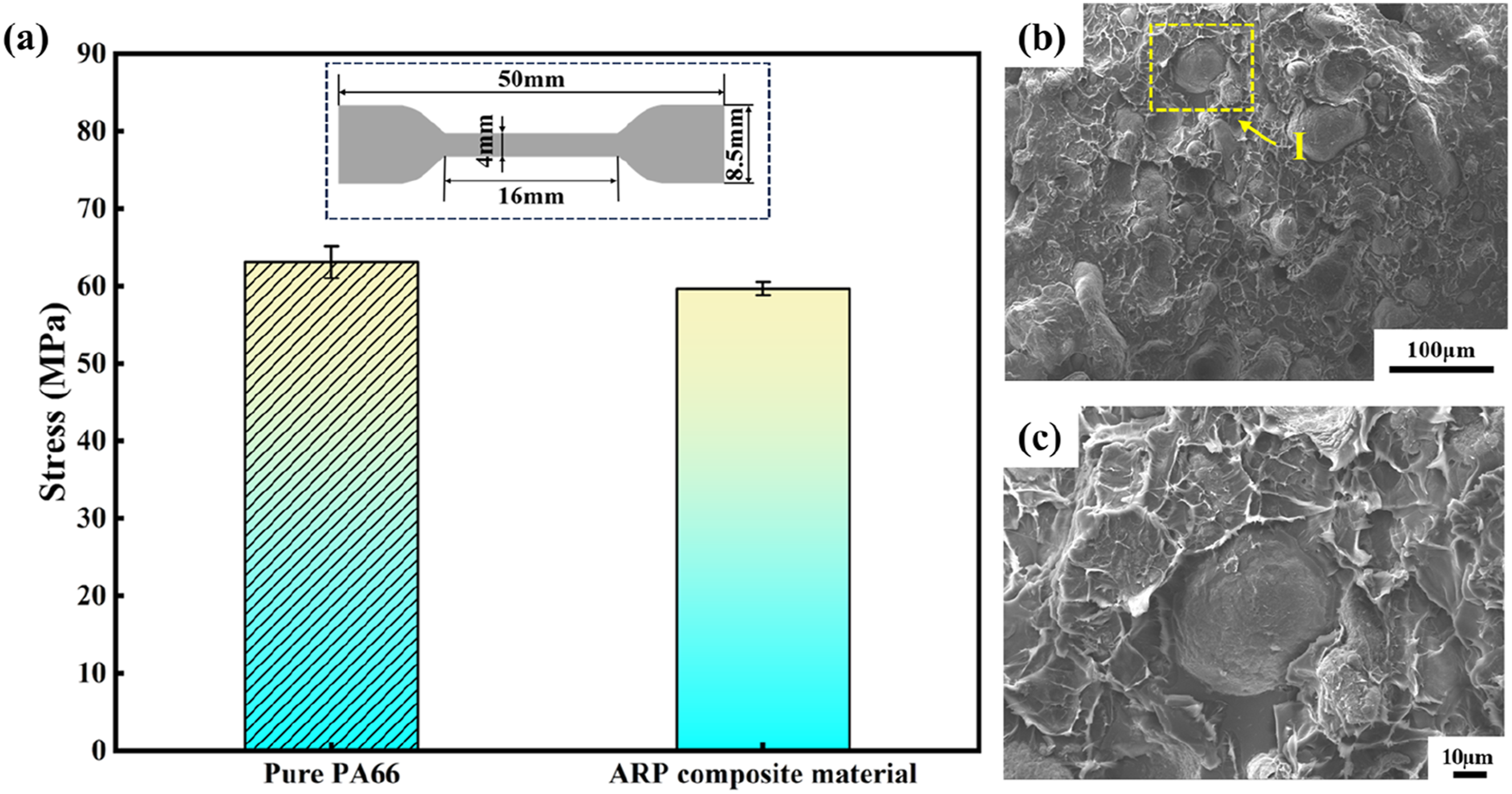
Results and discussion
Properties of the ARP composite
Quasi-static tensile behavior
The tensile test results for pure PA66 and the ARP composite are presented in Figure 3(a). The pure PA66 exhibited an average ultimate tensile strength of 63.1 MPa, whereas the ARP composite reached an average value of 59.7 MPa. In particle-reinforced polymer composites, tensile strength is primarily governed by the molecular chain network of the continuous polymer matrix. As the filler volume fraction increases, the continuity of the matrix is weakened, reducing the number of effective load-bearing chains and consequently decreasing the overall tensile strength. The elastic modulus of PA66 was 197 MPa with an elongation at break of 110.64%. After the addition of aluminum particles, the elastic modulus of the ARP composite increased significantly to 3279 MPa, while the elongation at break decreased to 3.38%, which is consistent with the typical reinforcing effect of metallic particles in polymer matrix composites. The applied electric field played a critical role in modifying the interfacial chemistry between the Al particles and the PA66 matrix. Specifically, hydrolysis of the silane coupling agent generated hydroxyl groups, which subsequently reacted with hydroxyl groups on the Al particle surface through dehydration to form Si-O-Al bonds. The formation of these bonds has been confirmed in the study by Lin et al. 18 In addition, the electric field can further enhance the hydrogen-bonding effect at the interface, thereby strengthening interfacial interactions. The electric field further facilitated this interfacial hydrogen-bonding process, which is consistent with observations reported in the literature. 35
Fractographic analysis of the ARP composite shown in Figure 3(b)-(c) reveals typical ductile fracture features. Minimal plastic deformation was observed in the polymer matrix, whereas the embedded metal particles remained firmly anchored within the plastic matrix, forming a continuous network-like structure. The presence of polymer tear ridges adhering to the particle surfaces provides additional evidence of strong chemical bonding between the metal particles and the molten polymer during processing. This robust interfacial bonding effectively inhibits debonding between the heterogeneous phases and suppresses the initiation of microcracks at the metal-polymer interface.
Fatigue life under cyclic loading
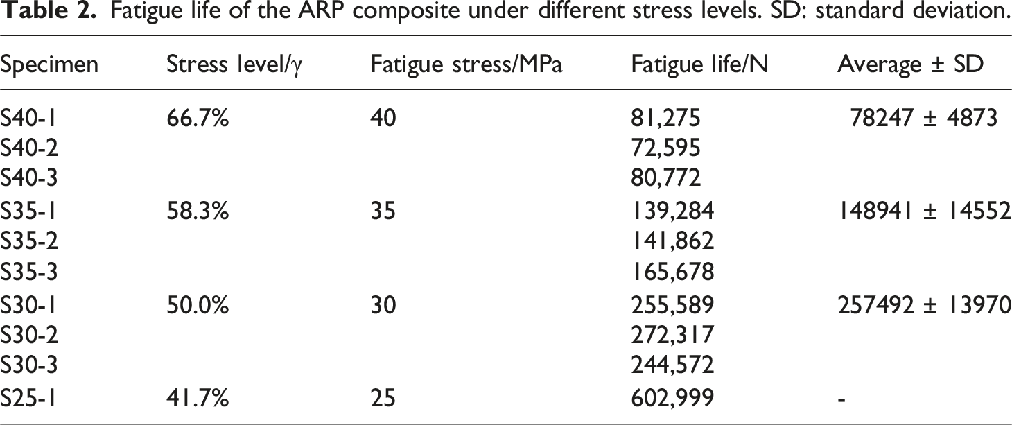
Fatigue life of the ARP composite under different stress levels. SD: standard deviation.
The fatigue data were fitted using the classical Basquin relationship,
24
as expressed in equation (1):

The fatigue life results for the ARP composite are shown in Figure 4. The Basquin model exhibits excellent agreement with the experimental data, yielding a correlation coefficient of 0.9863. This strong correlation indicates that the S-N relationship provides a reliable approximation of the composite’s fatigue life. S-N curve of ARP composite material.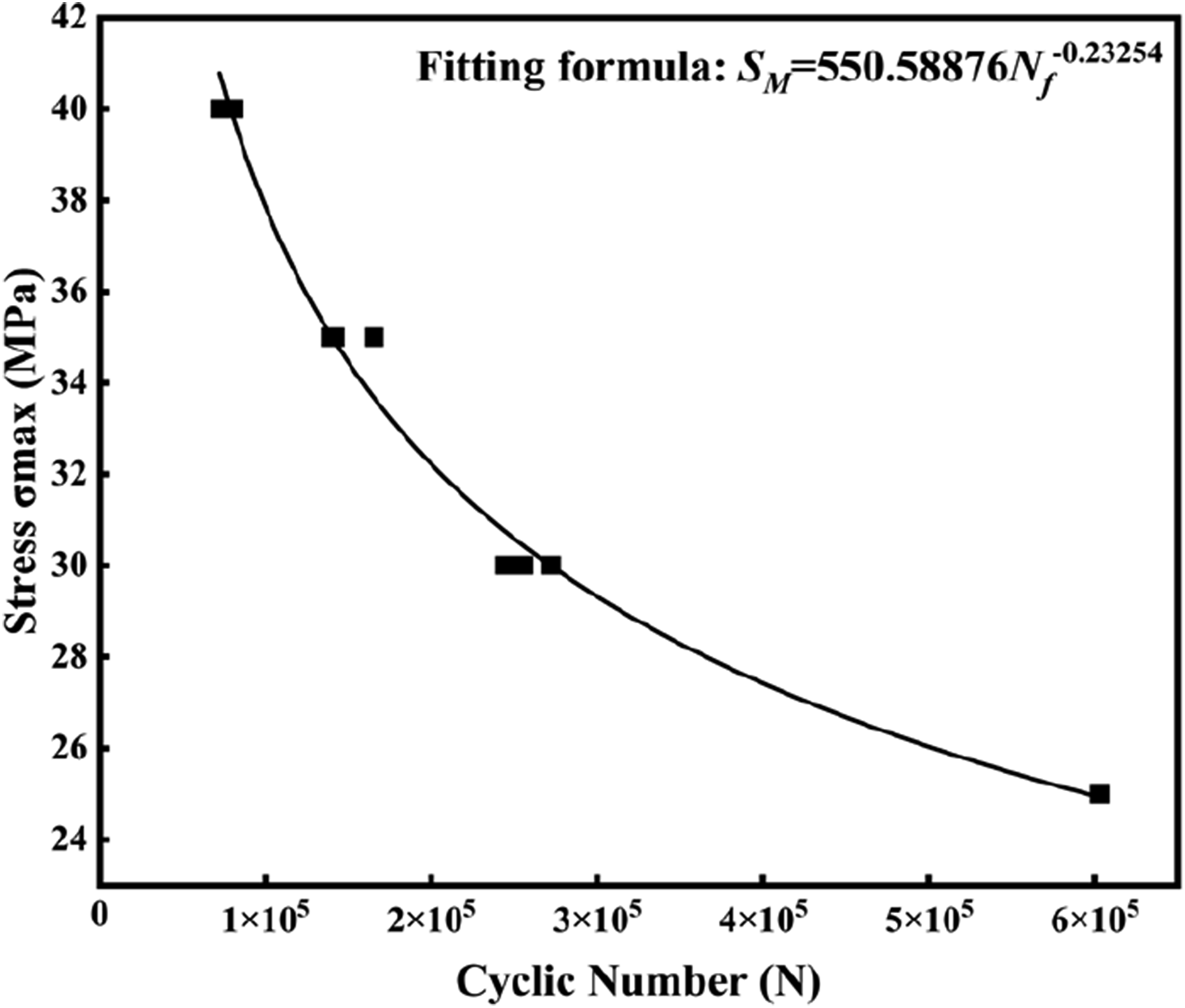
As expected, fatigue life decreases with increasing cyclic stress. When the applied stress is below 30 MPa, the reduction in fatigue life with increasing stress is relatively gradual. However, once the stress exceeds 30 MPa, fatigue life decreases sharply. This transition is attributed to the rate of damage accumulation: at lower stress levels, damage progresses more slowly, resulting in a flatter S-N trend and longer fatigue life, whereas at higher stress amplitudes, damage accelerates significantly and leads to earlier failure. 36
Fatigue deformation and damage evolution
The displacement evolution of the ARP composite under various stress levels is presented in Figure 5(a). Taking the ratcheting response at 25 MPa as an example, the fatigue failure process can be divided into three distinct stages. In the initial stage, the composite begins to sustain cyclic loading, leading to a rapid increase in strain from 0 to 2.84%. During the second stage, the strain grows more gradually, rising from 2.84% to 4.44% as the fatigue process progresses. In the final stage, the strain increases sharply, ultimately resulting in specimen failure. Similar three-stage ratcheting behavior was observed across all applied stress levels, indicating that the majority of the fatigue life is dominated by the initiation and early propagation of microcracks. Cyclic deformation behavior of the ARP composite: (a) ratcheting curves at different stress levels; (b) hysteresis loop at 25 MPa; (c) representative hysteresis loop after 9000 cycles; (d) phase lag between stress and strain after 9000 cycles.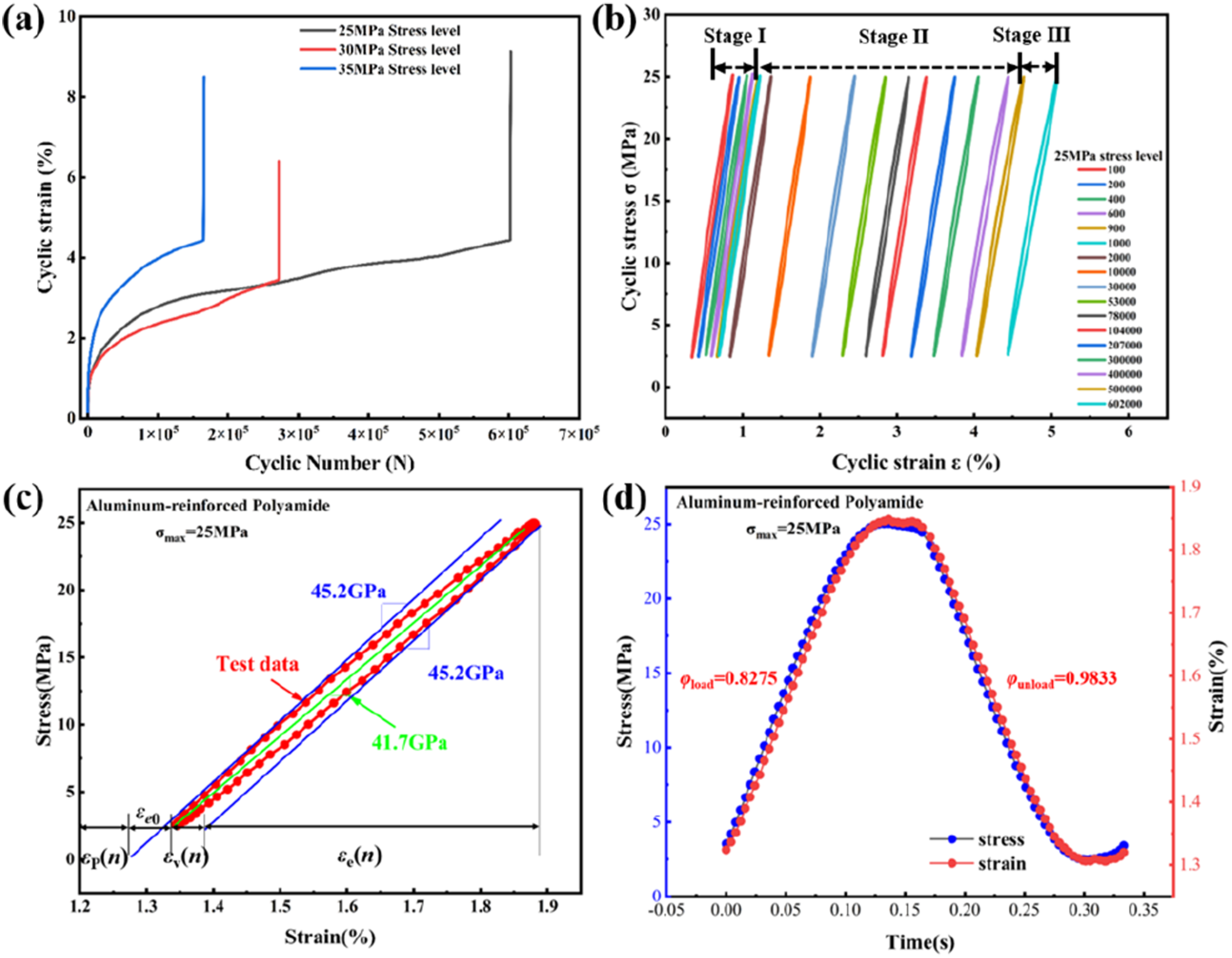
The cyclic deformation characteristics of the composite are shown in Figure 5(b). The hysteresis loops progressively shift to the right during cycling, reflecting the accumulation of plastic strain. At failure, the maximum strain reaches approximately 4.5%. This progressive loop drift can also be categorized into three stages. In the first stage (lifetime <103 cycles), the loop shifts rightward slowly and stabilizes, corresponding to gradual plastic strain accumulation. In the second stage (between 103 and 5 × 10⁵ cycles), the loop undergoes a more pronounced shift before again stabilizing; the loops become increasingly dense, indicating limited ability of the composite to undergo further plastic deformation, thereby leading to accumulated hysteretic strain. In the third stage (around 6 × 10⁵ cycles), an abrupt change in strain occurs, accompanied by catastrophic failure.
The hysteresis loop behavior within a single loading cycle is illustrated in Figure 5(c)-(d). The stress-strain response exhibits a pronounced elliptical hysteresis pattern, where the semi-major axis substantially exceeds the semi-minor axis. This response arises from the heterogeneous nature of the composite, which consists of two phases with markedly different stiffnesses. Under cyclic loading, the effective stiffness decreases, resulting in increased elastic strain. The observed strain lag and loop offset indicate the presence of irreversible residual plastic strain, demonstrating that the deformation consists of both elastic and plastic components. This behavior differs from that of homogeneous isotropic polymer materials, as reported in previous studies. 37
The hysteresis loops obtained after 1000 cycles at different stress levels are presented in Figure 6. The area enclosed by each loop corresponds to the energy dissipated per cycle, which was normalized with respect to the strain amplitude. The calculated energy losses were 1.433, 1.727, and 2.126 for stress levels of 25, 30, and 35 MPa, respectively. As the applied stress increases, the energy dissipation rises from 1.433 to 2.126. Specifically, increasing the stress from 25 to 30 MPa results in a 20.5% increase in energy loss, whereas an increase from 30 to 35 MPa produces a 23.1% rise. (a-c) Hysteresis loops of the ARP composite after 1000 cycles at different stress levels.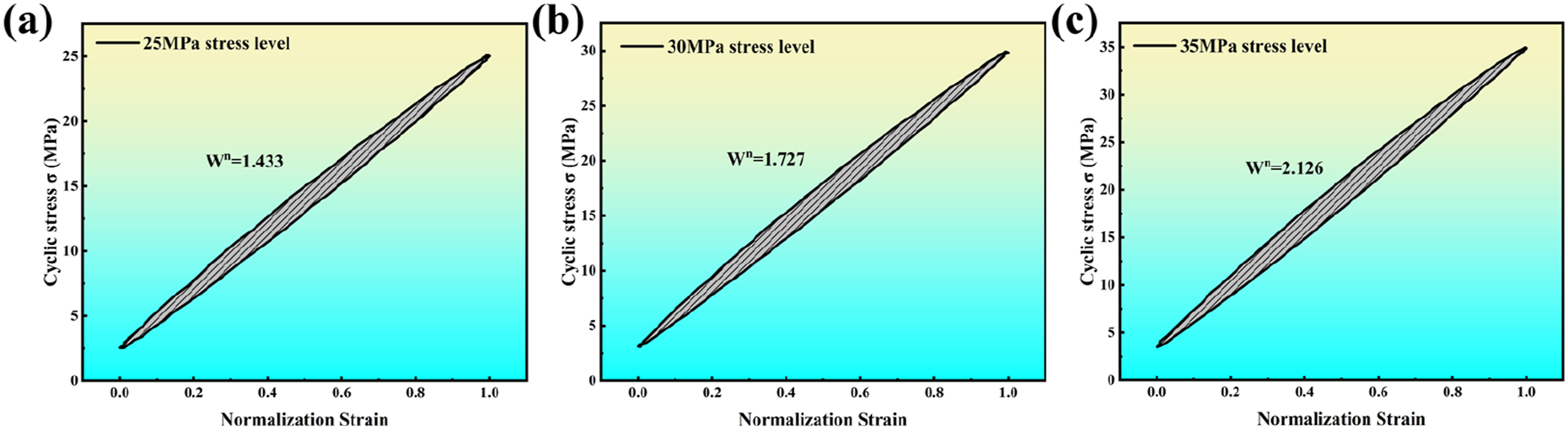
These results demonstrate that higher stress levels significantly amplify the per-cycle energy dissipation of the composite. The increased energy loss indicates more severe damage accumulation within each loading cycle, which in turn accelerates fatigue degradation and leads to a shorter fatigue life.
Fatigue fracture mechanisms
The fatigue fracture surfaces of the ARP composite are presented in Figure 7. Two primary fracture morphologies are observed: ductile fracture and cleavage-like brittle fracture. The crack origin, crack propagation region, and final overload zone are clearly distinguishable. At a cyclic stress of 25 MPa, cracks initiate at the origin and propagate radially outward until reaching the specimen boundary. In contrast, at 35 MPa, the composite undergoes the highest per-cycle energy dissipation and the most severe damage accumulation, resulting in rapid fatigue failure without the development of a well-defined crack initiation zone. (a-c) Fatigue fracture surfaces of the ARP composite under different stress levels.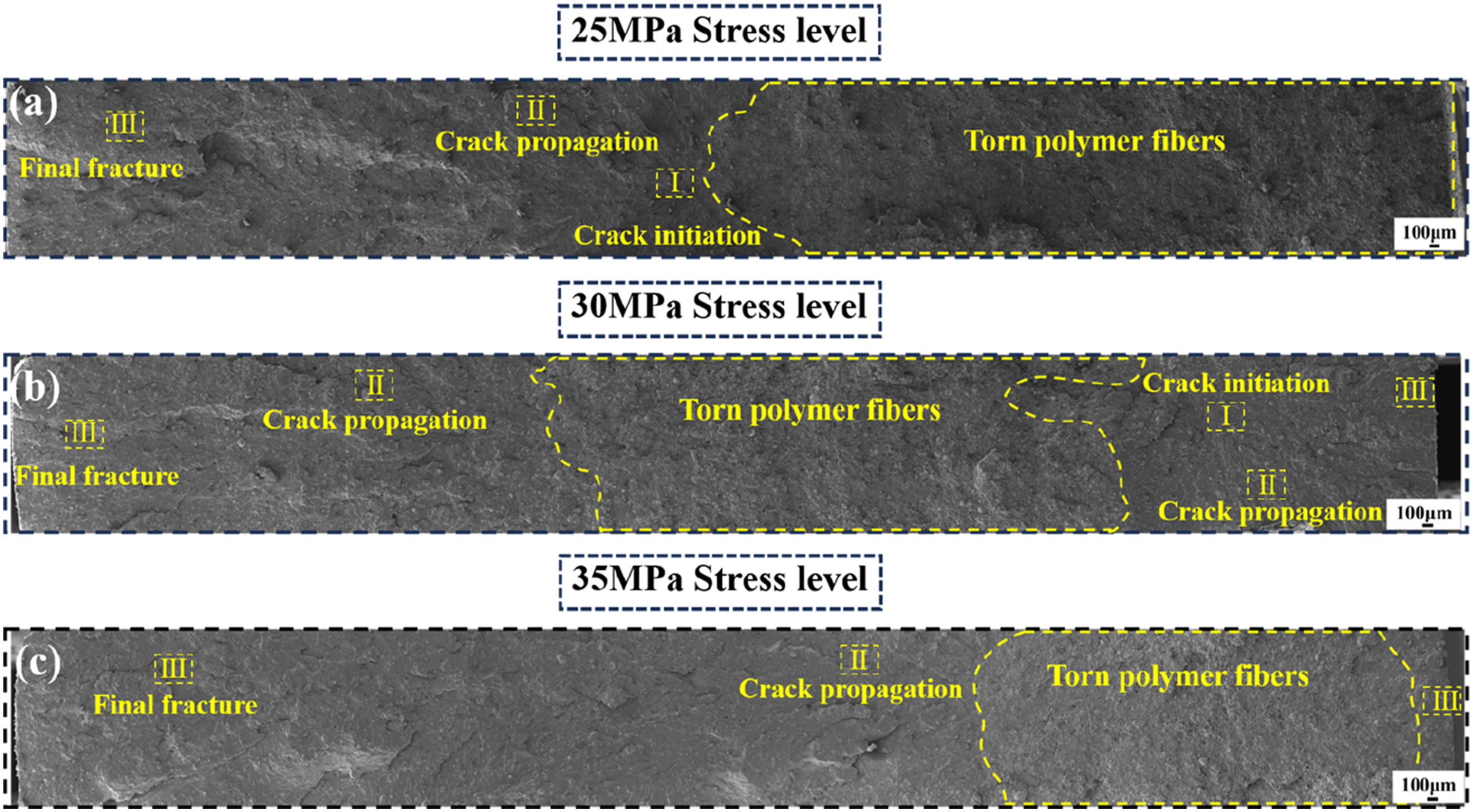
As the applied stress level increases, numerous grooves and pits appear on the fracture surface, reflecting intensified micro-damage processes. During fatigue loading, the maximum applied stress remains constant; therefore, as cracks initiate and propagate, the effective load-bearing area decreases, causing a corresponding increase in the local stress at the crack front. The load-bearing capacity of the material during crack initiation and propagation can be estimated using equation (3).
38
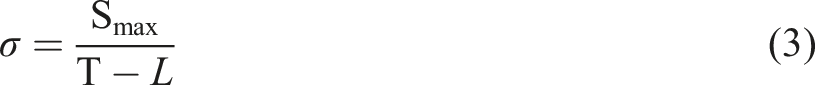
In equation (3), σ represents the load-bearing strength of the material during crack initiation and propagation, Smax denotes the maximum applied stress in the fatigue test, T is the width of the aluminum plate, and L is the crack length measured during fatigue loading. When the load-bearing strength of the composite remains below its yield strength, the resulting fatigue fracture morphology resembles that observed under static tensile loading, exhibiting ductile characteristics. Conversely, when the load-bearing strength exceeds the yield strength, the fracture behavior transitions toward cleavage-like brittle failure.
The area of the irregular ductile fracture features was quantified using ImageJ software, and the ratio of ductile fracture characteristics was calculated by dividing this area by the cross-sectional area of the specimen. At a low cyclic stress of 25 MPa, ductile polymer fracture features accounted for 44.3% of the total fracture surface area. As the applied stress increased to 30 and 35 MPa, this proportion decreased to 33.1% and 27.4%, respectively. This reduction demonstrates that with increasing cyclic stress, the yield strength of the composite is reached at progressively shorter crack propagation lengths. As a result, the relative contribution of ductile fracture diminishes, and cleavage-like features become more prevalent on the fracture surface.
The fatigue fracture morphology of the ARP composite is shown in Figure 8(a), where two distinct fracture patterns-ductile fracture and cleavage-like brittle fracture-can be clearly identified, as illustrated in Figure 8(b)-(c). Due to stress concentration at the specimen edge, cracks initiate from the periphery and propagate toward the center under cyclic loading. When the crack length is relatively short, the load-bearing strength of the composite remains below its yield strength, resulting in polymer tear-edge features characteristic of ductile fracture. During the sintering process, molten polymer encapsulates the aluminum particles; thus, under fatigue tension at lower load-bearing levels, numerous tear ridges form around the particle-matrix interface, as shown in Figure 8(e). This behavior reflects the strong interfacial bonding between the aluminum particles and the PA66 matrix, where the interfacial strength exceeds that of the surrounding polymer, causing the particles to remain firmly embedded. Fatigue fracture surface at a stress level of 25 MPa; (a) overall SEM morphology; (b-e) magnified views of regions I, II, III, and IV, respectively.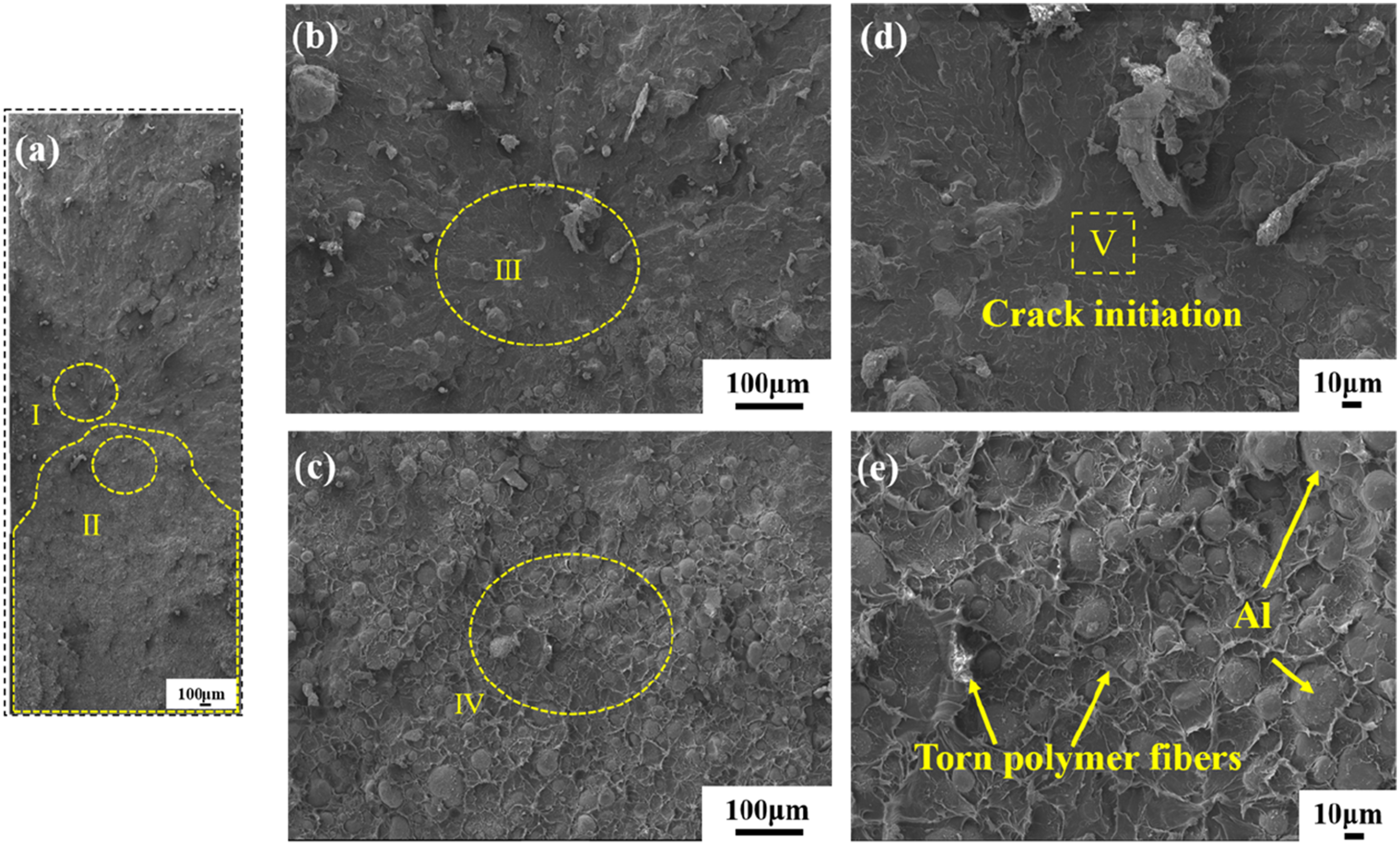
As the crack propagation length increases, the local opening displacement grows, generating higher stress concentration ahead of the crack tip. Once the local load-bearing strength exceeds the material’s yield strength, plastic deformation occurs, promoting the formation of a fatigue crack origin at the particle-matrix interface, as observed in region V of Figure 8(d). From this point, the crack propagates outward, producing river-like features and well-defined crack growth regions until final failure occurs at the specimen edge.
Because the overall fracture of the plate is dominated by polymer tear-edge behavior, load transfer within the composite promotes the predominance of ductile fracture features throughout most of the fatigue process. In contrast, cleavage-like fracture propagates very rapidly and therefore occupies only a small portion of the total fracture surface. As stress levels increase, the area fraction of ductile tear-edge morphology decreases, leading to a corresponding reduction in fatigue life. This fracture evolution is consistent with theoretical expectations regarding the influence of stress amplitude on damage mechanisms and fatigue performance.
Quasi-static behavior of the dissimilar joint
Tensile performance of the joint
The load-displacement response of the dissimilar joint, exhibiting two distinct fracture modes, is presented in Figure 9. When the composite panel thickness was 2 mm, failure occurred through interfacial shear fracture, and the corresponding static load reached 1368.2 N. For lap joints exhibiting shear fracture, the shear strength of the joint was calculated by dividing the maximum lap-shear failure load by the actual fracture area, resulting in a value of 19.58 MPa. As the composite thickness increased to 3.04 mm, failure shifted from the joint interface to the composite substrate, resulting in tensile fracture with a higher static load of 1935.6 N. For lap joints exhibiting tensile fracture, the joint strength was calculated by dividing the maximum lap-shear failure load by the specimen width and the thickness of the lower plate. The resulting tensile strength of the joint was 42.2 MPa, corresponding to a joint efficiency of approximately 70.6%. Compared with the tensile strength of the ARP composite (59.7 MPa), the reduction in strength of the composite near the weld region may be attributed to a decrease in polymer crystallinity and possible molecular weight degradation during the welding thermal cycle. This observation is consistent with the findings reported by Yang et al.
39
These observations indicate that dissimilar joints may exhibit either interfacial shear failure or tensile fracture during tensile loading, depending on the composite thickness. Fracture modes and corresponding loads of the dissimilar joints (tensile rate: 0.5 mm/min; maximum load: 50 kN; tensile strength (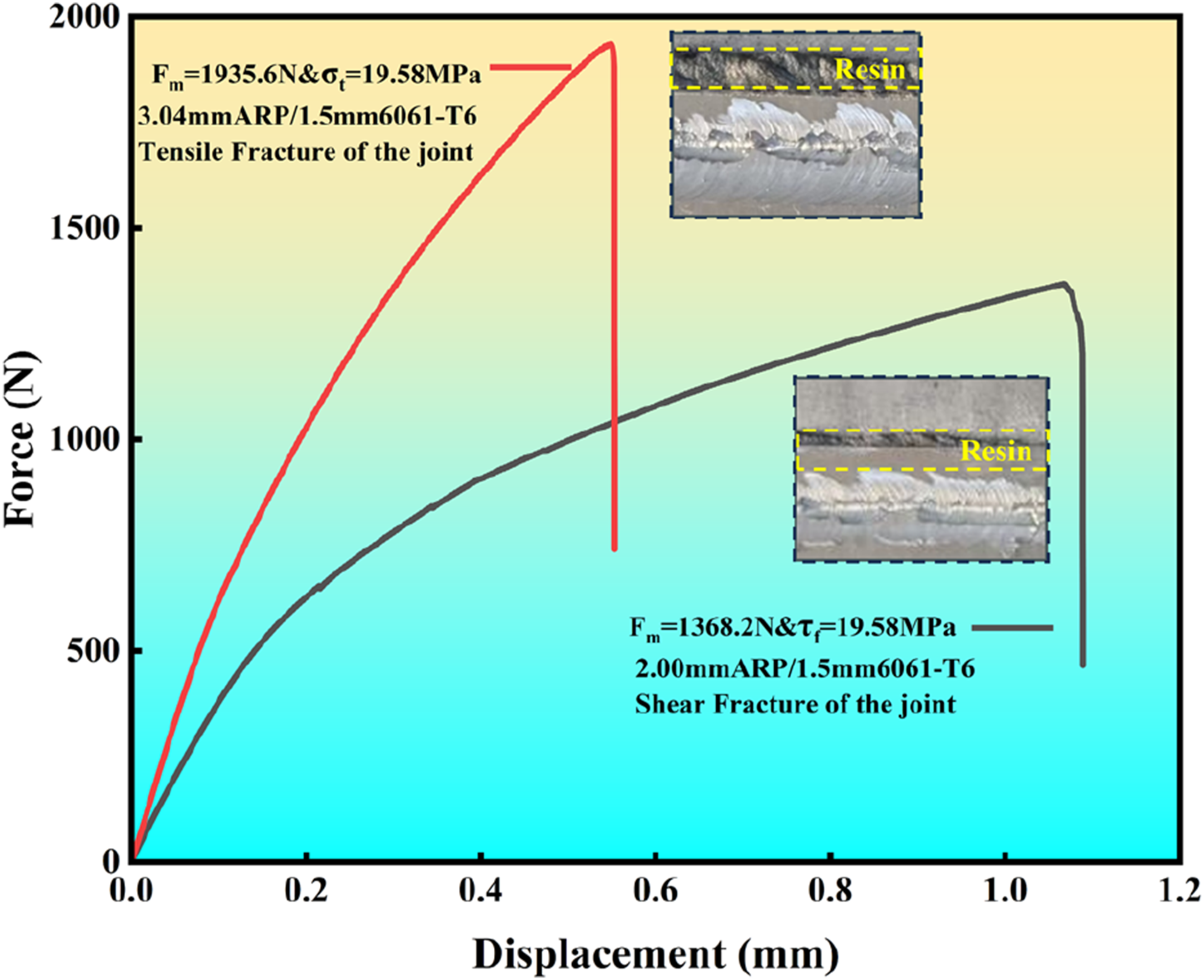
This transition in failure mode is attributed to the thermo-mechanical interactions occurring during friction stir lap welding. Under high rotational speed and specified plunge depth, the rotating tool generates substantial frictional heating and pressure, softening the polymer and causing a portion of the composite material to be extruded from the joint region. As panel thickness increases, a greater volume of softened material is expelled under identical welding parameters, as illustrated in the inset of Figure 9. Owing to the significant thermal property mismatch between the composite and aluminum alloy, voids or gaps readily form in the regions of extruded material during cooling, leading to pronounced stress concentration. The larger the volume of expelled material, the more severe the stress concentration becomes. 40
During tensile loading, the joint fabricated with a 3.04 mm composite panel exhibited a substantial gap at the extruded region. Misalignment between the neutral axes of the metal and composite sheets induced secondary bending moments, promoting crack initiation and propagation through the composite substrate until catastrophic failure. In contrast, when the composite thickness was 2 mm, extrusion-induced defects at the interface were relatively small. The load-bearing capacity of the substrate exceeded that of the interfacial region, leading to shear failure with an interfacial shear strength of 19.58 MPa. This failure mechanism is consistent with the behavior reported by Arménio et al. 41
Interfacial microstructure
The morphology of the FSLW joint is presented in Figure 10. Under the combined influence of frictional heat and forging pressure, the softened aluminum alloy plastically deforms toward the ARP composite, thereby increasing the effective bonding area. Meanwhile, the composite undergoes partial remelting and deformation, and a small amount of molten PA66 matrix is extruded from the weld seam. During this process, numerous aluminum particles within the composite are expelled toward the aluminum alloy surface. Through friction-induced heating, a metallurgically bonded network is likely formed at the dissimilar interface, substantially enhancing the mechanical performance of the joint. Evidence suggesting this metallurgical bonding is shown in Figure 10(b). Interfacial characteristics of the FSLW dissimilar joint: (a) macroscopic view showing aluminum particle bonding on the alloy surface; (b) magnified view of region I; (c-d) results of line scans 1 and 2.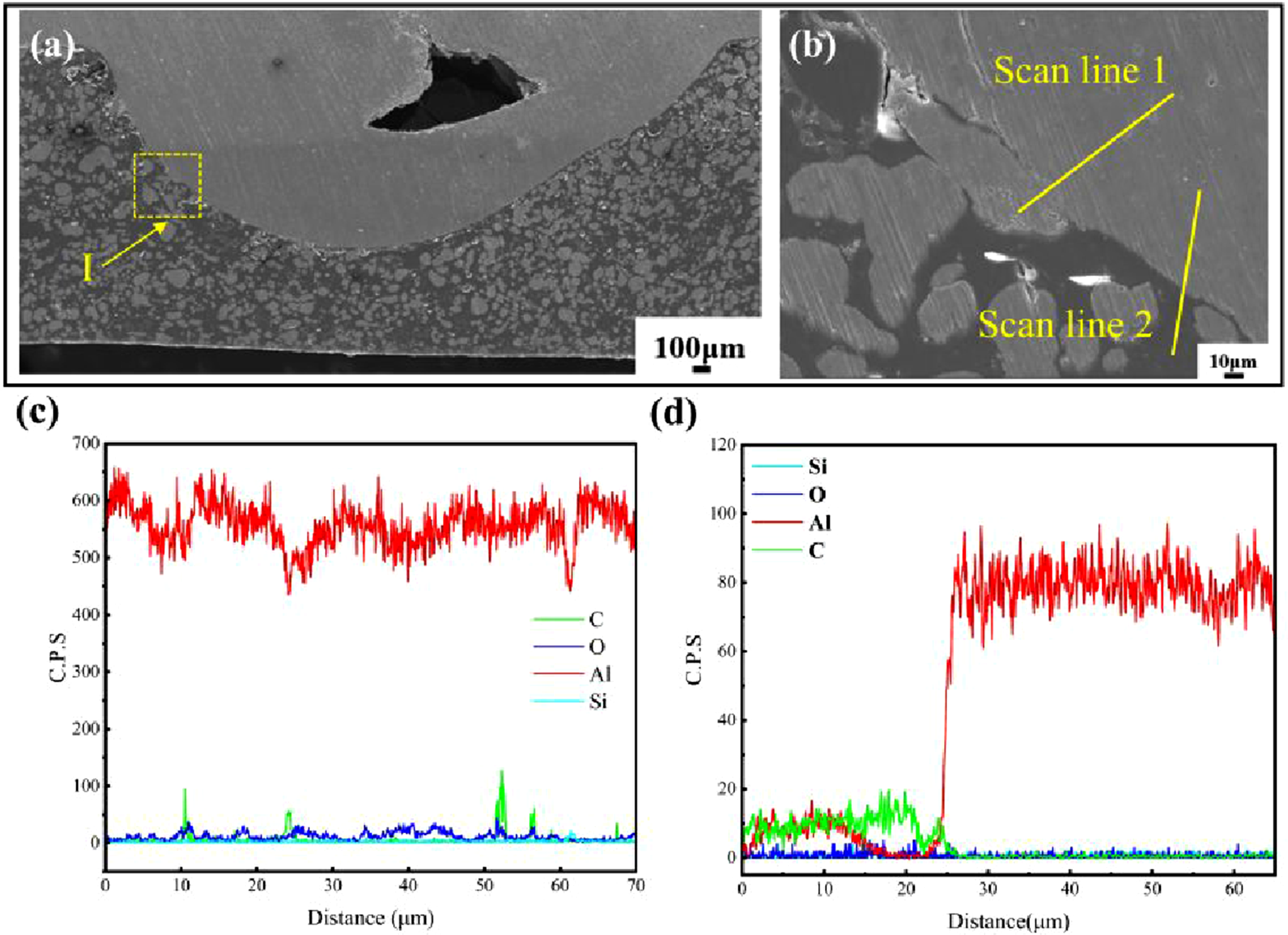
A EDS analysis was conducted across the bonded interface, as shown in Figure 10(c),suggesting the presence of metallurgical bonding between the aluminum particles and the aluminum alloy substrate. Elemental line scans across the heterointerface (Figure 10(d)) reveal a mixed zone containing both C and Al species, indicating intimate interaction between the composite and metal phases. Based on fractographic observations and qualitative discussion of the failure mechanism, it is inferred that during welding, carboxyl groups within the PA66 matrix are likely to react with the surface oxide film of the aluminum alloy, leading to the formation of C-O-Al bonds. This interfacial chemical bonding was subsequently verified through XPS analysis of the shear fracture surface.
Shear fracture morphology
The shear fracture surfaces at various weld locations are shown in Figure 11. A substantial amount of remelted polymer matrix adheres to the 6061-T6 aluminum side, with aluminum particles embedded within the polymer, as illustrated in Figure 11(c). The extensive polymer residue surrounding the aluminum particles originates from the strong chemical bonding formed during the preparation of the ARP composite. Specifically, the coupling agent promotes interfacial reactions between the PA66 matrix and the aluminum particles, and this bonding is further enhanced during sintering under the applied electric field. Shear fracture morphology of the dissimilar joint: (a) 6061-T6 metal side; (b-c) magnified views of regions I and II; (d) ARP composite side; (e-f) magnified views of regions III and IV.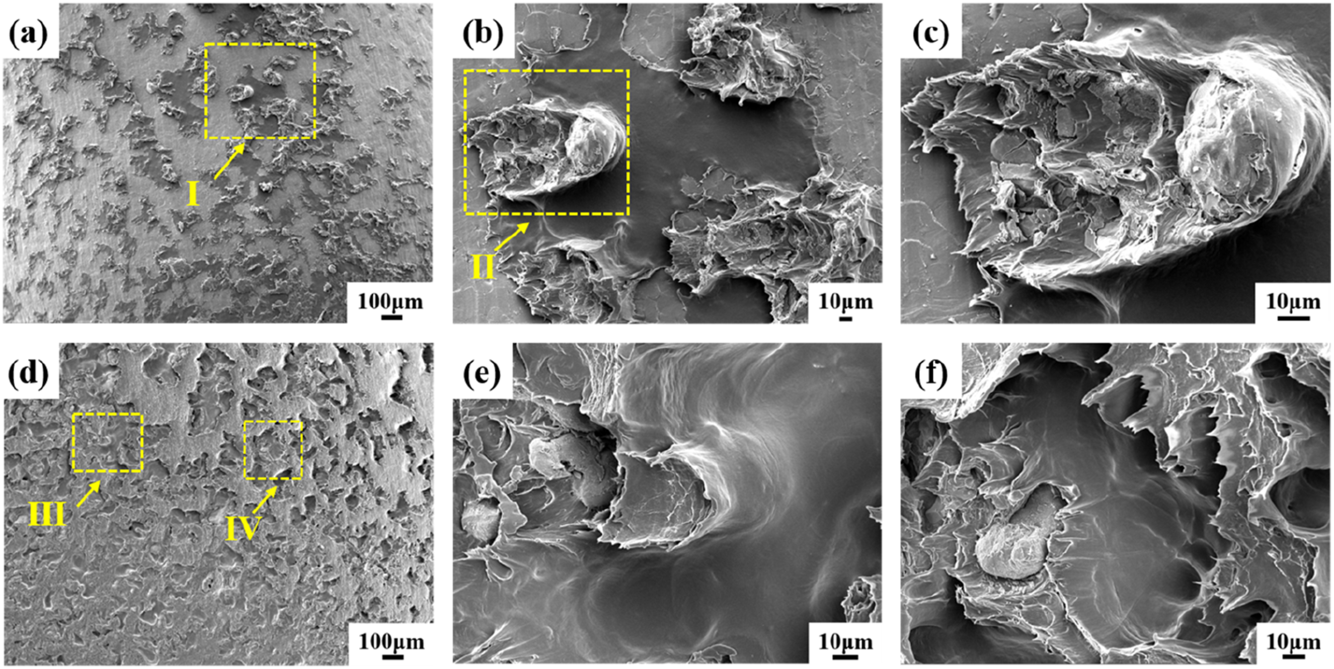
During FSLW, the combined effects of tool-induced frictional heating and compressive deformation soften the composite material, causing aluminum particles to migrate toward the dissimilar interface, where they form metallurgical bonds with the aluminum alloy substrate. Under static tensile loading, the strength of these metallurgical bonds between aluminum-aluminum regions significantly exceeds the adhesive interactions between the aluminum particles and the PA66 matrix. Because the polymer exhibits substantial ductility, it undergoes localized deformation around the aluminum particles, as shown in Figure 11(e), which contributes to the overall plastic deformation capacity of the dissimilar joint.
The metallurgical bonding at the interface enhances the adhesion of softened polymer during welding, promoting more robust chemical interactions at the dissimilar interface. As a result, numerous polymer tear ridges remain adhered to the aluminum alloy surface, while the composite side exhibits extensive porosity, as shown in Figure 11(d). The coexistence of metallurgical bonding and substantial polymer residues indicates the simultaneous development of strong mechanical interlocking and chemical bonding within the joint. These interfacial features provide a mechanistic explanation for the excellent mechanical performance exhibited by the dissimilar FSLW joint.
Interfacial bonding mechanisms
Wu et al. 42 reported that functional groups on polar thermoplastics and surface oxides on metals play a critical role in the high-strength bonding mechanisms of FSLW joints. In the present study, the PA66 matrix in the ARP composite interacts with the native oxide film on the aluminum alloy surface under the combined effects of thermal and mechanical loading during welding. Covalent or ionic bonding may therefore occur at the aluminum-polymer interface. To further verify the formation of new chemical bonds, XPS analysis was conducted on Regions I and II of the dissimilar joint fracture surface. Region I corresponds to polymer residues adhered to the 6061-T6 aluminum surface, whereas Region II represents an exposed 6061-T6 metal surface.
The XPS spectra for Region II reveal trace amounts of polymer-related elements present on the metal surface, as shown in Figure 12(b)-(c), suggesting the existence of nanoscale polymer deposits at this location. These findings imply that interfacial reactions likely occurred during welding, resulting in the formation of chemical bonding between the ARP composite and the aluminum alloy. SEM-EDS analysis of the metal side.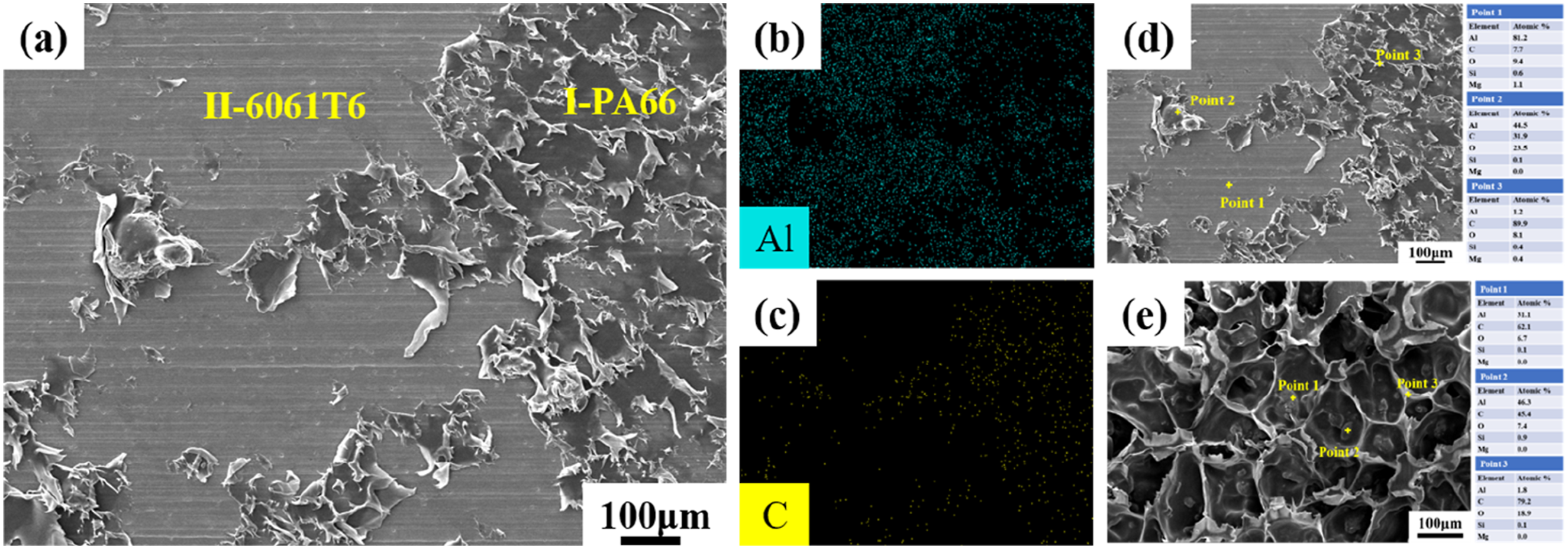
The C 1s core-level spectra for Regions I and II are presented in Figure 13(a) and (d), with the full width at half maximum (FWHM) fixed at 1.3 eV. As shown in Figure 13(b) and (e), no additional chemical bonding is detected in Region II; however, a new peak emerges at 284.42 eV in Region I, indicating the formation of new chemical bonds during the welding process. Based on the interpretations provided by Liu and Wang et al.,43,44 this peak is attributed to the formation of C-O-Al bonds. XPS analysis of the metal side: (a-c) full spectrum, C 1s, and Al 2p peaks for region I; (d-f) corresponding spectra for region II. The new interfacial peak observed in (b-c) is identified as the C-O-Al bond.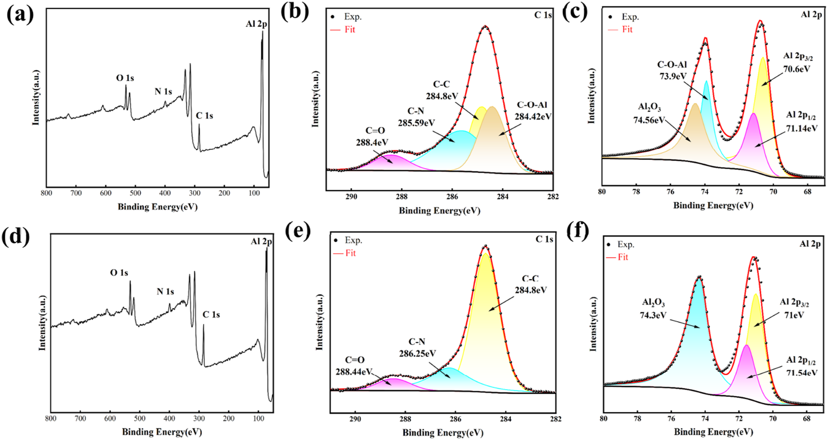
To further substantiate the presence of these newly formed bonds, the Al 2p XPS spectra from Regions I and II are shown in Figure 13(c) and (f). In Region I, besides the expected Al2O3 component at 74.56 eV and the metallic Al 2p1/2 and Al 2p3/2 components at 71.14 eV and 70.6 eV, respectively, an additional peak appears at 73.9 eV. This distinct component suggests the presence of C-O-Al chemical bonding within the polymer residues adhered to the aluminum surface. These findings indicate that interfacial chemical reactions likely occurred during FSLW, contributing to the formation of strong chemical bonding at the dissimilar interface. Since the XPS results may be influenced by factors such as adventitious carbon contamination, variations in surface oxides, and ion sputtering effects, they are considered only as possible evidence for the presence of C-O-Al chemical bonding.
Based on the XPS analysis, the bonding mechanism between the ARP composite and the 6061-T6 aluminum alloy appears to be associated with metallurgical bonding between the Al particles embedded in the composite and the aluminum substrate. At the dissimilar interface, under the combined effects of frictional heat and compressive loading, the C = O group in the PA66 amide may interact with the Al2O3 layer on the aluminum surface, possibly resulting in the formation of C-O-Al bonds. The carbon signal detected at the interface is likely related to the cleavage of the C = O bond within the PA66 amide group during the welding process. As a result, substantial polymer residues remain adhered to the metal surface, which is consistent with the XPS results.
The proposed bonding mechanism between the carbonyl group in PA66 and Al2O3 is schematically illustrated in Figure 14. Overall, interfacial adhesion in the dissimilar joint is suggested to arise from two possible synergistic mechanisms: (i) metallurgical bonding formed between Al particles in the composite and the aluminum alloy, and (ii) chemical bonding generated through interfacial reactions between the PA66 amide groups and the aluminum oxide film. The coexistence of these metallurgical and chemical interactions may contribute to enhanced interfacial strength and improved mechanical performance of the FSLW dissimilar joint. (a) SEM image of the dissimilar joint showing 6061-T6 aluminum/Al particles (dark gray) and PA66 matrix (light gray); (b) schematic of the FSLW interfacial bonding mechanism; (c) bonding-line equation and ball-and-stick model illustrating the formation of C-O-Al bonds between PA66 and Al2O3.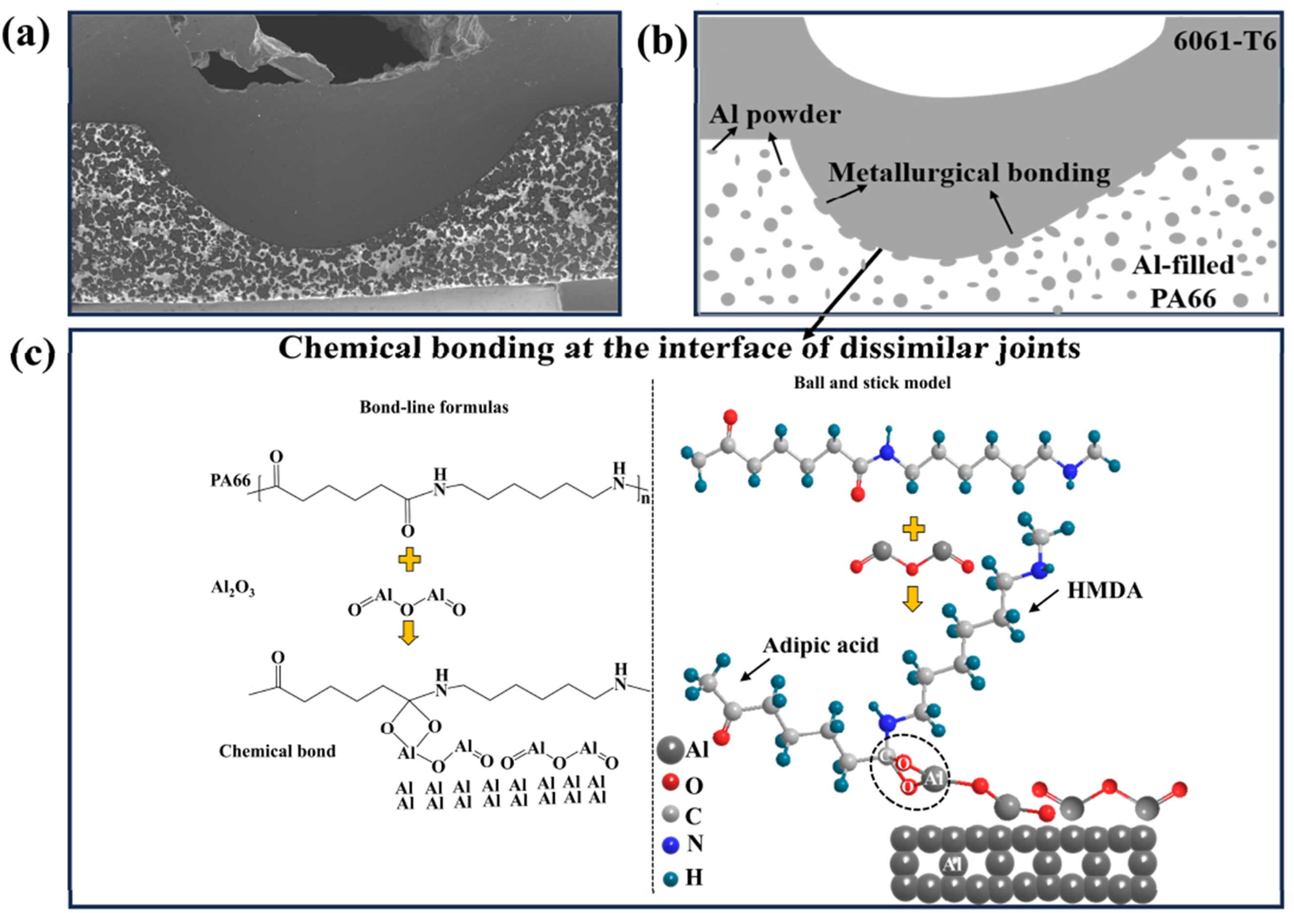
Fatigue performance of the dissimilar joint
Based on the findings presented in the properties of the ARP composite, higher stress levels were shown to induce more severe damage in the ARP composite, leading to a significant reduction in fatigue life. At a stress level of 25 MPa, the composite demonstrated a fatigue life exceeding 600,000 cycles. Therefore, to ensure the feasibility of the dissimilar joint fatigue experiments while maintaining relevance to the material behavior, a lower stress level of 10.5 MPa was selected for the 6061-T6/ARP joint tests. The fatigue loading frequency and stress ratio were kept consistent with those used for the ARP composite specimens to enable direct comparison of the fatigue responses. It should be noted that the fatigue tests in this study were conducted at a single stress level (10.5 MPa) to preliminarily evaluate the fatigue response of the welded joint under cyclic loading. A more comprehensive fatigue characterization involving multiple stress levels will be investigated in future work.
Fatigue life and deformation behavior
The strain evolution of the 6061-T6/ARP dissimilar joint during fatigue loading is presented in Figure 15(a). The strain-life response can be divided into three distinct stages. Stage I corresponds to the crack initiation period at the joint and accounts for only a small fraction of the total fatigue life. During this stage, the strain increases rapidly from 0 to 0.12%. Stage II, which represents the crack propagation phase, occupies the majority of the fatigue lifespan. The strain increases more gradually from 0.12% to 0.18%. Stage III marks the final fracture stage of the joint, wherein the remaining fatigue life is short but the strain rises sharply, ultimately leading to catastrophic failure. Fatigue response of the 6061-T6/ARP welded joint: (a) ratcheting strain evolution; (b) hysteresis loops during cyclic loading; (c) hysteresis loop after 1000 cycles.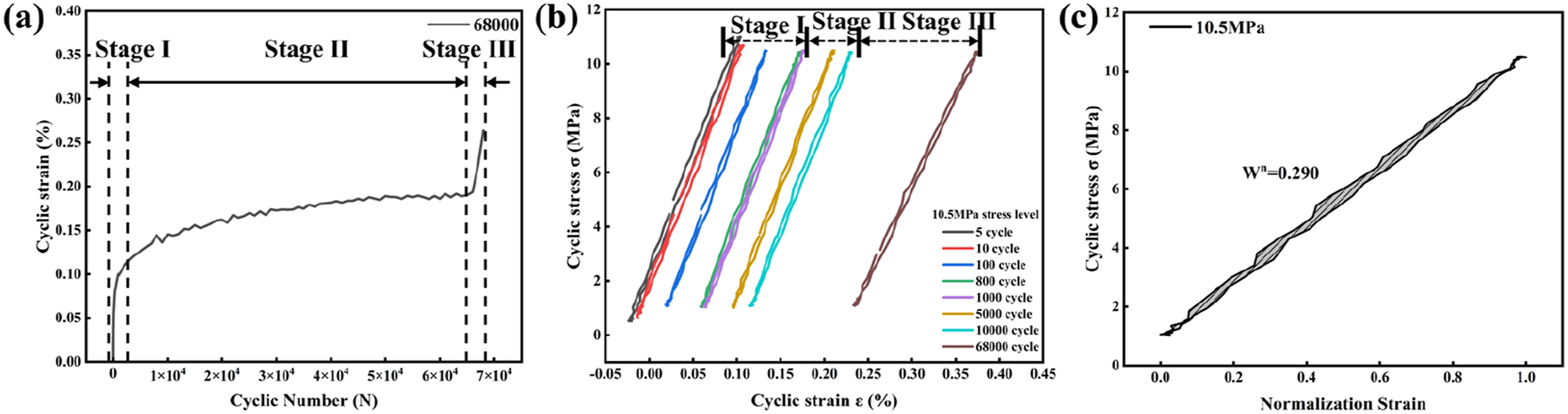
The hysteresis behavior of the joint is shown in Figure 15(b). With increasing cycle count, the displacement amplitude gradually increases, while the slope of the hysteresis loop decreases, indicating progressive stiffness degradation of the joint. The hysteresis loop recorded after 1000 cycles is shown in Figure 15(c). The enclosed area represents the energy dissipated per cycle, which is strongly influenced by the applied stress level. At a stress level of 10.5 MPa, the energy dissipation after 1000 cycles is 0.290, considerably lower than that of the ARP composite alone. This behavior is expected because fracture occurs within the composite layer, meaning the deformation response of the joint is largely governed by the composite material.
However, unlike a homogeneous single-phase material, the dissimilar joint is subjected to non-uniform shear stresses due to its multi-phase nature. As a result, the hysteresis loops exhibit irregularities, complicating the interpretation of fatigue deformation behavior in dissimilar joints. These findings highlight the inherent complexity of evaluating fatigue damage evolution in hybrid material systems. From an engineering application perspective, the fatigue life of approximately 6.8 × 10⁴ cycles obtained at a stress level of 10.5 MPa indicates that the welded joint possesses a certain fatigue load-bearing capacity under cyclic loading. However, compared with the results reported by Correia et al., 45 where the AA6082-T6/Noryl GFN2 joint achieved a fatigue life of 104 cycles under stress levels below 20 MPa, the fatigue life obtained in the present study still has room for improvement. The significant mismatch in mechanical properties between metallic and polymeric materials may lead to stress concentration in the interfacial region, thereby adversely affecting the fatigue performance of the joint. In addition, the quality of interfacial bonding and the presence of potential microstructural defects may also serve as initiation sites for fatigue cracks. Future work may further improve the fatigue performance of the joint by optimizing welding parameters and improving the interfacial structure.
Fatigue failure modes and mechanisms
The fatigue fracture morphology of the dissimilar joint is presented in Figure 16. Fracture occurred at the weld center, where the composite layer was thinnest due to the downward forging pressure applied by the rotating tool. The uneven lower fracture surface shown in Figure 16(a) corresponds to the flow traces left by softened aluminum alloy extruded during FSLW. Because the metallurgical bonding at the shear plane, together with the interfacial chemical bonding, exceeds the intrinsic bonding strength of the composite material, failure occurred through butt fracture within the composite rather than at the dissimilar interface. This suggests that the interfacial bonding strength exceeds the intrinsic strength of the composite, and consequently the fatigue behavior is mainly controlled by damage occurring within the composite material. (a) Fatigue failure mode of the dissimilar welded joint under a stress level of 10.5 MPa; (b-d) magnified views of regions I-III, respectively.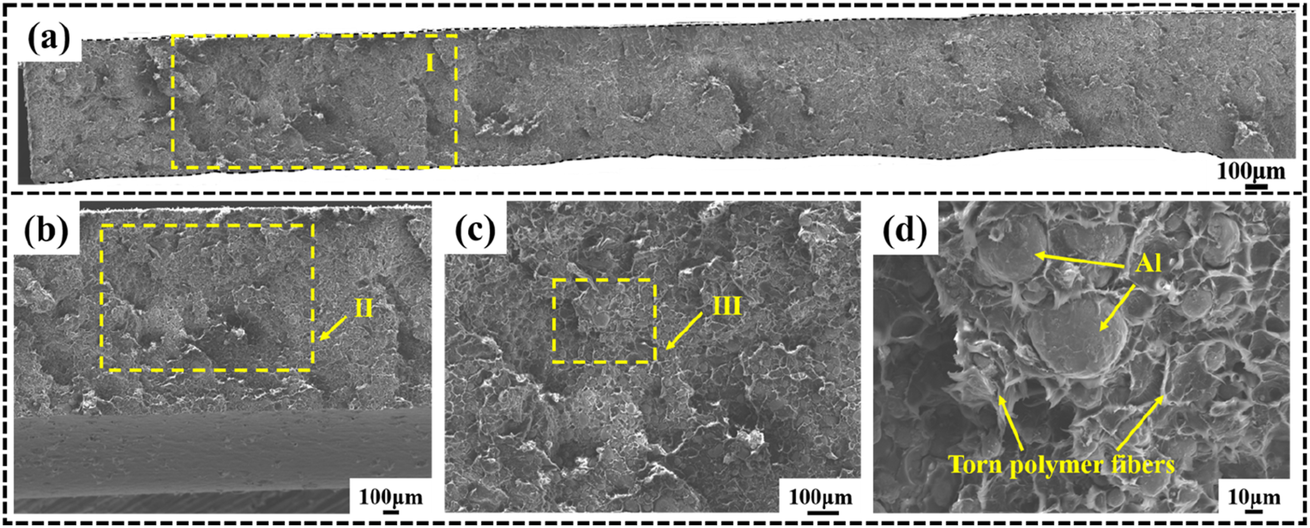
Under the relatively low cyclic loading applied in this study, damage accumulation within the composite was limited. The load-bearing strength of the joint remained below the yield strength of the composite, resulting in a predominantly ductile fracture morphology, as shown in Figure 16(d). The presence of abundant polymer tear edges across the fracture surface indicates significant stress transfer within the composite layer and the absence of major interfacial defects. This behavior contributes positively to the fatigue performance of the dissimilar joint.
The service life of the joint is therefore inherently governed by the fatigue resistance of the composite material itself. Improving the fatigue performance of dissimilar joints will require enhancing the mechanical properties of the composite phase. Future efforts may incorporate reinforcing phases such as carbon fibers or carbon nanotubes to strengthen the composite matrix, thereby increasing its load-bearing capacity and extending the fatigue life of friction stir-welded metal-polymer joints.
Conclusions
The ARP composite developed in this study forms a network structure under the application of an external electric field. Following FSLW with 6061-T6 aluminum, a metallurgically bonded particle-matrix network is established at the dissimilar interface, significantly enhancing joint performance. Based on quasi-static tensile testing, fatigue evaluation, and microstructural characterization, the following conclusions can be drawn: (1) A composite material containing 50 wt.% Al particles was successfully fabricated using an electric field-assisted FAPAS sintering process. The resulting ARP composite exhibited a tensile strength of 59-62 MPa, corresponding to more than 90% of the strength of pure PA66. (2) The fatigue behavior of the ARP composite was highly sensitive to the applied stress amplitude. With increasing cyclic stress, the fatigue life of the material decreased significantly, while the proportion of ductile tearing features on the fracture surface gradually decreased and cleavage-like features became more pronounced. These observations indicate that damage evolution within the material was accelerated under higher loading conditions. (3) The FSLW 6061-T6/ARP joint exhibited a high static load capacity, and microstructural analysis revealed intimate interaction between the aluminum alloy and Al particles within the composite near the interface. Fractographic observations and XPS analysis suggested the possible formation of C-O-Al chemical interactions, which, together with the particle-matrix network structure, contributed to the mechanical integrity of the dissimilar joint. (4) Fatigue testing of the welded joint at a cyclic stress of 10.5 MPa yielded a fatigue life on the order of 6.8 × 10⁴ cycles. Fatigue fracture consistently occurred in the locally thinned composite region beneath the stirring pin, indicating that the fatigue performance of the joint was governed by the structural geometry and local stress concentration rather than interfacial failure. (5) It should be noted that the present study evaluated fatigue behavior at a single stress level, and the statistical dataset and control comparisons remain limited. Therefore, the results provide a preliminary assessment of the fatigue performance of the metal-polymer joint rather than a complete fatigue characterization. Future work will focus on establishing S-N relationships, increasing statistical sampling, and benchmarking the fatigue performance against other joining techniques.
Supplemental material
Supplemental Material - Fatigue behavior and interfacial bonding mechanisms of high-aluminum-content PA66 composites and 6061-T6 by friction stir lap welding
Supplemental Material for Fatigue behavior and interfacial bonding mechanisms of high-aluminum-content PA66 composites and 6061-T6 by friction stir lap welding by Zhenyang Qi, Jianxiang Lin, Shiqiang Yan, Kezhang Zhang, Wenhao Fan, Qiang Zhang, Shaoping Chen in Journal of Thermoplastic Composite Materials
Footnotes
Declaration of conflicting interests
The authors declared no potential conflicts of interest with respect to the research, authorship, and/or publication of this article.
Funding
The authors disclosed receipt of the following financial support for the research, authorship, and/or publication of this article: National Natural Science Foundation of China (52202277, 52375368) and Shanxi Scholarship Council of China (2023-083, 2024-031, 2024-053).
Supplemental material
Supplemental material for this article is available online.