
Abstract
In the field of aerospace engineering, there is a gradual increase in the utilization of FMLs. This study experimentally assessed the influence of varying graphene nanoparticle (GNP) contents (0 wt.% to 1.5 wt.%) on the impact response of carbon fiber reinforced PEEK-Ti fiber metal laminates (CF/PEEK-Ti FMLs). The damage modes and structural integrity of CF/PEEK-Ti under impact response were also investigated by finite element simulation. The findings revealed that FMLs incorporating 0.5 wt.% GNPs exhibited superior impact resistance, with an increase in absorbed energy and impact strength by 23.8% and 25%, respectively, in comparison to FMLs without the addition of GNPs. Furthermore, finite element simulations demonstrate over 98% agreement with experimental data, confirming high model accuracy. Post-impact damage mechanisms in FMLs were simulated via FEM, demonstrating that strategic GNP integration significantly mitigates delamination and matrix crack propagation under impact loading.
Introduction
At the current stage of engineering, carbon fiber composites and their fabrication process are becoming increasingly prevalent as the industry continues to advance.1–3 The composites are distinguished by their high specific strength, high specific modulus, robust resistance to crack expansion, and commendable corrosion and fatigue resistance.4–7 Consequently, they are 6 extensively utilized in marine, automotive, acrospace and other domains.8–11 In aerospace applications, the use of composite materials is increasing, primarily due to their exceptional properties.12,13 With ongoing research, Fiber Metal Laminates (FMLs) have gained popularity and evolved into several variants. FMLs consist of fiber composites and metal layers bonded under specific temperature and pressure conditions, combining the strengths of both materials. They exhibit high specific strength, modulus, impact strength, and fatigue strength.14–16 Therefore, FMLs are used in engineering applications as a substitute for composites with insufficient impact resistance.
During the previous decade, significant interest has been observed in various types of FMLs. The first proposed type was an aramid-reinforced aluminum laminate (ARALL). Subsequently, carbon fiber, glass fiber-reinforced aluminum laminates (CARALL, GLARE) and glass fiber-reinforced titanium laminates (Ti/GFRP) were developed.17–22 However, the GLARE laminate proved unable to withstand high temperatures due to the inherent limitations of epoxy resins and glass fibers in resisting elevated temperatures. Consequently, There is an increasing demand for research into a new generation of carbon fiber-reinforced titanium laminates, which are composed of a high-temperature-resistant polyether ether ketone (PEEK) or polyimide (PE) matrix. There are promising developments in the field of aerospace, with particular relevance to hypersonic fighter aircraft, surrounding the potential for the advancement of carbon fiber-reinforced titanium alloy laminates.
As a result, extensive research has explored the impact resistance properties of carbon fiber-reinforced titanium laminates. For example, Asaee et al. 23 conducted low-speed impact tests on 3D glass fiber fabric reinforced magnesium alloy laminates, and found that 3D fiber fabrics exhibited excellent impact absorption compared to conventional biaxial woven fabrics. However, the impact strength was not as robust as that of the conventional biaxial woven fabrics. Suresh Kumar et al. 24 incorporated Ti/GFRP laminates with Boron Carbide (B4C) and conducted high-velocity ballistic impact tests on them. The findings indicated that Ti/GFRP laminates with 5 wt.% B4C exhibited augmented ballistic resistance. However, FMLs with 10 wt.% B4C demonstrated diminished ballistic resistance due to the agglomeration of the B4C. Sarasini et al. 25 conducted high-velocity ballistic impact tests on polypropylene (PP) based TFMLs reinforced by aluminum alloys and basaltic fibers at varying temperatures. The experimental results demonstrate that basalt TFML exhibits superior performance in comparison to aluminum plate, basalt/epoxy TFML, and glass TFML. Furthermore, the impact performance was enhanced by 42%, 34% and 8% at −40°C. Zheng-Qiang Cheng et al. 26 delved deeply into the impact performance of glass fiber-reinforced aluminum laminates (FMLs), specifically investigating the roles of fiber stacking order and structural configuration. Results indicated that stacking order governed impact behavior in the 2/1 structure FMLs but was inconsequential for the 3/2 structure FMLs. Critically, FMLs with the 3/2 structure displayed substantially higher impact resistance than those with the 2/1 structure.
Nonetheless, the suboptimal functionality of the interfacial mechanical connection of FMLs has prompted researchers to consider potential avenues for enhancement. The interface between the metal and fiber represents the weakest region of the entire structure. Fiber‐metal laminates (FMLs) frequently suffer localized damage in the form of matrix microcracks and interfacial delamination. The mechanical performance of the entire laminate is largely controlled by the intrinsic properties of the polymer matrix. One way to strengthen the interface between metal and composite layers is to modify the metal surface—creating a roughened topology that improves mechanical interlocking with the resin. 27 Alternatively, dispersing nanofillers within the matrix can increase its stiffness and toughness, thereby enhancing the interlayer adhesion and reducing the propensity for delamination. As an illustration, the processes of sandblasting and anodizing can augment the surface roughness of the metal. The incorporation of nanomaterials, including carbon nanotubes (CNTs), SiO2, and graphene (GNPs), into the resin matrix can enhance the mechanical properties of the matrix and the bonding at the metal/matrix/fiber interfaces. This results in an overall improvement in the mechanical properties of the FMLs. The flexural response of basalt-epoxy laminates was analyzed by Yaghoobi et al. 28 with the addition of GNPs, and the results demonstrated that laminates with 0.25 wt.% GNPs exhibited the highest flexural capacity. In a study conducted by Wang Hao et al., 29 MWCNTs were added to Ti/carbon fiber-reinforced polyimide laminates without using diameters to investigate the interfacial bonding properties. The results demonstrated that the average MWCNT diameter was 8 nm, which was comparable to the average MWCNT diameter of 8 nm. The interfacial fracture energy, which serves as an indicator of interfacial mechanical properties, exhibited an increase of nearly 180% in comparison to the material devoid of MWCNTs. Zhang et al. 30 employed ZnO@PPENK in the interlayer of carbon fiber reinforced PPEK laminates (CF/PPEK) in the sandwich. The experimental results demonstrated a 43% increase in interlaminar fracture toughness. Furthermore, the addition of ZnO nanowires resulted in an increase of 112% in the interlaminar fracture toughness.
Graphene nanosheets consist of small sections of graphene produced by exfoliating or precisely slicing at the nanometer scale, and they typically form a single atomic layer of carbon. Since its discovery, graphene has shown immense promise across diverse applications due to its outstanding mechanical characteristics. Moreover, incorporating graphene nanoparticles into PEEK has been proven to improve the composite’s interfacial bonding strength. Papageorgiou et al. 31 prepared PEEK nanocomposites reinforced with either GNPs alone or graphene/short carbon fiber hybrid fillers. Comparative rheological analyses revealed increasing melt viscosity scaling with GNP content in both systems. The study further documented enhanced stiffness and elevated energy storage moduli in GNP-modified PEEK and its hybrid composite counterpart. Cao et al. 32 added different contents of graphene to FMLs and performed bending and shear experiments on them. The incorporation of a specific quantity of graphene was observed to enhance the flexural and shear strength of FMLs. In addition, molecular dynamics (MD) simulations were carried out to investigate the role of GNPs in FMLs, showing that incorporating GNPs increases interfacial energy and thereby enhances the mechanical properties. Arif et al. 33 conducted a comparative study on PEEK composites produced by additive manufacturing, examining how carbon nanotubes (CNTs) and graphene nanoplatelets (GNPs) affect their thermal and mechanical behavior. They found that PEEK reinforced with GNPs showed a lower coefficient of thermal expansion than its CNT‐reinforced counterpart. Furthermore, when 5 wt.% GNPs were introduced into PEEK, Young’s modulus rose by about 23% and the storage modulus increased by roughly 72%. These results indicate that incorporating GNPs as fillers not only reduces PEEK (or PEEK‐CF) thermal expansion but also substantially enhances its elasticity and viscoelastic response. Toraman et al. 34 employed molecular dynamics and density flooding theories to examine the impact of PEEK at the interface of GNP and carbon nanotubes. Their findings revealed that the interfacial energy absorbed by the GNP-PEEK was significantly higher than that absorbed by CNTs. However, the adsorption energy decreased with increasing temperature. Jiang et al. 35 employed GNPs to augment PEEK for utilization in bone restoration. The experimental outcomes demonstrated that GNPs markedly enhance the ductility and toughness of PEEK materials. The 5% GNPs-PEEK composite exhibited the highest bioactivity.
Although the interfacial bonding and mechanical enhancement of graphene nanoplates (GNPs) in composite laminates have been exhaustively documented, literature specifically addressing high-performance thermoplastic fiber-reinforced metal laminates (e.g., CF/PEEK-Ti FMLs) remains limited. Existing studies have predominantly focused on the quasi-static behavior of aluminum-based FMLs, leaving a critical knowledge gap regarding the dynamic impact response and the specific toughening mechanisms within titanium-based thermoplastic systems. In order to address this knowledge gap, the present study systematically investigates the experimental and numerical impact behaviors of CF/PEEK-Ti FMLs reinforced with varying GNP mass fractions (0.25–1.5 wt.%). The distinguishing feature of this work is the elucidation of the synergistic interaction between GNPs and the PEEK matrix at the titanium-polymer interface under dynamic Charpy impact loading. Furthermore, a nonlinear numerical framework integrating Cohesive Zone Models (CZM) was developed to decouple the specific contributions of GNPs to interlaminar toughening versus intralaminar damage mitigation. These findings not only identify the optimal GNP content for impact resistance but also provide a robust predictive tool for the damage tolerance evaluation of next-generation aerospace thermoplastic FMLs.
Experiment details
Materials
The test specimen of the FML was produced by stacking two TC4 titanium alloy sheets, each 0.5 mm thick. A bidirectional T300-3K woven carbon fiber fabric (density: 1.76 g/cm3) from TORAY INDUSTRIES was placed between these metal layers. Polyether ether ketone (PEEK) powders, with an average diameter of 0.25 μm, were supplied by Jilin Province Zhongyan Polymer Materials Co., Ltd. The graphene additives were sourced from Qingdao Maiwei Graphene Equipment Technology Co., Ltd, China.
The preparation of GNPs/PEEK matrix
Predetermined GNP loadings (0.25–1.5 wt.%) were dispersed in acetone via bath sonication (30°C, 150 min) to achieve homogeneous graphene distribution. PEEK particles at corresponding mass fractions were then introduced, followed by 60-min ultrasonication for uniform hybridization. The PEEK/GNPs/acetone suspension was oven-dried at 80°C to evaporate solvent, then manually agitated for 3 min to form GNPs/PEEK composites. Residual moisture was eliminated through 180-min thermal treatment at 150°C. This fabrication protocol is schematized in Figure 1(a). CF/PEEK-Ti material preparation process and hot press curve (a) preparation of GNPs/PEEK matrix (b) surface treatment of TC4 titanium alloy (c) manual paste molding technique (d) hot-press curve.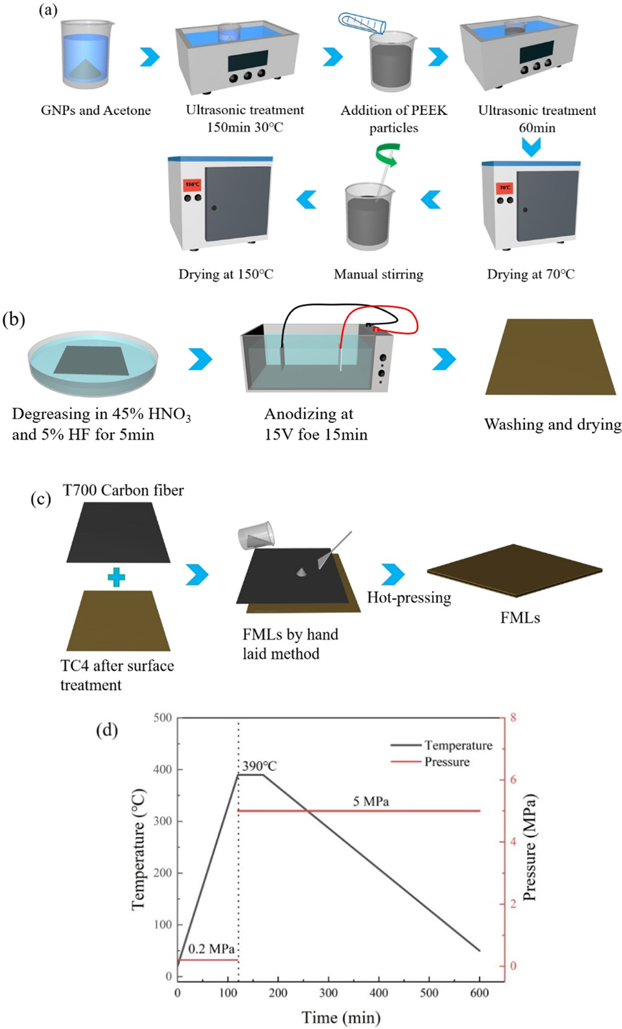
Surface treatment of TC4 titanium alloy
The titanium alloy was subjected to a surface treatment in order to facilitate the attachment of PEEK. As illustrated in Figure 1(b), the surface treatment of TC4 titanium alloy is as follows: The TC4 sample was subjected to a 5-min immersion in a solution comprising 45% nitric acid and 5% hydrofluoric acid. Anodic oxidation of the TC4 was then carried out for a further 15 min using a DC power supply with a voltage of 15 V. The TC4 was connected to an anode, while the cathode was comprised of graphite, with a distance of three cm between the two electrodes. The electrolyte utilized was a 300 g/L sodium hydroxide, 65 g/L sodium tartrate, 30 g/L ethylenediaminetetraacetic acid (EDTA), and 6 g/L Na2SiO3 solution, designated NaTESi.
Preparation of CF/PEEK-Ti fiber metal laminates
In Figure 1(c) the samples were prepared using a 2/1 structure with a lay-up sequence of Ti/[0/90]s/Ti by a hot press molding process. The hot‐press curing procedure consisted of three main steps. First, the assembly was heated from ambient temperature up to 390°C while being subjected to 0.2 MPa of pressure. Next, the temperature was held steady at 390°C for 30 min, with the pressure raised to 5 MPa. Finally, the sample was allowed to cool back to room temperature while maintaining the 5 MPa pressure. The resulting hot press curing curve is presented in Figure 1(d). The dimensions of the cured laminate were 90 × 70 × 1.5 mm. The laminate was then cut into standard specimen sizes using a waterjet cutter.
Characterizations
Microscopic analysis
Fractographic features of tested specimens were characterized by scanning electron microscopy (SU8020 SEM, Japan). Complementary optical microscopy analysis was performed on post-impact fracture surfaces.
Pendulum impact test
The specimen was subjected to a pendulum impact test using a Charpy impact tester. The impact properties of the specimen were investigated. The Charpy impact tests were performed using a microcomputer-controlled pendulum impact testing machine (Model XJJY-50, Kecheng Testing Machine Co., Ltd, Chengde, China) in Figure 2(c). The equipment has a maximum pendulum energy of 50 J and a striking velocity of 3.8 m/s. It is equipped with a high-precision optical angular encoder (resolution of 0.025°) to measure the initial and final swing angles of the pendulum. The total absorbed energy ( Test specimens and experimental equipment (a) test specimen (b) Charpy impact test models (c) Charpy impact test apparatus.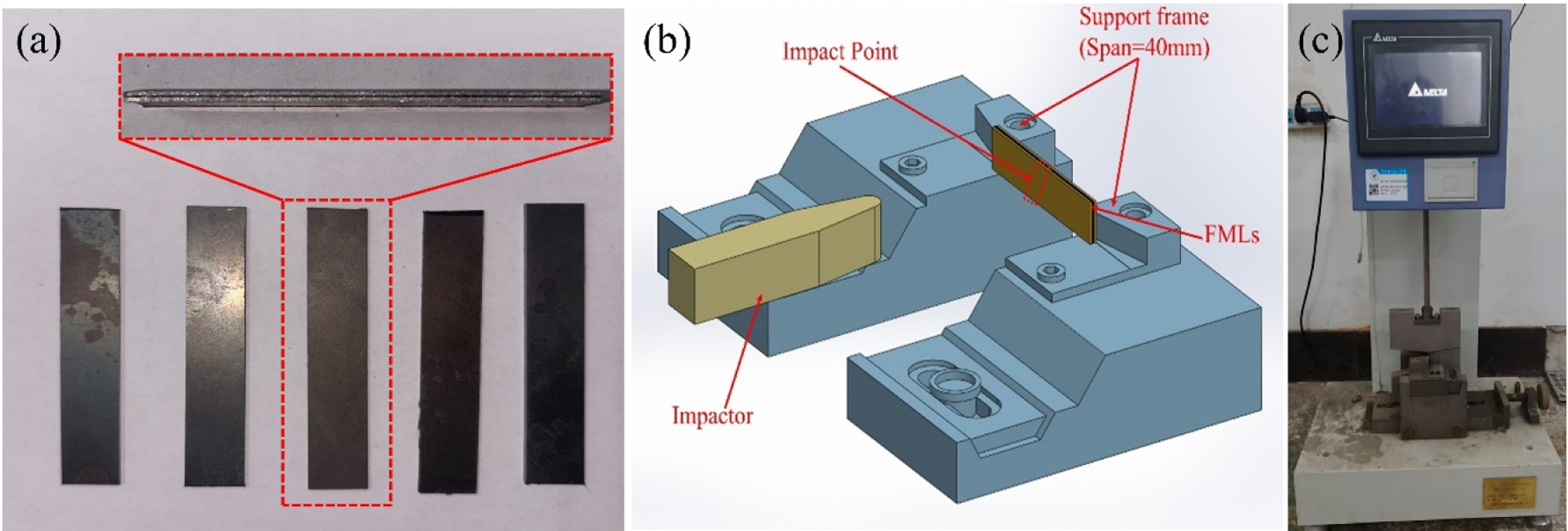
Numerical simulation of the FMLs
Nolinear finite element modelling
To characterize the deformation mechanisms and failure evolution, numerical simulations were implemented using the commercial finite element package ABAQUS/Explicit. This solver is highly effective for the nonlinear explicit dynamic analysis of high-rate impact events, accurately capturing the transient response of the GNP-reinforced CF/PEEK-Ti fiber metal laminates. The transient response was computed by simultaneously solving the equations of motion via an explicit dynamic procedure.
In order to achieve a balance between computational accuracy and efficiency, a mesh convergence study was conducted. Three distinct element sizes were subjected to evaluation: coarse mesh (1 mm), medium mesh (0.5 mm), and fine mesh (0.3 mm). As illustrated in Figure 3, a comparison of energy absorption curves under varying mesh densities is presented. It is evident that the peak load of the coarse mesh is 12% lower than that of the medium-density mesh. As the mesh size decreases, the computational results demonstrate a substantial convergence trend. The discrepancy in total absorbed energy between the medium-density mesh (0.5 mm) and the fine-density mesh (0.3 mm) is negligible. Furthermore, the variation in peak impact force is less than 5%. Consequently, all subsequent simulations employ a 0.5 mm mesh size to ensure reliable predictive results within a reasonable computational timeframe. Finite element mesh convergence verification.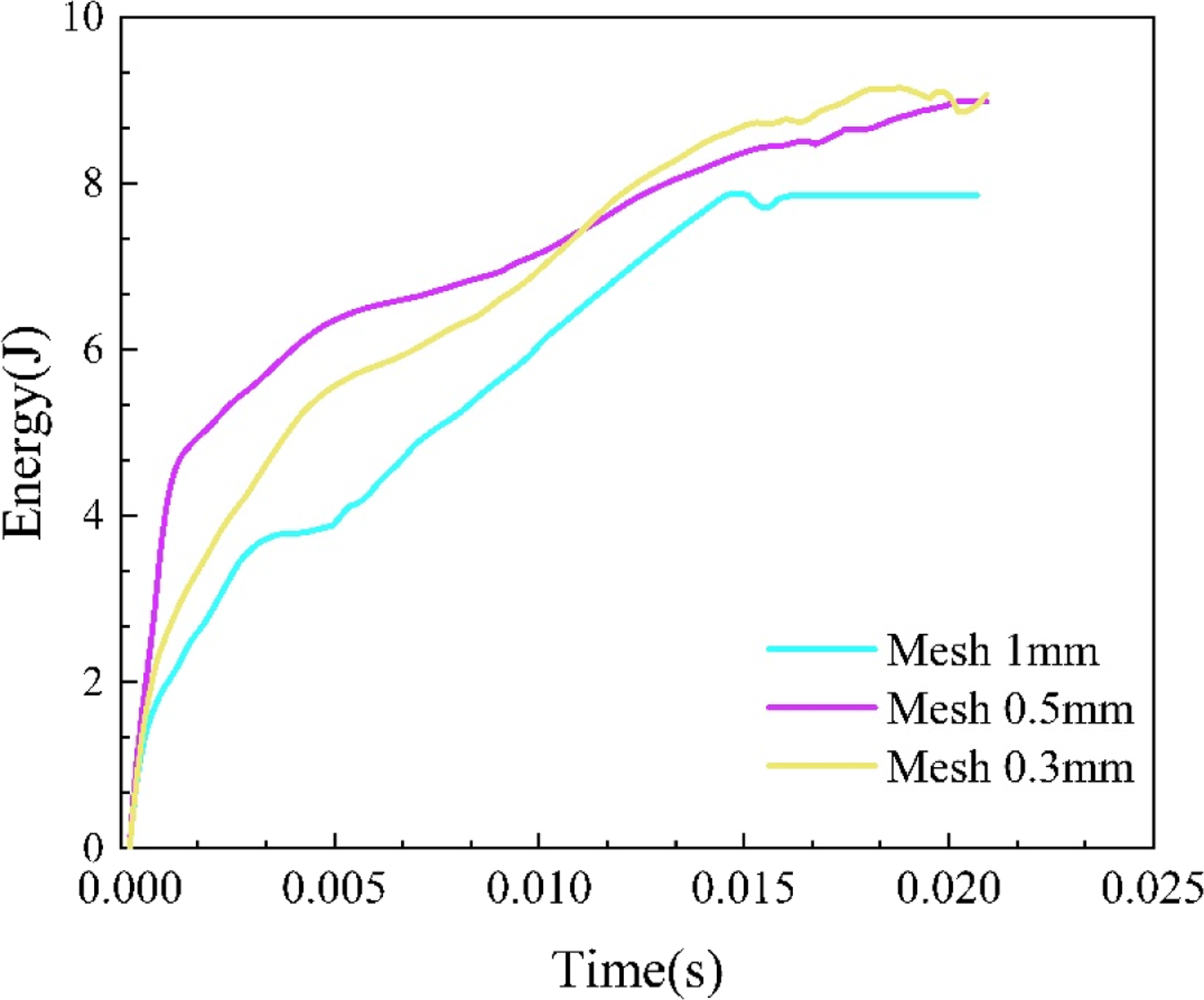
The CF/PEEK Ti finite element model consists of three parts, (1) TC4 titanium alloy metal, (2) CF/PEEK/GNPs composite, and (3) titanium alloy with CF/PEEK/GNPs composite between the PEEK layer. The finite‐element model employed simplified integration, using eight‐node linear hexahedral elements (C3D8R) to mesh both the metal layer and the impactor, while the composite layer was represented by eight‐node quadrilateral continuous shell elements (SC8R). Since the impactor did not undergo damage or deformation during testing, it was modeled as a rigid body. A depiction of this finite‐element setup is provided in Figure 4. The finite element model of FMLs.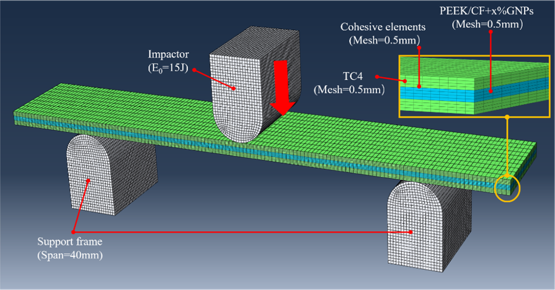
The impactor and supports were discretized as rigid bodies with 3 mm radii. A global contact algorithm incorporating penalty stiffness (friction coefficient = 0.3) governed their interactions with the laminate during impact simulation. To achieve experimental energy equivalence (15 J), an initial velocity of 87.306 m/s was prescribed to the impactor in FEA, ensuring consistency with physical tests prior to dynamic response computation. With reference to the experiments, the mesh size is determined by combining reasonable CPU time and accurate output results.
Material models
FMLs produce two types of failure in Charpy impact tests: (1) metal/composite layer deformation/damage, and (2) interlayer failure/damage. Therefore, the selection of appropriate material and damage models has a critical impact on the FEM analyses.
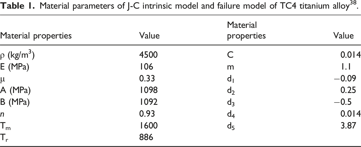
Intrinsic and damage model of metallic materials


Material parameters of J-C intrinsic model and failure model of TC4 titanium alloy 38 .
Intrinsic and damage model of PEEK/CF composites
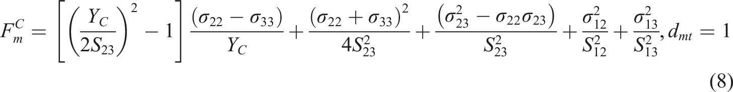
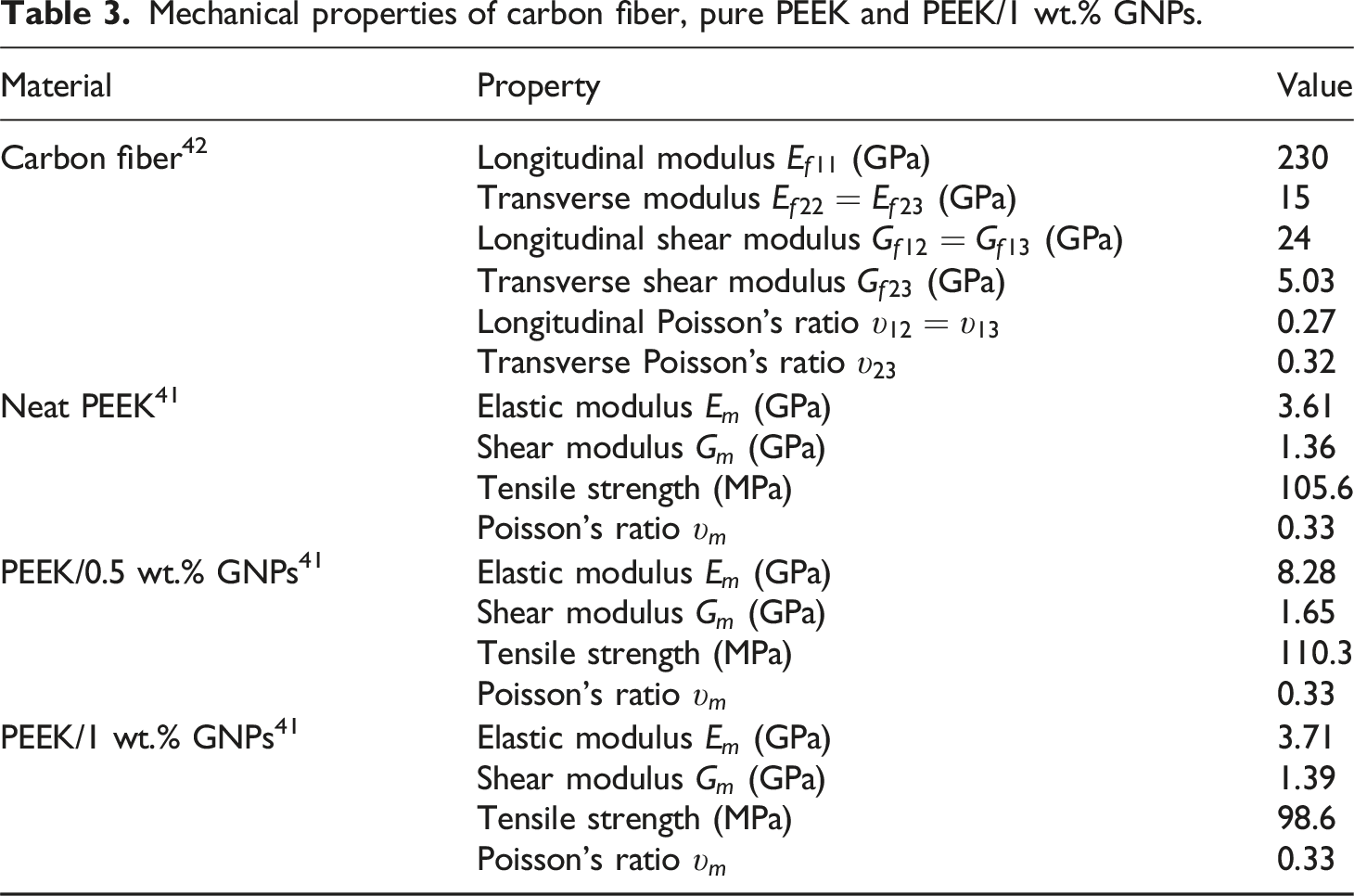
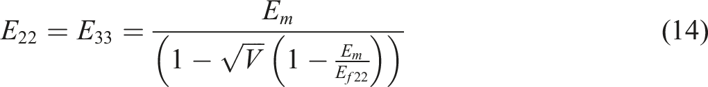
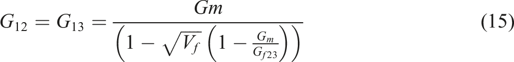
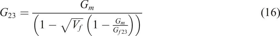
The finite element model of the PEEK/CF composite, which is an anisotropic material, was analyzed using the 2D Hashin damage model. The intrinsic model of this type of damage can be expressed in terms of the following equation 39 :
The fiber tensile damage 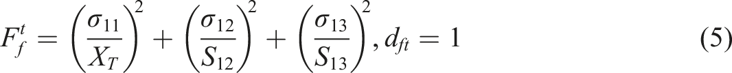
The fiber compressive damage 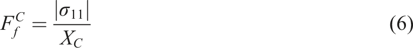
The matrix tension damage 
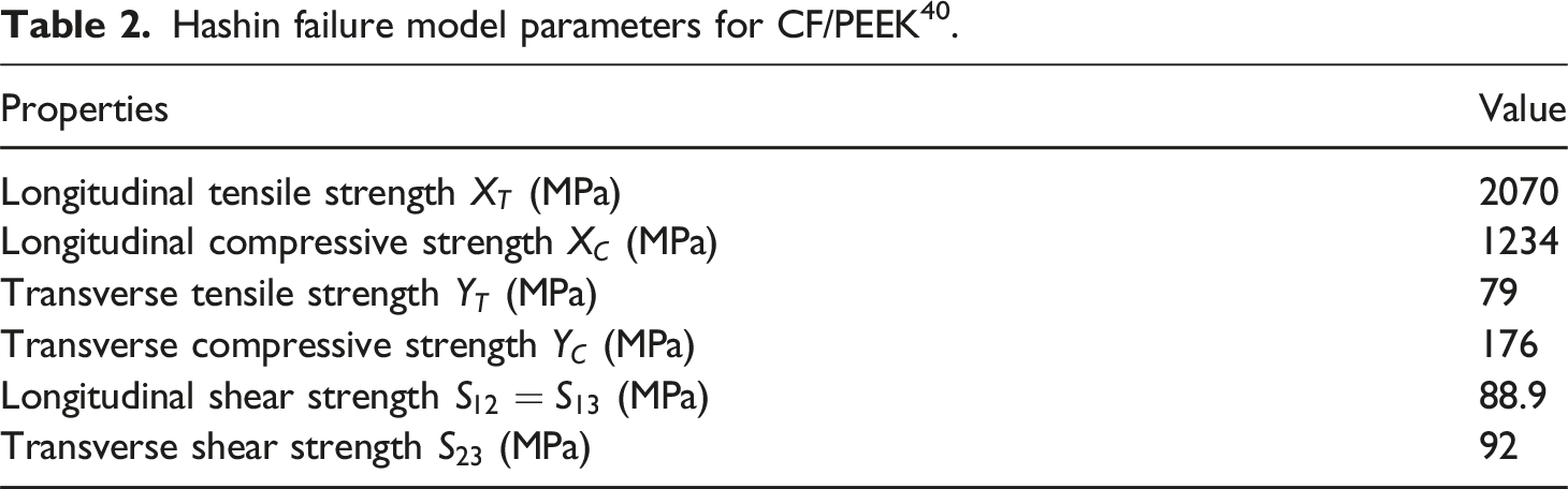
Hashin failure model parameters for CF/PEEK 40 .
Damage variables for fiber‐compressive failure, fiber‐tensile failure, matrix‐compressive failure, and matrix‐tensile failure are denoted by 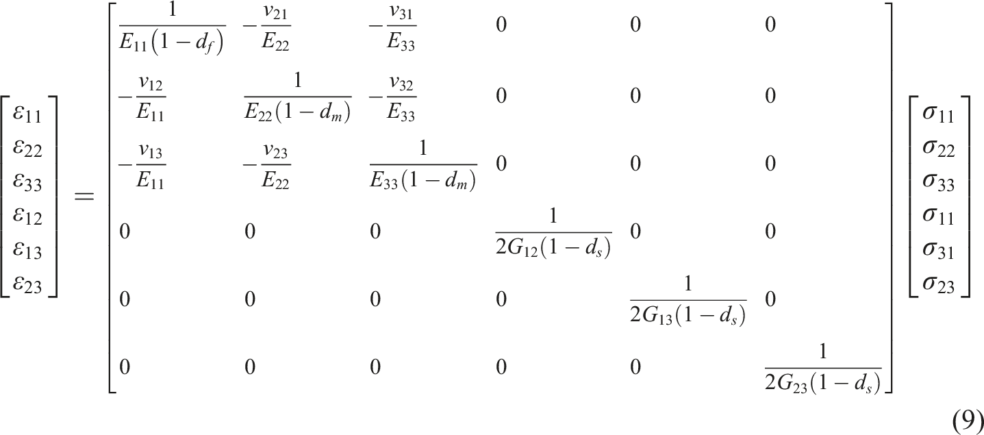


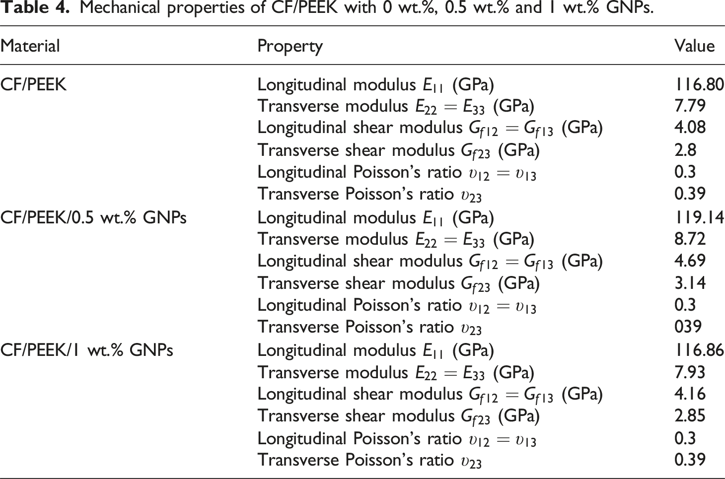
Mechanical properties of carbon fiber, pure PEEK and PEEK/1 wt.% GNPs.


Mechanical properties of CF/PEEK with 0 wt.%, 0.5 wt.% and 1 wt.% GNPs.
Damage model of interlayer interfaces
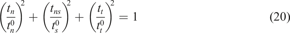
It is frequently the case that the interface between metal and fiber suffers delamination damage as a consequence of impact, therefore it was necessary to employ cohesive contact to simulate the interlaminar interface of FMLs. In order to simulate interlayer adhesion, surface-based constraints were applied between the TC4 titanium alloy and the CF/PEEK composite layers. The intrinsic model for tensile separation is presented in equation (19).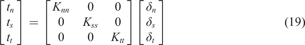
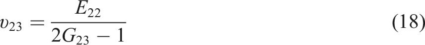
In this equation, the variables
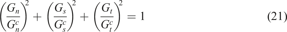
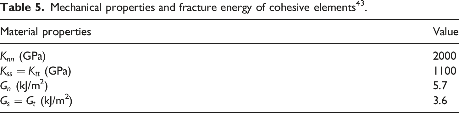
Mechanical properties and fracture energy of cohesive elements 43 .
Results and discussion
Impact properties of CF/PEEK-Ti hybrid laminates
The low‐velocity impact performance of CF/PEEK–Ti hybrid laminates depends on several factors, such as the fiber properties (stiffness, strength, and weave pattern), the polymer matrix characteristics (stiffness, strength, and toughness), and the laminate stacking sequence and orientation. Moreover, the way damage develops in fiber–metal laminates under impact is influenced by the shape of the impactor and its kinetic energy. In this study, we quantitatively explore how varying the graphene content affects the impact resistance of titanium‐reinforced CF/PEEK laminates at low velocities. To accomplish this, Charpy impact tests were carried out on the hybrid specimens.
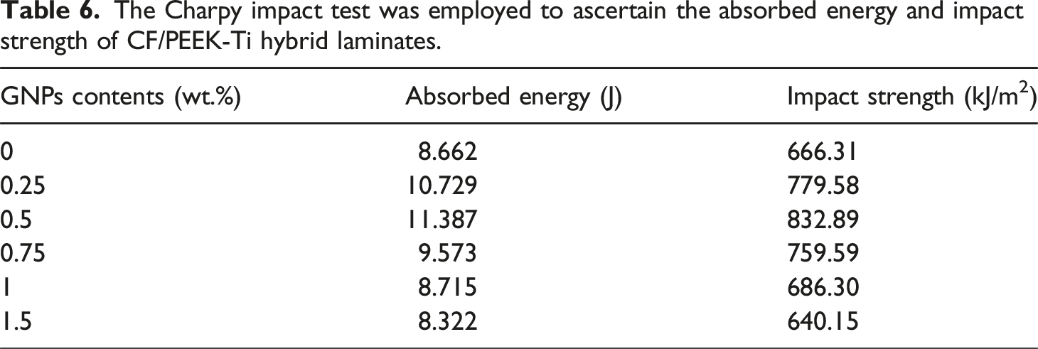
The averaged experimental results for Charpy tests on FMLs with varying graphene content are presented in Figure 5. The specific data are listed in table 6. Figure 5(a) illustrates the absorbed energy magnitude of FMLs with different graphene concentrations. The figure illustrates that the absorbed energy increases with the addition of graphene, up to a concentration of 0.5 wt.%. The data demonstrate that the incorporation of graphene into PEEK enhances the toughness and strength of FMLs, while also improving the ability to absorb impact energy. With a GNPs concentration of 0.5 wt.%, the FMLs achieved an absorbed energy of 11.38 J, showing a 23.8% enhancement compared to the control sample with 0 wt.% GNPs. The formation of a graphene nano-network structure within the PEEK matrix enables enhanced resistance to external impacts and loads. It can therefore be concluded that the addition of graphene to PEEK results in enhanced impact resistance. Upon increasing the graphene addition content to a value exceeding 0.5 wt.%, a gradual decline in the absorbed energy of FMLs is observed. When the graphene addition content exceeds 1 wt.%, the absorbed energy is observed to be smaller than that of FMLs without graphene. This phenomenon may be attributed to the excessive initial graphene addition, which results in agglomeration and stacking within the PEEK matrix, leading to stress concentration and premature delamination upon impact loading. This reduces the capacity to absorb impact energy, increasing the likelihood of failure and reducing the impact resistance. FMLs results of impact tests on different components, (a) absorbed energy and (b) impact strength. The Charpy impact test was employed to ascertain the absorbed energy and impact strength of CF/PEEK-Ti hybrid laminates.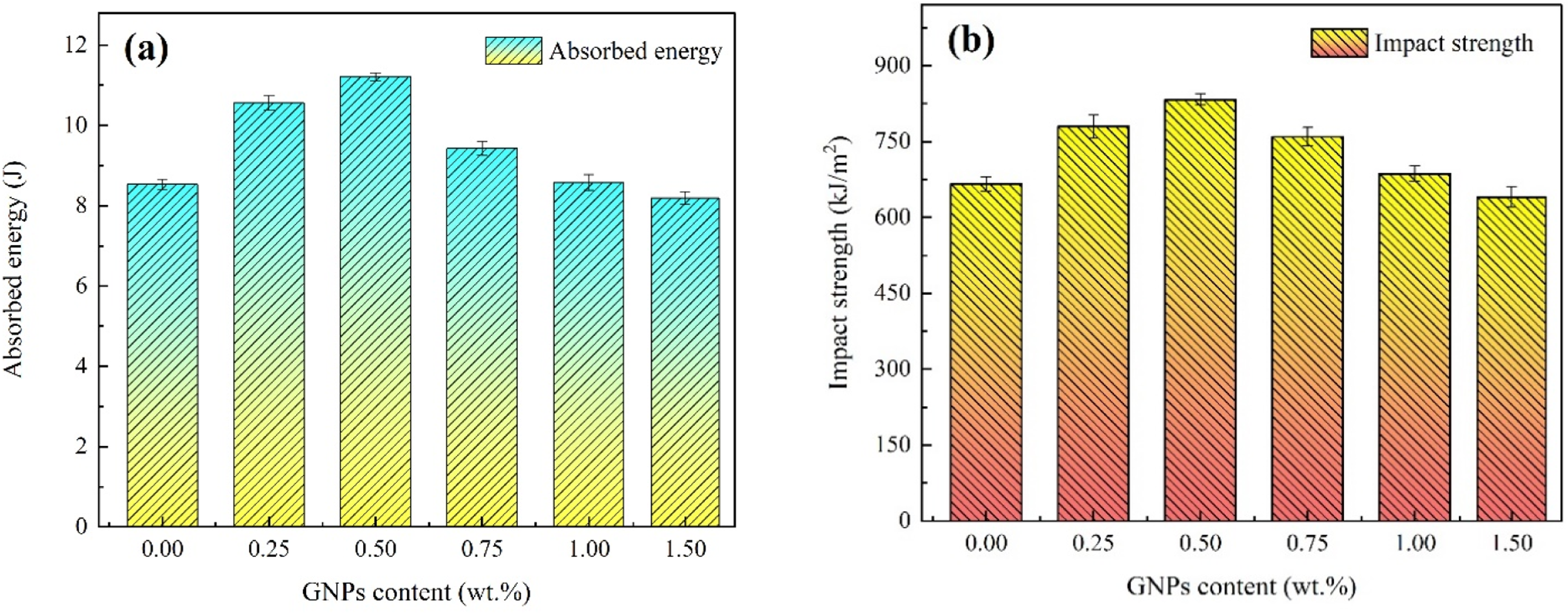
As illustrated in Figure 5(b), the trajectory of the impact strength of FMLs with varying graphene incorporation is consistent with that of the absorbed energy. At a graphene content of 0.5 wt.%, the impact strength of the FMLs reaches 832.89 kJ/m2, representing a 25% improvement over the 0 wt.% GNPs, which exhibited an impact strength of 666.31 kJ/m2. When the graphene addition level surpasses 0.5 wt.%, the impact strength of the FMLs begins to decrease as the graphene concentration continues to rise. Ultimately, the impact strength of the corresponding FMLs at 1.5 wt.% exhibits a negative growth and is less than that of the impact strength at 0 wt.% content. This demonstrates that the addition of an excess of graphene nanoparticles does not result in an overall enhancement of the laminate’s strength.
Figure 6(a)–(f) illustrate the disparate impact damage incurred by specimens with varying concentrations of GNPs introduced post-Charpy impact experimentation. Figure 6(a) presents the optical micrographs depicting the impact damage observed in pure FMLs. It can be observed that the pure FMLs subjected to impact exhibited a relatively minor bending angle, and the FMLs displayed a notable delamination phenomenon (illustrated by the blue rectangular box) as well as a significant fracture of the central fiber layer (depicted by the yellow circle). As shown in Figure 6(b), incorporating 0.25 wt.% GNPs leads to a modest increase in the bending angle compared to the pure FMLs after impact. However, a substantial delamination phenomenon (blue rectangular box) and fiber layer fracture (yellow circle) persist. In contrast, Figure 6(c) depicts the impact damage of FMLs with 0.5 wt.% GNPs, which exhibits a smaller bending angle and minimal internal damage to the fiber layer. Only a small portion of the matrix exhibits bending, and a minor delamination phenomenon is observed. This suggests that the incorporation of a specific quantity of GNPs can enhance the performance of PEEK and strengthen the interfacial bonding between the fiber and the metal. Optical images of impact damage of FMLs with different compositions, (a) untreated FMLs, (b) 0.25 wt.%, (c) 0.5 wt.%, (d) 0.75 wt.%, (e) 1.0 wt.%, (f) 1.5 wt.% GNPs-FMLs.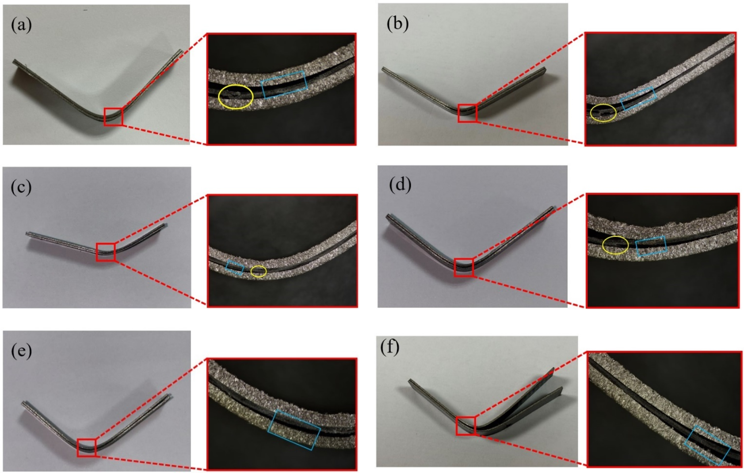
However, the addition of GNPs at a concentration of 0.75 wt.% in Figure 6(d) results in a significant delamination phenomenon in the FMLs and a notable degree of fiber layer fracture. Secondly, the increasing content of GNPs is observed to result in a notable increase in the delamination phenomenon of the FMLs impact specimens, as illustrated in Figure 6(e) and (f) for FMLs with 1 wt.% GNPs and 1.5 wt.% GNPs, respectively. Additionally, the bending angle of FMLs after impact is observed to decrease with the increasing content of GNPs. This phenomenon can be attributed to the formation of a significant number of GNPs agglomerates, which collectively result in a reduction in the interfacial contact ability between the fibers and the metal.
Microstructure analysis
Figure 7 illustrates the micro-surface topography of fractured fiber within FMLs, exhibiting differing concentrations of GNPs. Figure 7(a1)–(a3) depicts the fractured fiber surfaces of pure FMLs. It is evident that the fiber surfaces are relatively smooth, indicating that the PEEK/carbon fiber interfacial contact ability is weak and the transfer of load is not pronounced. Figure 7(b1)–(b3) displays the fractured fiber surfaces of FMLs with an addition of 0.5 wt.% GNPs. The images reveal that the fiber surfaces are coated with a GNPs and PEEK mixture. The rougher fiber textures improve the contact between the PEEK and carbon fiber, thereby enhancing the interfacial strength of the FMLs. Figure 7(c1)–(c3) depicts the fractured fiber of 1 wt.% GNPs-enhanced FMLs. Figure 7(c1) illustrates that a portion of the matrix has accumulated in a pile-like structure (yellow circled part). Figure 7(c2) depicts the presence of both agglomerated matrix (yellow circled part) and coalesced GNPs (blue circled part). The magnified image of Figure 7(c3) demonstrates that a considerable number of agglomerates have formed on a single fiber as a result of the GNPs. This phenomenon compromises load transmission efficiency across the fiber-PEEK interface, diminishing interfacial bonding strength. Consequently, the load-transfer capability of fiber-metal laminates (FMLs) is significantly impaired. It can thus be surmised that the incorporation of a greater quantity of GNPs will result in a heightened degree of agglomeration, which will subsequently impair the interfacial properties of FMLs. SEM images of fracture surfaces with different contents of GNPs reinforced with FMLs, (a1) (a2) (a3) pure FMLs, (b1) (b2) (b3) 0.5 wt.% GNPs-FMLs, (c1) (c2) (c3) 1.0 wt.% GNPs-FMLs.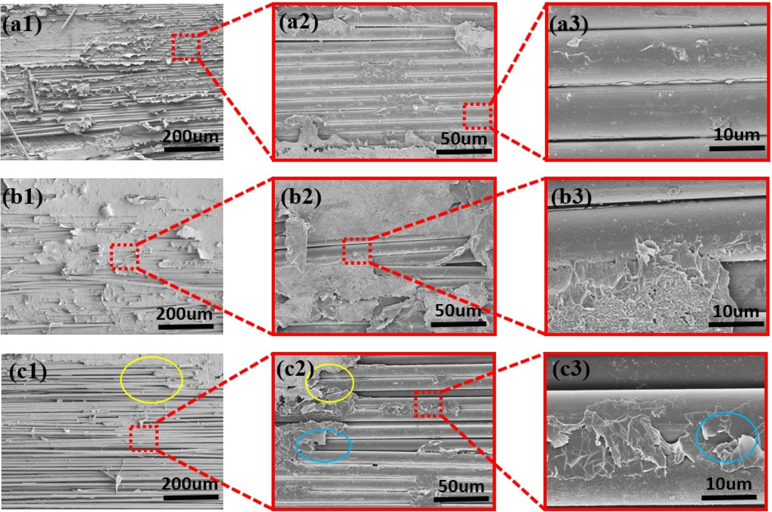
As illustrated in Figure 8, the fracture surface micrograph and energy-dispersive X-ray spectroscopy (EDS) spectrum of 1 wt.% GNPs-FMLs after impact reveal the presence of these nanomaterials. Figure 8(a) illustrates the microscopic surface of carbon fibers encapsulated within the matrix, with their locations indicated by green arrows. It was observed that within the matrix surrounding the carbon fiber, graphene nanoparticles (illustrated by blue circles in the image) were present on the matrix surface, exhibiting luminescence. This phenomenon can be attributed to the conductive properties of the graphene nanoparticles when exposed to the electron beam emitted by the scanning electron microscope. As illustrated in Figure 8(b) and (c), the energy dispersive spectra for carbon (C) and oxygen (O) elements are presented, respectively. The distinct concentration of carbon elements is clearly visible in the blue-circled regions of Figure 8(a), thereby providing further confirmation of the presence of graphene nanoparticles. SEM and EDS of the impact fracture surface of 1 wt.% GNPs-FMLs: (a) SEM of fracture surface, (b) EDS of C element of impact fracture surface, (c) EDS of O element of impact fracture surface.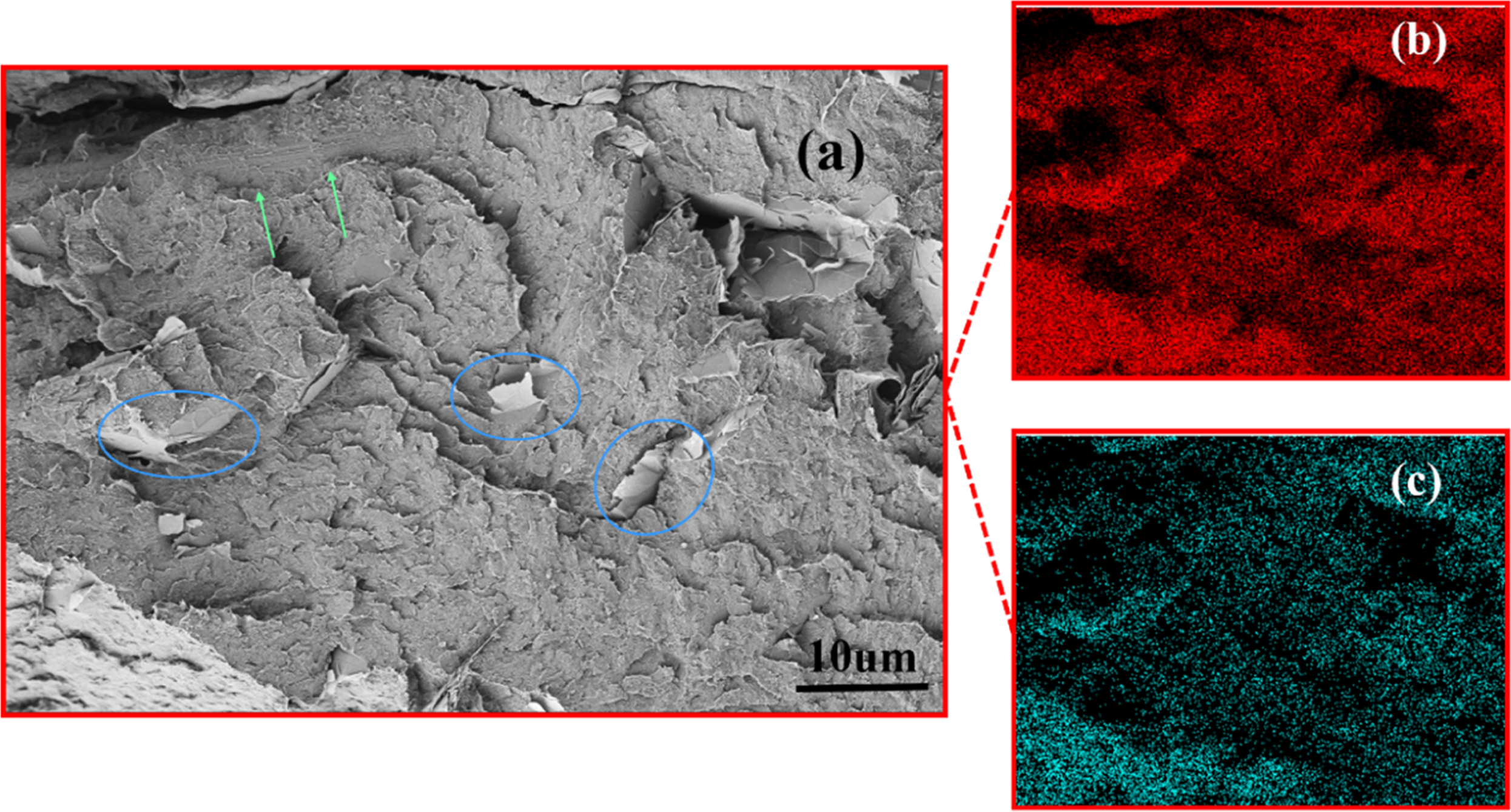
Validation of the finite element model
Validating numerical models against experimental data represents a fundamental objective in computational mechanics. To assess the accuracy of the nolinear finite element framework, this work benchmarks simulated energy absorption in graphene-modified FMLs against physical test data under identical impact energy conditions. Velocity profiles (initial/residual) derived from the FEM solution further demonstrate model-experiment correlation. Figure 9 subsequently visualizes von Mises stress distributions across impact-tested laminates with varied graphene concentrations (neat, 0.5 wt.%, 1 wt.%). It is evident that following 15 J of impact, the FMLs with a 0.5 wt.% GNPs content generate the highest stress levels, while the pure FMLs produce the lowest stress levels. The location of the maximum stress for both is in the outer fiber layer of the impact bend. However, the maximum stress for the FMLs with a 1.5 wt.% GNPs content is in the outer fiber layer of the two sides of the impact bend. The maximum stresses of FMLs with 0 wt.%, 0.5 wt.% and 1 wt.% GNPs are 1931 MPa, 2334 MPa and 2039 MPa, respectively. In comparison to the maximum stresses of pure FMLs, the maximum stresses of FMLs with 0.5 wt.% GNPs are increased by 21%. The equivalent stresses in the finite element model of FMLs following the application of 15 J of impact energy.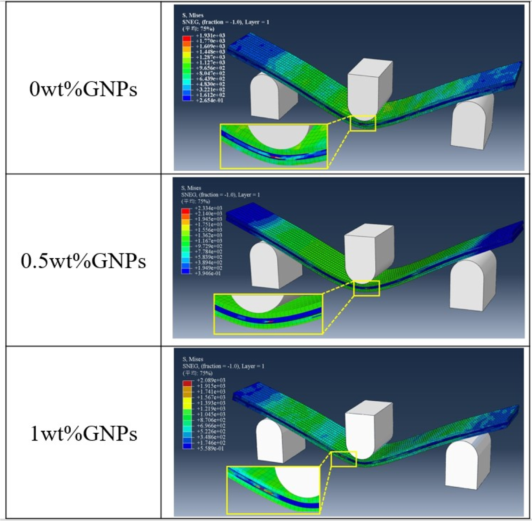
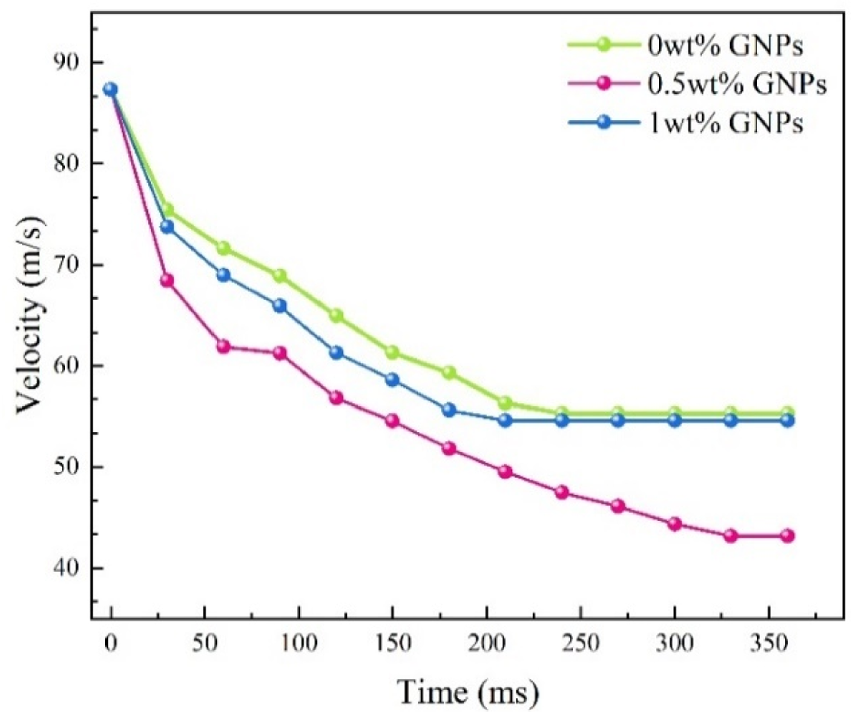
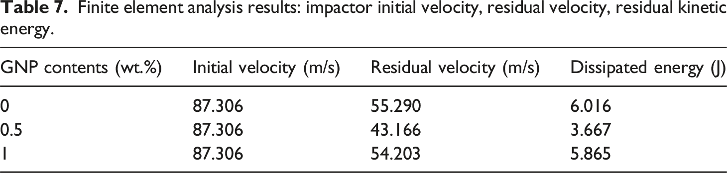
Figure 10 depicts the velocity variation curves of the impactors under FEA for FMLs with varying GNPs fractions. Velocity profiles of impactors striking three laminate types—pristine FMLs, 0.5 wt.% GNP-reinforced FMLs, and 1 wt.% GNP-enhanced FMLs—were determined through finite element modeling. To maintain experimental load consistency, the FEA impactor’s initial velocity was fixed at 87.306 m/s. Post-impact residual velocities measured 55.290 m/s (pristine FMLs) and 54.203 m/s (1 wt.% GNPs), while the 0.5 wt.% GNP composite exhibited a significantly lower 43.166 m/s. This 21.9% reduction relative to pristine FMLs indicates superior energy absorption capacity, correlating with enhanced impact resistance. Using equation (22), residual kinetic energies were calculated as 6.016 J (0 wt.%), 3.667 J (0.5 wt.%), and 5.865 J (1 wt.%). These results are presented in Table 7, which lists the residual velocities and residual kinetic energies of the impactors obtained from the finite-element analyses. Finite element analysis results: impactor velocity decay curve. Finite element analysis results: impactor initial velocity, residual velocity, residual kinetic energy.

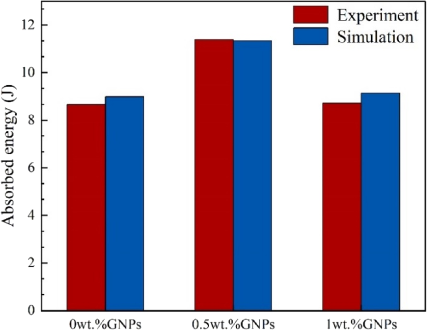
The finite element simulation demonstrates that the energy lost by the impactor is entirely transferred to the FMLs. The energy lost by the impactor for the three groups of 0 wt.%, 0.5 wt.%, and 1 wt.% is calculated to be 8.984 J, 11.333 J, and 9.135 J, respectively, through the application of equation (23). Furthermore, the absorbed energy of the FMLs in the finite element simulation is identical to that lost by the impactor, as previously described. It was not possible to obtain continuous experimental load-displacement curves due to the use of a non-instrumented impact testing machine. Consequently, the validation of the finite element analysis (FEA) model concentrated on total absorbed energy, the most critical indicator of fuel management system (FMS) impact resistance. As illustrated in Figure 11, the numerically predicted energy-time history curves for specimens containing 0 wt.%, 0.5 wt.%, and 1 wt.% GNPs are presented. The simulated energy for all three specimens eventually plateaued at 8.984 J, 11.333 J, and 9.135 J, respectively. A detailed analysis of the curve trends depicted in Figure 11 reveals that the FMLs with 0.5 wt.% GNPs content exhibited a more stable and gradual plateau, indicating superior impact resistance. Figure 12 consequently benchmarks simulated versus experimental impact energy absorption in FMLs. The comparative analysis encompasses laminates with 0 wt.% (pristine), 0.5 wt.%, and 1 wt.% GNPs. Simulation results reveal a non-monotonic energy absorption trend: initial enhancement followed by reduction with increasing graphene concentration. This pattern aligns with experimental observations, where 0.5 wt.% GNPs yielded 11.333 J absorption energy - a 26.1% improvement over pristine FMLs. However, further GNP addition diminished energy absorption capacity, evidenced by the 1 wt.% GNP composite’s modest 1.6% gain (9.135 J). As demonstrated in Figure 12, experimental measurements recorded absorption energies of 8.662 J (0 wt.%), 11.387 J (0.5 wt.%), and 8.715 J (1 wt.%), while corresponding simulations produced 8.984 J, 11.333 J, and 9.135 J. A correlation of greater than 98% between the model and the experiment confirmed the accuracy of the computational framework. Subsequently, the individual elements of the finite element model, namely the TC4 metal plate, carbon fiber/PEEK and the cohesive element, are subjected to further analysis to identify any potential issues such as damage or deformation. The finite element energy absorption history data is presented herewith. FMLs finite element verification: Absorbed energy limit meta-analysis results versus experimental measurements.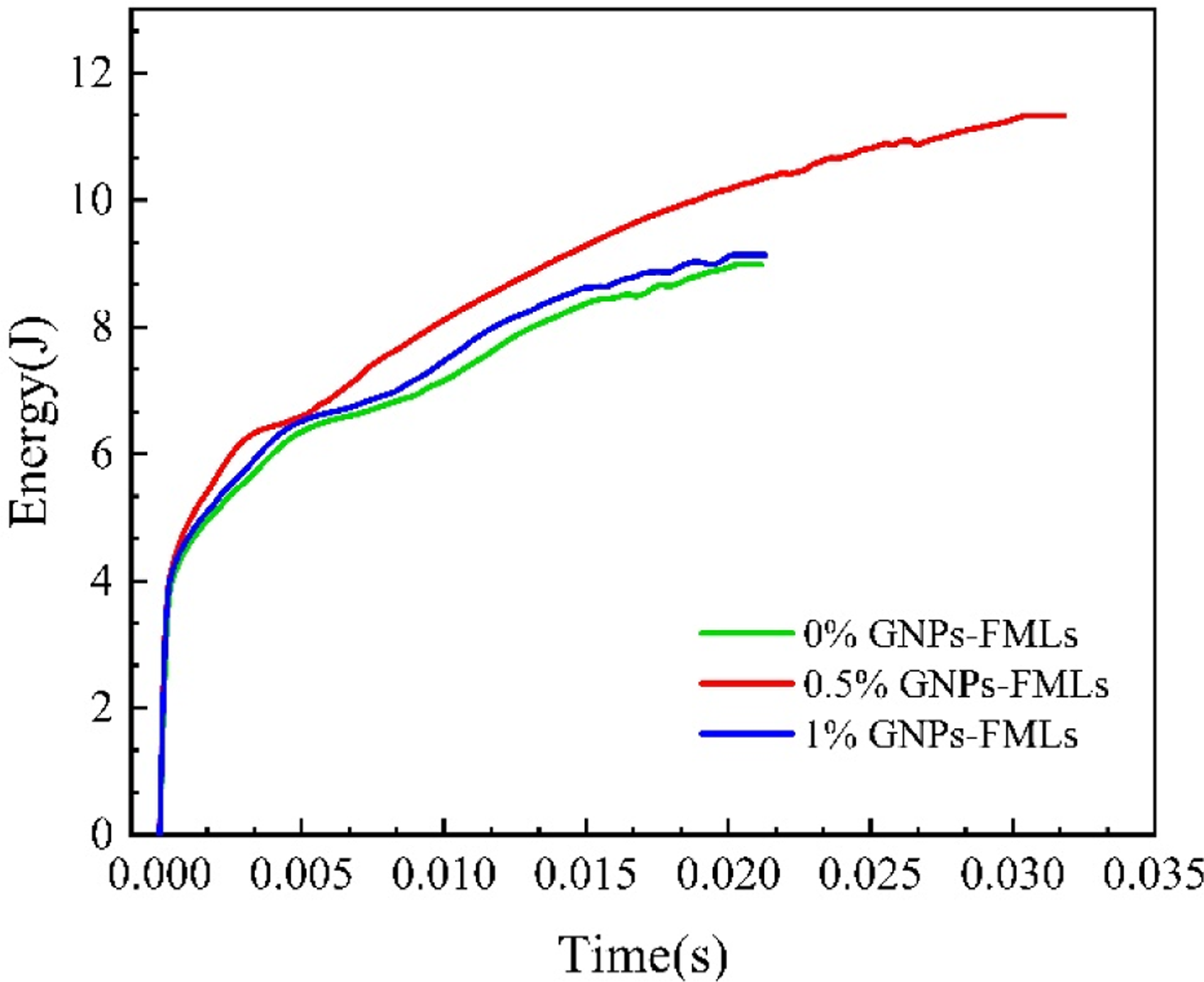
Numerical results
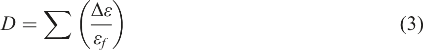
The paper discusses the consistency between the finite element model and the experimental data, and then uses the finite element model to further investigate the failure modes and damage mechanisms of the FML when subjected to an impact. Since the FMLs are not a single structure, but a mixed fiber and metal molding, the layers are also of different compositions when the finite element model is built. Consequently, FMLs damage analysis requires dual examination: (1) Material deformation/failure in TC4 alloy and carbon fiber/PEEK layers. (2) Interfacial decohesion between metallic and composite phases. The finite element implementation adopted Hashin’s criterion for composite ply damage, with distinct tensile/compressive failure modes characterized for both carbon fiber and PEEK matrices. In this case, the damage threshold of the Hashin criterion is between 0 and 1, where D = 0 represents no damage to the fiber matrix layer and D = 1 indicates that some damage and complete failure of the fiber matrix layer occurs. As shown in Figure 13, the contour plots of carbon fiber and PEEK matrix with Hashin damage criterion are shown for 0 wt.%, 0.5 wt.% and 1 wt.% GNPs after 15 J energy impact, respectively. As shown in Figure 13(a1), (b1), (c1), it is easy to see that the carbon fiber layers of the three groups of GNPs all failed, and the carbon fiber layers of the 0 wt.% and 1 wt.% GNPs failed at the location of the impact site. The 0.5% w/w GNPs, which absorbed more impact energy, had a more diffuse area of damage. Figure 13(a2), (b2), (c2) shows the PEEK matrix layers of the three groups of GNPs, again the failure regions of the PEEK matrix layers of the 0 wt.% and 1 wt.% GNPs at impact occur in the same areas as the fiber layers of the two groups, whereas the PEEK matrix layers of the 0.5 wt.% GNPs do not show any significant damage at the impact regions, but are better distributed to both sides of the FMLs where the damage occurred. This provides strong evidence that incorporating a specific amount of GNPs enhances the impact strength of carbon fiber/PEEK composites. This improvement is due to the GNPs increasing fracture toughness as well as reinforcing the cohesive and interfacial strength between the layers within the PEEK matrix. Hashin’s damage criteria for (a) 0 wt.% GNPs, (b) 0.5 wt.% GNPs, (c) 1 wt.% GNPs.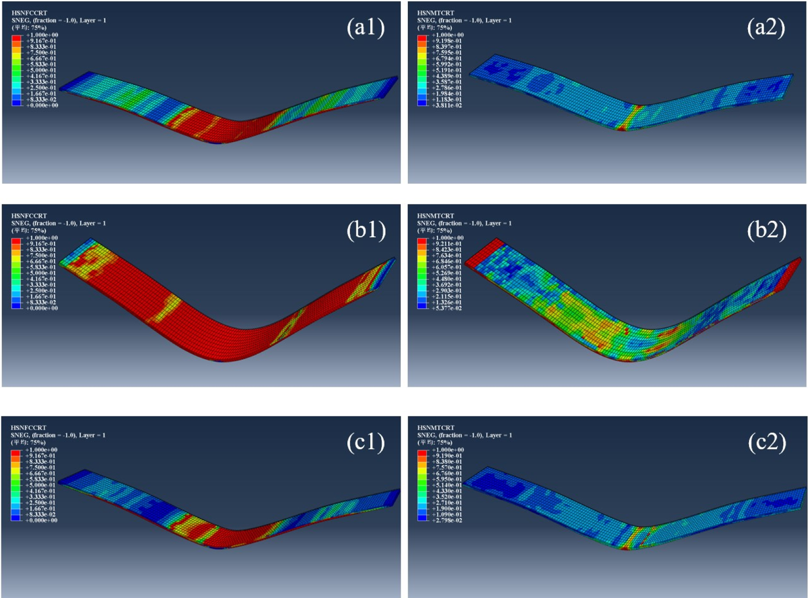
The validity of the Cohesive Zone Model (CZM) was verified by comparing the predicted failure modes with the experimental observations. Figure 14(a) presents the comparison between the numerical damage contours (CSDMG) and the optical images of the tested specimens. Damage of cohesive zone (a) 0 wt.% GNPs, (b) 0.5 wt.% GNPs, (c) 1 wt.% GNPs.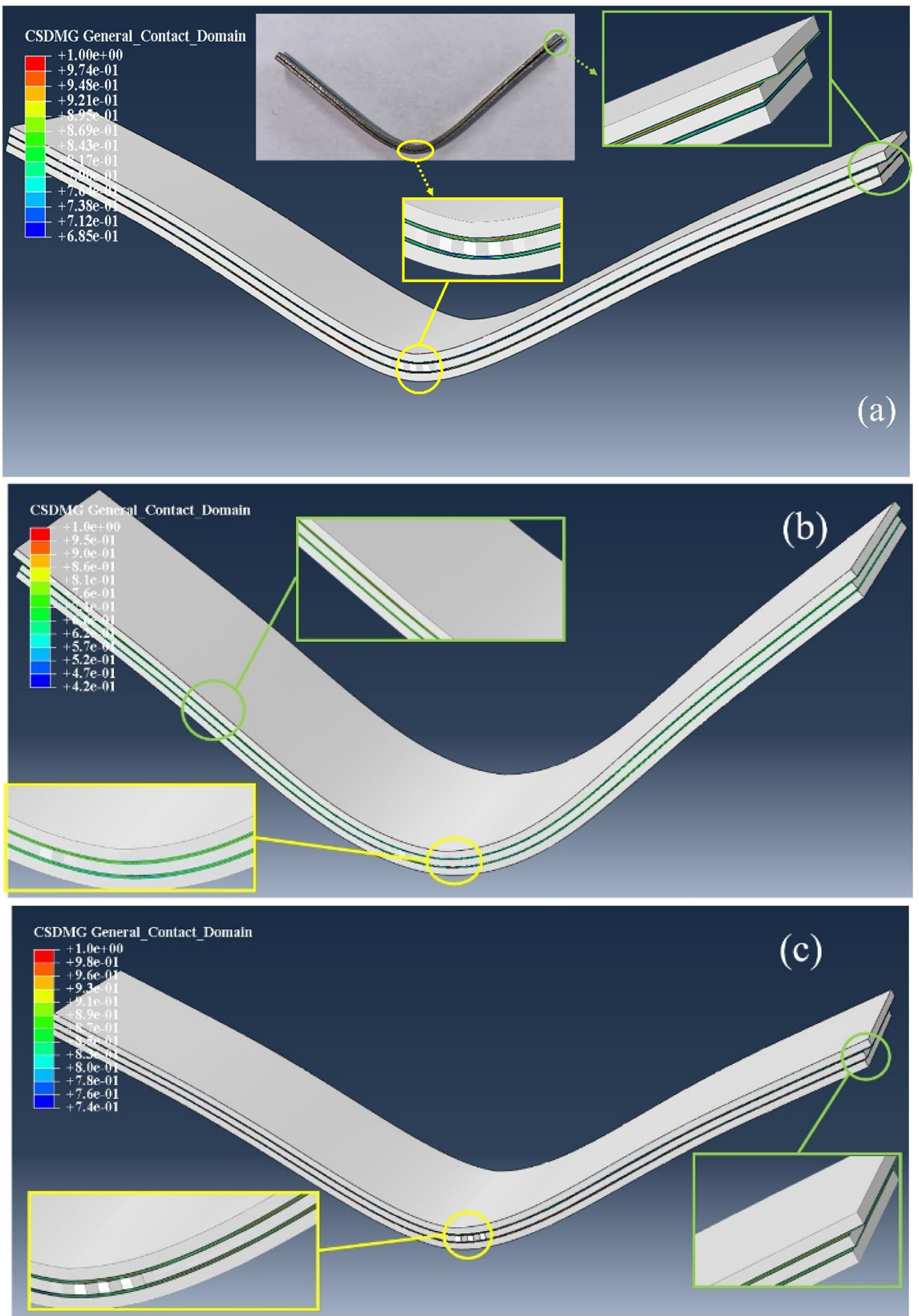
It is evident that the finite element model accurately predicted the location and extent of delamination, which primarily occurred at the titanium-composite interface. The high degree of agreement between experimental results and finite element analysis with regard to absorbed energy, coupled with the strong overlap in the regions where delamination occurred, confirms that the bonding parameters employed in the model adequately reflect the interfacial fracture behavior of GNP-reinforced fiber-reinforced metal composites. Figure 14 illustrates the evolution of damage in the cohesive elements across different regions of the FMLs. Panels (a)–(c) display the damage distribution of these cohesive elements after subjecting laminates with 0 wt.%, 0.5 wt.%, and 1 wt.% GNP to impacts of the same energy, respectively. Similarly, the damage threshold for the cohesive unit model is also between 0.0 and 1.0, and the cohesive unit in this region is damaged and fails when the damage parameter D = 1. Experimental observations revealed that, following impact, the FML specimens exhibited pronounced delamination and deformation, accompanied by failure of the adhesive joint between the metal and fiber layers. Similarly, finite element simulations demonstrated analogous delamination in the FML model, with the cohesive elements at the metal–fiber interface undergoing damage. Figure 14(a) and (c) shows the FMLs with 0 wt.% and 1 wt.% GNPs, where the delamination and buckling of the carbon fiber layer occurred in the central region of the impact, and at the distal end, it can be clearly seen that the metal layer in the upper half of the model and the fiber layer in the middle of the model were torn, and the cohesive unit between the two layers was completely failed. 0.5 wt.% GNPs of FMLs were impacted with the same energy and their cohesive unit was damaged after the impact. Figure 14(b) presents the damage evolution in the cohesive elements of the FML containing 0.5 wt.% GNPs when subjected to an identical impact energy. Compared to the specimens with 0 wt.% and 1 wt.% GNPs, only a limited region around the impact site exhibits damage and delamination in the 0.5 wt.% GNP case. Additionally, separation between the metal and fiber layers is observed near the specimen’s far end. These findings suggest that introducing an optimal amount of GNPs into the FML facilitates more effective distribution of the impact load than in laminates composed solely of carbon fiber and polymer. In other words, GNPs not only reinforce the PEEK matrix but also improve interfacial adhesion and overall cohesion between the metal and fiber layers.
The above analysis shows that the finite element analysis model developed in this paper can fully represent the experimental results such as the occurrence and development of damage after impact on FMLs. In practice, variations in manufacturing lead to experimental outcomes that deviate modestly from FEM predictions, with the simulations occasionally overestimating the results. Specific reasons for this include voids in the matrix and fibers during the preparation process, inadvertent fiber misalignment and the effects of stress concentrations when cutting the specimen, which are not specifically accounted for in the finite element simulation. Meanwhile, during the experimental impact process, the unstable impact kinetic energy causes the transverse shear stress generated by the compressive stress to fluctuate accordingly.
Conclusions
This research characterizes the impact behavior of a novel TC4/PEEK/carbon fiber thermoplastic laminate incorporating 0.25–1.5 wt.% graphene nanoplatelets (GNPs). A computational framework was established to replicate damage morphologies in fiber-metal laminates (FMLs) post-impact. The methodology comprised: (1) Anodization treatment of TC4 substrates. (2) Charpy impact testing of GNP-enhanced FMLs. Deformation and failure mechanisms were further quantified via finite element simulations at 0, 0.5, and 1 wt.% GNP loadings. Key findings demonstrate that 0.5 wt.% GNP reinforcement yields optimal impact resistance, exhibiting 23.8% higher energy absorption and 25% increased impact strength versus non-reinforced counterparts. Finite element models for Charpy impact tests on FMLs with 0, 0.5, and 1 wt.% GNPs were developed to predict damage in carbon fiber/PEEK/GNP composites. The established finite element model precisely simulated the damage behavior of these super-hybrid structures, showing that FMLs with 0.5 wt.% GNPs performed better than both untreated and 1 wt.% GNP FMLs in terms of fiber, matrix, and interfacial damage. This finite element model can be further adapted to include various GNP concentrations in FMLs, enhancing its utility in optimizing the impact resilience of advanced composites.
Footnotes
Declaration of conflicting interests
The authors declared no potential conflicts of interest with respect to the research, authorship, and/or publication of this article.
Funding
The authors disclosed receipt of the following financial support for the research, authorship, and/or publication of this article: This work was financially supported by Shenyang Municipal Science and Technology Plan Project (Grant No. 24-213-3-31), Natural Science Foundation of Liaoning Province (2025-MS-128).
Data Availability Statement
The data that support the findings of this study are available from the corresponding author upon reasonable request.