
Abstract
Metal mesh-reinforced thermoplastic composites have emerged as promising candidates for lightweight, energy-absorbing structures in aerospace applications. However, their mechanical performance is highly sensitive to fabrication parameters such as winding angle, layer sequence, and forming pressure. In this study, a hybrid tube structure composed of GF/PP prepreg and stainless-steel mesh was fabricated using a manual winding process, aiming to optimize the structural design and processing conditions. A custom-built winding platform was used to ensure stable operation, and the effects of lay-up configuration and compaction pressure were investigated. The [45°/-45°/metal mesh/-45°/45°] lay-up with 40 N pressure offered superior surface finish and mechanical balance through improved interfacial bonding. Mechanical tests, including tensile, compressive, and shear experiments were conducted according to ASTM standards. The GF/PP composite exhibited high tensile strength along the fiber direction and stable shear resistance, while the metal mesh demonstrated elastic–plastic behavior under uniaxial loading. The results confirm the feasibility of the proposed process and lay-up strategy, providing a basis for structural design and simulation of high-performance hybrid components.
Keywords
Introduction
Metal/composite hybrid structures have gained increasing attention in the design of energy-absorbing components 1 for automotive 2 and aerospace 3 applications, where demands for high strength-to-weight ratios, 4 progressive failure behavior, and structural recoverability 5 are critical. Among them, fiber-reinforced thermoplastics offer excellent formability, damage tolerance, 6 and recyclability, 7 while metallic meshes can provide additional structural reinforcement and energy dissipation through plastic deformation. 8 Integrating these materials into a unified hybrid system holds promise for achieving tunable mechanical performance under complex loading scenarios, including axial compression, bending, and shear. Recent studies have further investigated the influence of temperature and environmental factors on the fracture toughness and failure mechanisms of advanced composite systems. 9 In addition, the design of composite honeycomb and lattice structures has been shown to enhance load distribution and improve energy absorption efficiency through optimized surface matching 10 and tailored in-plane stiffness configurations. 11 These findings provide valuable guidance for the design and optimization of hybrid metal-composite structures under complex mechanical and thermal loading conditions. However, the final mechanical behavior of such hybrid structures is strongly influenced by processing routes, 12 including lay-up sequence, forming pressure, and the interface between components. Recent studies have shown that metal-polymer hybrid tubular and circular structures exhibit superior crashworthiness and energy absorption capabilities under quasi-static loading, with deformation modes strongly governed by hybrid configuration and material distribution. 13 Comparative investigations further indicate that the mechanical response of hybrid circular structures is highly sensitive to loading direction, particularly under quasi-static lateral loading, highlighting the role of material hybridization and internal architecture. 14 In addition, the introduction of triggering mechanisms has been demonstrated as an effective approach to tailor collapse behavior and improve energy absorption efficiency in hybrid pipes subjected to axial compression. 15 From a broader perspective, recent reviews emphasize the rapid development of innovative and cost-effective hybrid composite materials for crashworthiness applications, while underscoring the importance of reliable fabrication routes and material-level optimization. 16 In particular, manual winding or press-forming approaches introduce variations in layer alignment, fiber distribution, and interfacial bonding factors that directly affect crashworthiness 17 or energy absorption capacity. Tsartsaris et al. 18 studied the low-velocity impact behavior and damage mechanisms of fiber metal laminates, combining experimental testing with finite element simulations to elucidate energy absorption and interfacial failure modes. Zhang et al. 19 investigated the axial crushing response and energy absorption optimization of thin-walled aluminum/CFRP hybrid tubes using explicit finite element modeling and multi-objective optimization techniques. Ozturk et al. 20 reviewed recent advancements in thermoplastic composite materials and manufacturing technologies in the aerospace industry, highlighting their advantages in formability, recyclability, and impact resistance. Guo et al. 21 studied the low-velocity impact response and post-impact vibration characteristics of GF/PP thermoplastic composite sandwich structures, focusing on damage evolution and energy absorption behavior.
Nevertheless, current studies on thermoplastic composite-metal wound tubes remain relatively scarce, particularly with respect to integrated design–manufacturing strategies and their influence on constituent material behavior. The absence of a clear process-structure-property framework limits their potential for reliable engineering applications. To address these challenges, this study establishes a systematic fabrication and material evaluation for [±45°/metal mesh/±45°] hybrid tubular configurations based on GF/PP prepregs and stainless-steel meshes, explicitly linking winding design, forming parameters, and constituent-level mechanical performance.
In this study, structural prototypes of hybrid tubes are fabricated under controlled winding parameters, 22 with visual and dimensional inspections guiding the selection of optimal forming conditions. A preliminary process evaluation using manually controlled parameters was conducted to establish a basis for future automated laboratory-scale winding systems. Then, based on the established process, mechanical testing is performed on GF/PP specimens 23 and metallic mesh samples to evaluate tensile, compressive, and shear properties under realistic conditions. 24 The resulting dataset not only clarifies the impact of fabrication parameters on constituent material performance, but also supports the design and modeling of future energy-absorbing hybrid structures in lightweight vehicle and aerospace applications25.
Materials and winding method
Material
Properties of unidirectional GF/PP prepreg.
Winding fabrication method
The fabrication process of the tube involves inner layer winding, metal mesh placement, outer layer winding, and other related steps, as shown in Figure 1(a). In this study, manual winding is employed, and the systematic refinement of process parameters lays the foundation for future implementation of automated control systems to enable laboratory-scale automated winding. In this work, each GF/PP layer (ply) is defined as a single full-coverage winding pass with a uniform fiber orientation. Accordingly, the lay-up [45°/-45°/metal mesh/-45°/45°] represents two individual GF/PP plies on both the inner and outer sides of the metal mesh, each ply having a thickness approximately equal to that of one prepreg tape. Winding fabrication method. (a) Basic winding method (b) (c) Winding path and process parameters (d) Schematic diagram of braided structure winding (e) Schematic diagram of same-direction winding within a layer.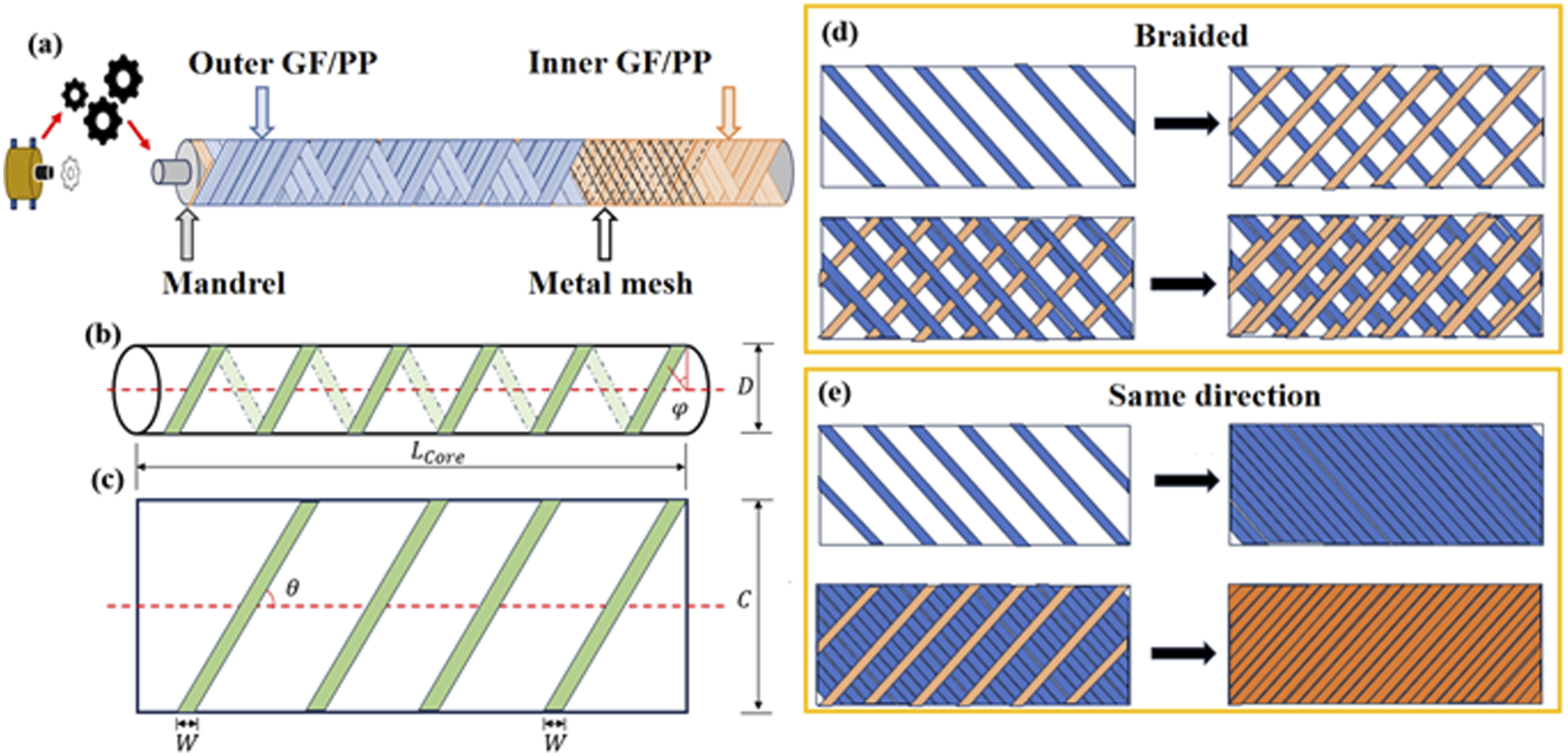
The three-layer configuration [45°/metal mesh/-45°] follows the same winding logic as the five-layer structure, in which the inner and outer composite layers are formed by independent single-angle winding passes and therefore also exhibit a single-prepreg thickness, as illustrated in Figure 1(e).
By contrast, the lay-up [±45°/metal mesh/±45°] corresponds to a reciprocating interlaced winding strategy, where the prepreg tape is continuously deposited with alternating fiber orientations without cutting. As a result, the inner and outer composite layers are formed as single layers with an effective thickness of approximately twice the prepreg tape thickness, as shown in Figure 1(d).
The braided structure is spirally wound, with bidirectional cross-overlapping. The prepreg is conceived as a single tape of sufficient length, and the mechanical tape feeder moves back and forth on the mandrel, keeping 45° in the forward direction to complete the winding path. The prepreg tape is turned to −45° in the length direction and wound in the reverse direction. This operation is repeated until the prepreg tapes of the entire tube are closely arranged and connected, as shown in Figure 1(d). The winding method is shown in Figure 2. First, complete the winding of one prepreg tape, then wind the second prepreg tape in the opposite direction, and then repeat the process until the braided structure winding process is completed, as shown in Figure 1(e). Fabrication process (a) Inner layer winding (b) Metal mesh and outer layer (c) Outer layer winding (d) Finished tube preparation.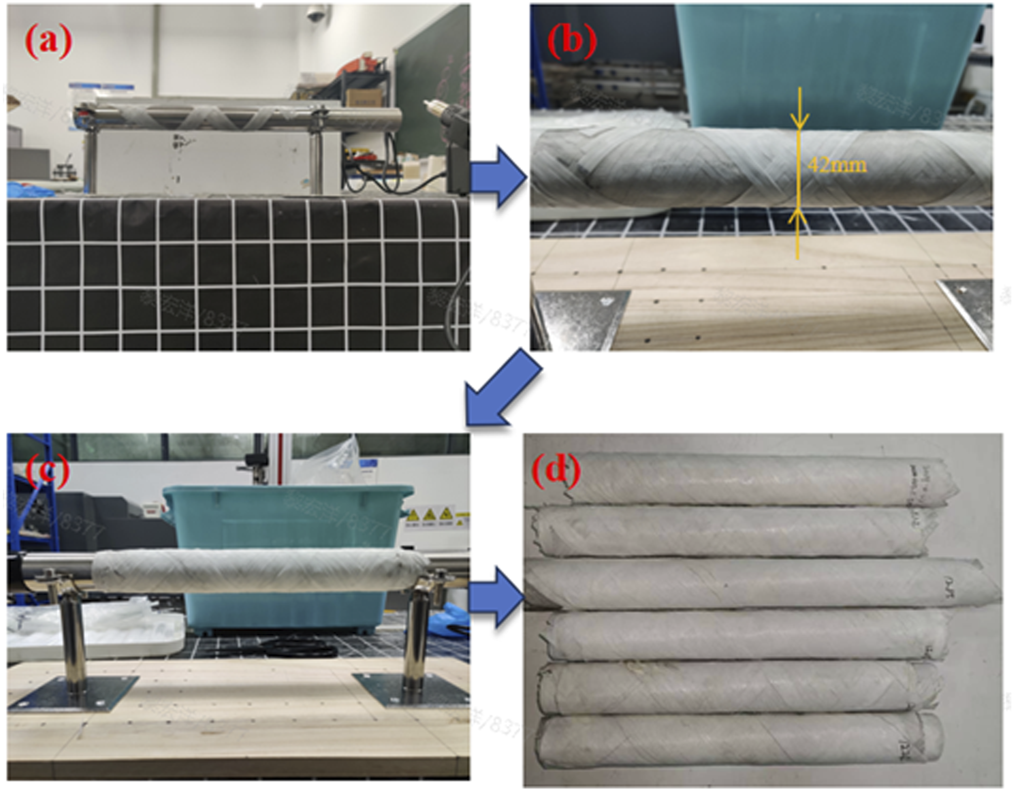
Tube structure design
The tube is fabricated on a mandrel, and thus its inner diameter is determined by the outer diameter of the mandrel. In this study, a mandrel with an outer diameter of D = 38 mm and a length of L Core = 500 mm is used. Due to the adoption of manual winding, each winding path is completed using a single cut prepreg tape, applied from one end of the mandrel to the other. The width of each prepreg tape is 5 mm. To ensure complete coverage of the mandrel surface, key parameters of the winding process must be recorded. 26
While various winding angles can be selected, this study focuses on the fundamental winding method of metal mesh/GF/PP hybrid tubes and the resulting structural performance, serving as a preliminary investigation prior to automation. Since the manual winding process is entirely controlled by hand, some winding angle deviation is inevitable. To minimize the influence of human error, a winding angle of θ = 45°, which is easier to control, is adopted.
Length of single prepreg tape L
Composite
:
Mandrel circumference C:
Curve growth arc length La:
Single-turn growth angle 
Number of winding turns N:
In the geometric design of the tubes, the outer diameter and length of the mandrel directly determine the inner diameter and overall shape of the final component. In this study, a mandrel with an outer diameter of 38 mm and a length of 500 mm is employed, forming the foundational framework for the tube’s geometry. During the winding process, 5 mm wide prepreg tapes are used to fully cover the mandrel surface, with each tape having a length of 500 mm. The calculated circumference of the mandrel is approximately 120 mm.
To simplify the winding operation and enhance consistency, a winding angle of 45° is selected. This angle not only facilitates operation but also helps reduce the angular deviations caused by manual handling, thereby improving overall winding precision. Based on geometric calculations, the growth angle per winding turn is approximately 21°18′, resulting in about nine winding turns for full coverage.
It is important to note that the accuracy of the winding path is critical to the final geometry of the tube, particularly in multi-layered structures. Even minor geometric deviations can significantly impact the mechanical performance of the component. Therefore, both the winding angle and applied pressure are strictly controlled, and each layer is carefully adjusted to ensure that the resulting geometry and mechanical properties conform to the intended design specifications. The actual winding process is shown in Figure 3. Winding layer tubes (a) braided [±45°/metal mesh/±45°] (b) [45°/metal mesh/-45°] (c) [45°/-45°/metal mesh/-45°/45°] Surface of tubes formed by different force (d) 30 N (e) 40 N (f) 50 N.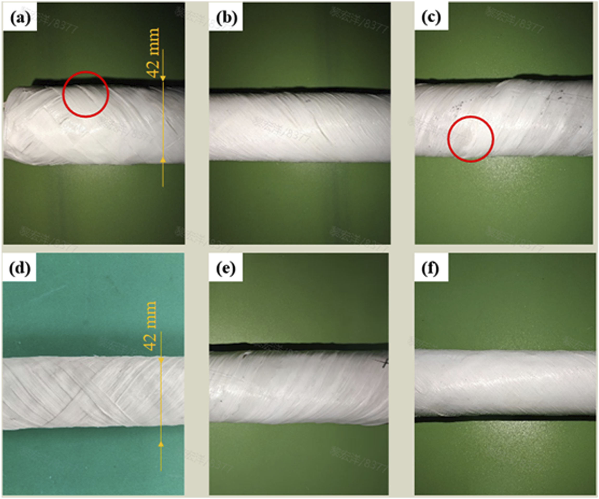
The fabrication process begins with the inner layer of GF/PP composite material being wound onto a rotating mandrel to form the base structure of the tube. A [45°/-45°] winding pattern is employed to ensure uniform material distribution in both axial and circumferential directions, thereby enhancing the load-bearing performance. During winding, the tension of the fiber tape is carefully controlled to prevent local relaxation or stress concentration. The overlapping method is adjusted to ensure tight interlayer bonding and to minimize the inclusion of air pockets during the process. To further improve structural stability, a hot air gun set at 270°C is used to soften the material during winding, promoting enhanced adhesion between layers. Upon completion of the inner layer, a metal mesh is applied to reinforce the tube’s load-bearing capacity. The mesh must be laid evenly and in close contact with the underlying layer to avoid localized gaps that could cause stress concentrations. Throughout the mesh-laying process, the tensile deformation of the mesh is carefully controlled to maintain minimal gaps, allowing it to effectively reinforce the structure under axial and circumferential loads. A compaction pressure of 40 N is applied using a roller, sufficient to ensure bonding without damaging the composite prepreg. The GF/PP material is then wound over the mesh layer to form the outer structural layer, using a [-45°/45°] lay-up to further optimize interlayer adhesion. During this process, uniform pressure and tension are maintained across all layers. After winding, the tube is allowed to cool naturally before undergoing final quality inspections, including dimensional measurements and surface deburring, to ensure the fabricated tube meets the requirements for cutting and mechanical testing.
Under the initial conditions, no additional compaction pressure was applied-only fiber tension was used during fabrication-and the tube were prepared using a braided structure. The resulting sample is shown in Figure 3(a). It was observed that the braided [±45°/metal mesh/±45°] configuration exhibited significant thickness non-uniformity, particularly in the overlapping regions of the braid. This inconsistency was attributed to the combined effects of manual winding inaccuracies and the finite width of the prepreg tape, leading to overall structural thickness variation. For the single-layer unidirectional [45°/metal mesh/-45°] laminate structure, compaction pressure was applied during fabrication. It was found that these single-layer tubes were generally more flexible compared to their double-layer counterparts, and the bonding between the prepreg and metal mesh was not consistently effective. In addition, variations in tape alignment led to weaker regions near the edges, as illustrated in Figure 3(b). In contrast, the [45°/-45°/metal mesh/-45°/45°] double-layer structure allowed for more precise control during manual winding, resulting in improved surface quality and reduced gaps between adjacent prepreg tapes, as shown in Figure 3(c). The double-layer layup also compensated for the shortcomings of the single-layer sandwich structure, which is prone to forming interfacial gaps between the prepreg and metal mesh layers.
In this work, the term “pressure” refers to the normal force applied by the compaction roller (N), rather than a force per unit area, as force-based control ensures better repeatability under manual winding conditions. As shown in Figure 3, when a compaction force of 30 N is applied using the pressure roller, the prepreg tapes can be bonded together as a whole. However, following the placement of the metal mesh layer, partial separation between the inner and outer adjacent layers is observed, indicating insufficient consolidation. When the compaction force is increased to 40 N, the layers exhibit no visible voids and passed visual inspection criteria, and no visible gaps are observed on the surface. At a force of 50 N, some of the prepreg tapes-having been softened by heating-begin to flatten noticeably, resulting in increased tape width and decreased thickness. This leads to an appearance that does not meet the expected quality standards. Under the same heating conditions, applying forces greater than 50 N causes this issue to occur more frequently. Based on these observations, a compaction pressure of 40 N is selected as the optimal value for the fabrication process.
The [45°/-45°/metal mesh/-45°/45°] lay-up configuration was adopted, and a compaction pressure of 40 N was applied to minimize the overall thickness and approach the theoretical target. The sample exhibited superior surface smoothness compared to both the braided and single-layer tube structures. Additionally, the overall resistance to compression and bending was significantly improved. By comparing the fabrication outcomes of tubes with different lay-up sequences and molding pressures, the optimal configuration was identified as the double-layer structure with a [45°/-45°/metal mesh/-45°/45°] lay-up under a forming pressure of 40 N.
Experiment and Samples
Experiment Settings
The TG-DSC experimental method is to place about 5 mg of GF/PP composite material sample in a crucible, set the heating rate to 5°C/min, and the temperature range is from room temperature to 800°C. The composite material tensile test refers to the standard ASTM D3039-17, with a constant loading rate of 2 mm/min. The composite material compression test refers to the standard ASTM D6641, using a combined loading compression (CLC) fixture and a constant loading rate of 1 mm/min. The in-plane shear performance test of the composite laminate was carried out according to ASTM D3518. Among them, in the tensile and shear tests, digital image correlation (DIC) was used to measure the full-field strain on the front of the sample, and a strain gauge was used to measure the strain on the back. In the shear test, the sample was measured by DIC. The metal mesh was tested using an extensometer. The DIC and static strain gauge combined test environment is shown in Figure 4. DIC and static strain gauge combined test.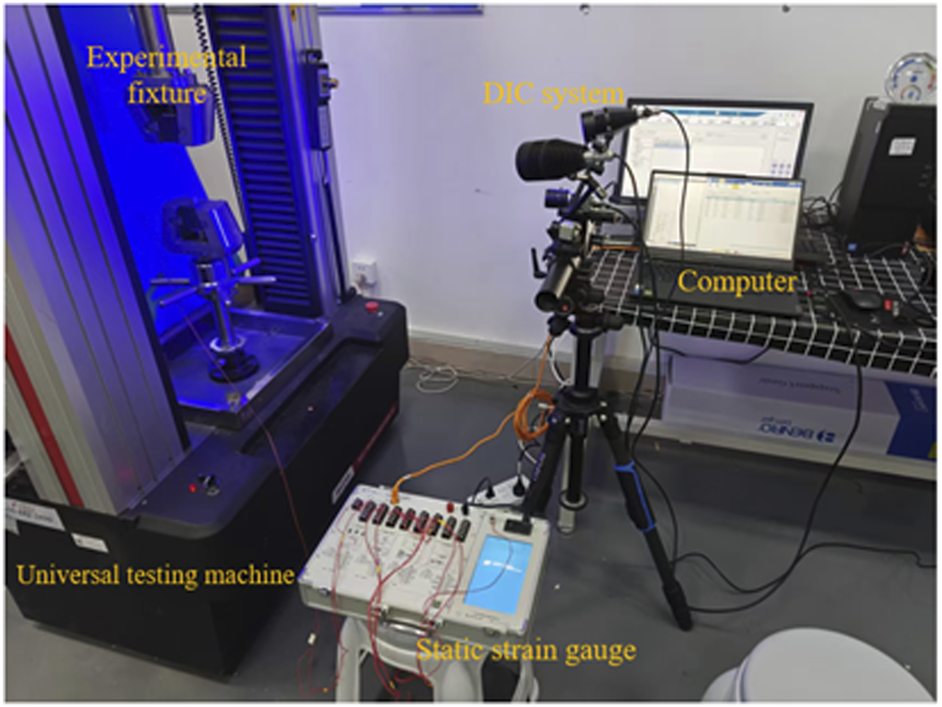
Samples preparation
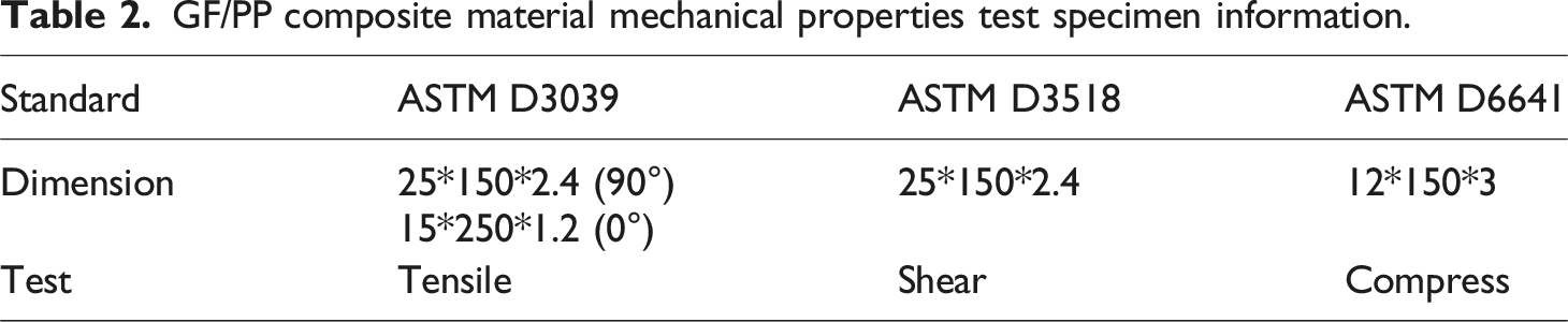
First, use the high temperature resistant hot press plate as a platform and use alcohol to clean the surface to remove dust. Then arrange the samples layer by layer according to the order of sample laying required by the experimental standard. Then use a hot air gun to heat at 270°C and a hand roller to apply a normal compaction force of 40 N (force-based control) during heating. Finally, use a 2 kg counterweight to evenly compact and let it stand. After cooling, use sandpaper to remove burrs on the surface of the sample. The reinforcement sheet used for the sample is made of aluminum alloy. The metal mesh tensile test refers to the standard ASTM E8. The metal mesh is scored along the grid direction and cut into rectangular mesh pieces with a length of 110 mm and a width of 20 mm using scissors. The gauge length is 50 mm. For each mechanical test, three specimens were prepared and tested under identical conditions to ensure repeatability. The tensile properties of the metal mesh are measured. The specimen is clamped on both sides with coarse sandpaper. The sample size is shown in Figure 5 and Table.2. GF/PP composite material mechanical properties test and specimen. (a) 0° tensile test (b) 0° compress test (c) 90° tensile test (d) Tensile shear test (e) 0° GF/PP tensile test specimens (f) 90° GF/PP tensile test specimens (g) Tensile shear test specimens (h) 90° GF/PP compress test specimen (i) 0° GF/PP compress test specimen (j) Metal mesh tensile specimens. GF/PP composite material mechanical properties test specimen information.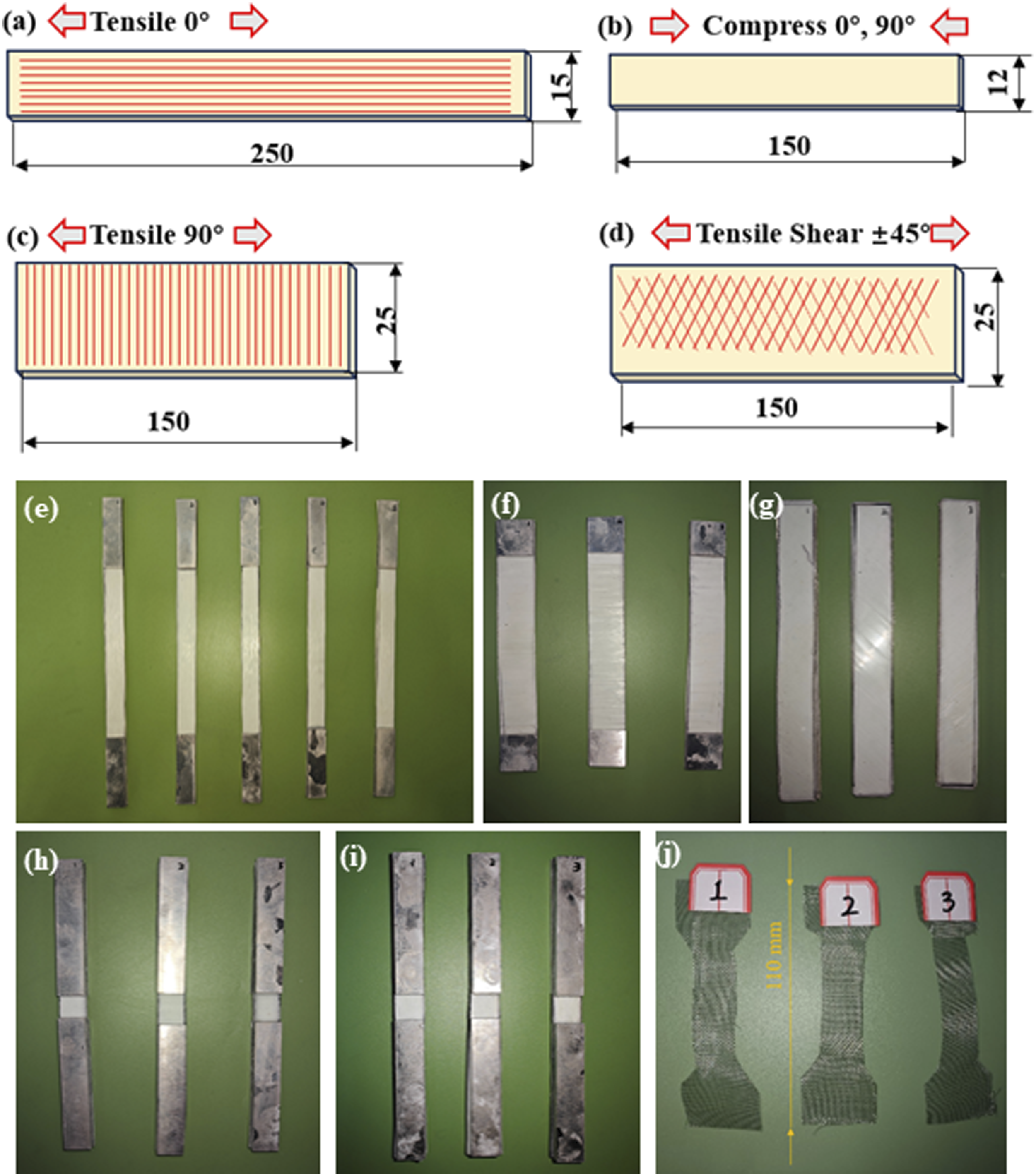
Result and discussion
Thermal analysis of GF/PP
The TG and DSC curves of GF/PP are presented in Figure 6. Thermogravimetric analysis (TGA) was conducted to evaluate the thermal stability of the GF/PP composite. As shown in Figure 6, the onset of significant thermal degradation occurs at approximately 350°C, marking the initial decomposition of the polypropylene matrix. This temperature indicates the upper limit for thermal processing without inducing matrix breakdown. A sharp mass loss is observed between 350°C and 480°C, corresponding to the active decomposition phase of the polymer component. After this stage, the residual mass stabilizes at approximately 58.4% of the original weight, primarily attributed to the thermally stable glass fibers that remain intact after matrix volatilization. The results demonstrate that the composite maintains good thermal stability up to 300°C, which satisfies the requirements for hot-air-assisted winding and subsequent forming processes. The processing temperature of 270°C did not induce thermal degradation, as it remained below the TGA-determined decomposition onset and was applied locally for a short duration. The clear decomposition interval and substantial residue content confirm the composite’s suitability for thermoplastic processing, and provide reference parameters for controlling heating conditions during fabrication. TG and DSC curve of GF/PP.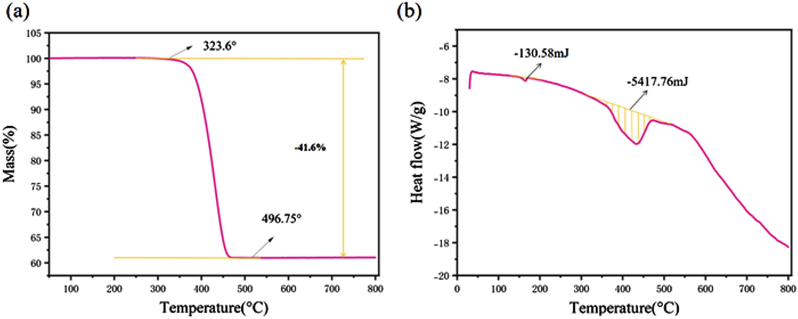
GF/PP performance
GF/PP tensile performance
As shown in the stress–strain curve in Figure 7(a), the measured longitudinal tensile strength (X
t
) of the GF/PP composite is 719.73 MPa, indicating a substantial load-bearing capacity in the axial direction. The corresponding elastic modulus (E
1
) is 30.07 GPa. For comparison, the manufacturer-reported properties of the prepreg material in the fiber direction are an elastic modulus of 28 GPa and a tensile strength of 750 MPa. After the forming process, the elastic modulus in the fiber direction shows a slight increase, while the tensile strength exhibits a reduction. This phenomenon may be attributed to improved fiber alignment during the filament winding process, which enhances the overall stiffness of the material. However, excessive local compression during resin melting or curing may lead to stress concentrations at the fiber–matrix interface. Such interfacial defects are more prone to damage initiation under tensile loading, ultimately resulting in a decrease in tensile strength. Therefore, the deviation between the experimental results and the manufacturer’s nominal values is considered acceptable. Stress-strain curve of GF/PP tensile test (a) 0° (b) 90°.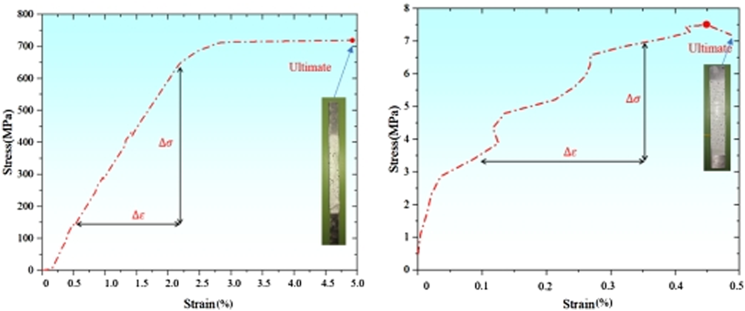
As shown in Figure 7(b), the transverse tensile strength (Y t ) is measured to be 7.5 MPa, with an elastic modulus (E 2 ) of 1.7 GPa. The manufacturer-reported values for the matrix direction are 15 MPa for tensile strength and 3.2 GPa for elastic modulus. It is evident that both properties decrease following the forming process. These results remain within a reasonable variation range. This reduction can be attributed to micro-defects such as voids and cracks, which interact with stress redistributions during tensile loading. This contrast reveals the inherent lower stiffness of the material in the 90° direction makes it more susceptible to effects from process or lay-up-induced inconsistencies, further amplifying the fluctuations observed in the stress–strain curve.
GF/PP compress performance
The experimentally measured compressive strength in the fiber direction (X
c
) is 127 MPa, which is lower than the value reported by the manufacturer for the prepreg material, as shown in Figure 8(a). Similar to the mechanism observed in the tensile tests, micro-defects may form at the fiber–matrix interface during the resin melting and curing stages of the winding process. These interfacial flaws are more likely to initiate localized damage under compressive loading, thereby reducing the overall compressive strength along the fiber direction. Nevertheless, the difference between the experimental result and the nominal value remains within an acceptable range and is consistent with the typical behavior of thermoplastic composites under compression. Notably, the presence of microstructural inhomogeneities introduced during the forming process may increase the randomness of damage initiation and propagation, leading to non-linear fluctuations in the stress–strain response. Such fluctuations are commonly observed in compression tests of composite materials and are considered reasonable. Stress-strain curve of GF/PP compress test (a) 0° (b) 90°.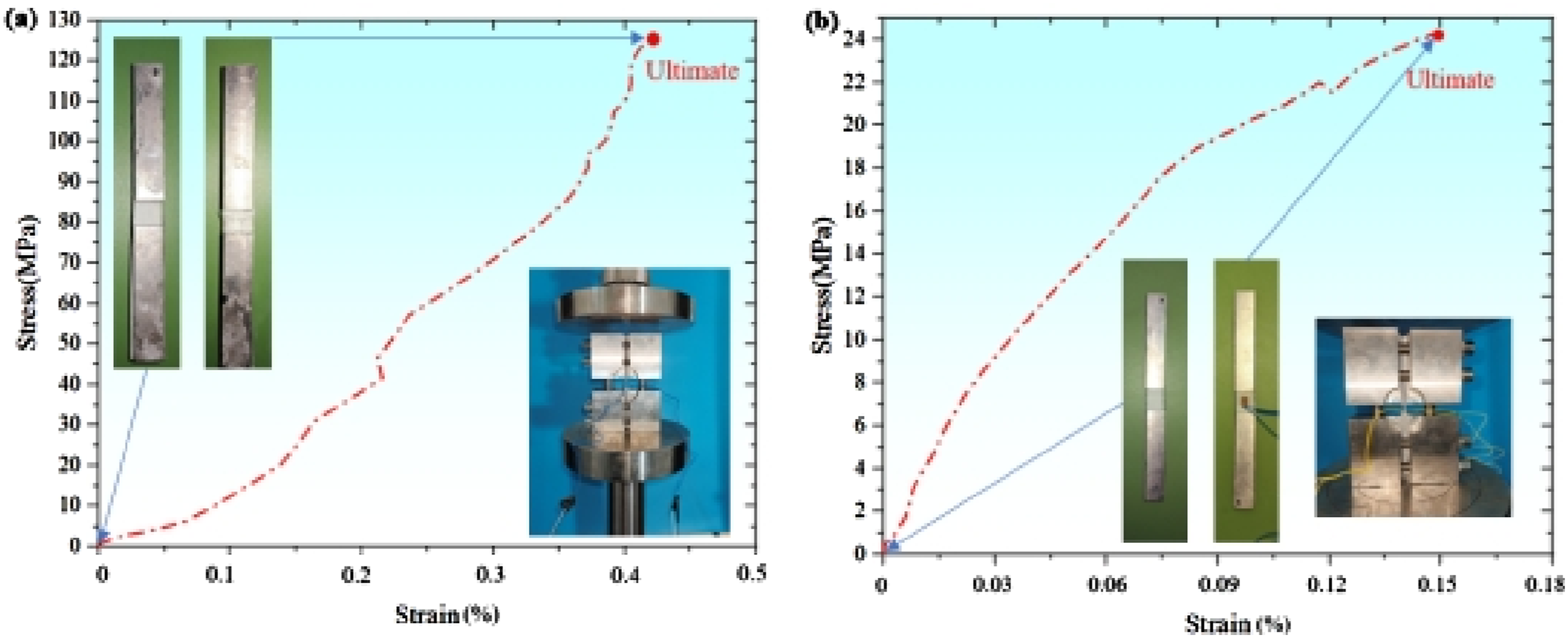
As shown in Figure 8(b), the transverse compressive strength (Y c ) is measured to be 24.2 MPa, compared to the manufacturer-provided value of 50 MPa. This reduction may result from non-uniform resin flow or excessive localized compaction during processing, which can thin the resin-rich layers and create areas of fiber crowding and resin accumulation, thus increasing the likelihood of local defects. In addition, residual stresses may be introduced into the matrix during high-temperature curing, making the material more susceptible to localized cracking under compressive loads and further reducing the effective compressive strength. These issues, associated with interfacial imperfections and local inhomogeneity, are within controllable limits and may be mitigated through process optimization in future automated manufacturing.
GF/PP shear performance
The shear behavior of GF/PP composites is illustrated in Figure 9. The measured in-plane shear strength S = 22.8 MPa and shear modulus G = 1.4 GPa. The parameters provided by the manufacturer are shear modulus 1.2 GPa and shear strength 20 MPa. Compared with the parameters provided by the manufacturer, the improvement of the shear performance of the material after processing is reasonable, reflecting the positive effect of the preparation process on the fiber/resin interface performance. Stress-strain curve of GF/PP tensile shear test.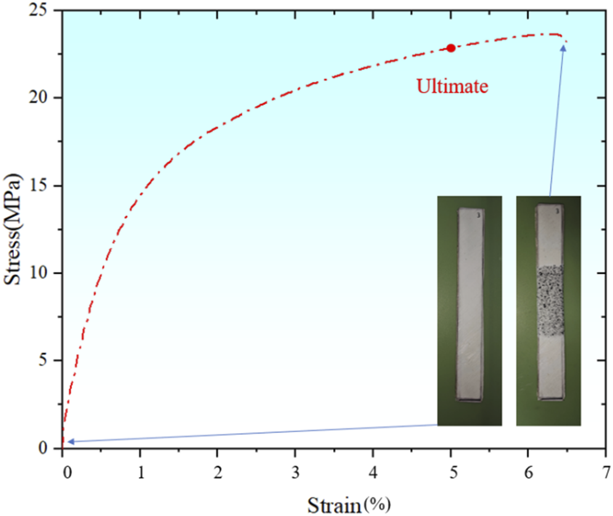
Tensile test of metal mesh
The metal mesh specimen had a gauge length of 50 mm and a width of 20 mm, and was treated as an equivalent continuous material with an effective cross-sectional area for stress calculation. The equivalent area was determined based on the measured wire diameter and the number of load-bearing wires within the gauge width, with void regions excluded, resulting in an effective cross-sectional area of 0.52 mm2. The load-displacement behavior of the specimen is shown in Figure 10. The load-displacement curve first shows the initial linear elastic deformation stage, where the load increases rapidly with the displacement and shows good linear characteristics, indicating that the metal mesh wire material shows high stiffness during initial loading; followed by the plastic deformation stage, where the load growth slows down, the curve shows nonlinear characteristics, the mesh wire undergoes plastic elongation and is accompanied by local yielding; finally, the failure stage, where the overall structure of the metal mesh is fractured and damaged. The curve trends are similar, but the fluctuations in the load peak and plastic stage are slightly different, which may be due to the initial defects in the mesh itself or the uneven strength of the local mesh wire. Load-displacement curve of metal mesh tensile test.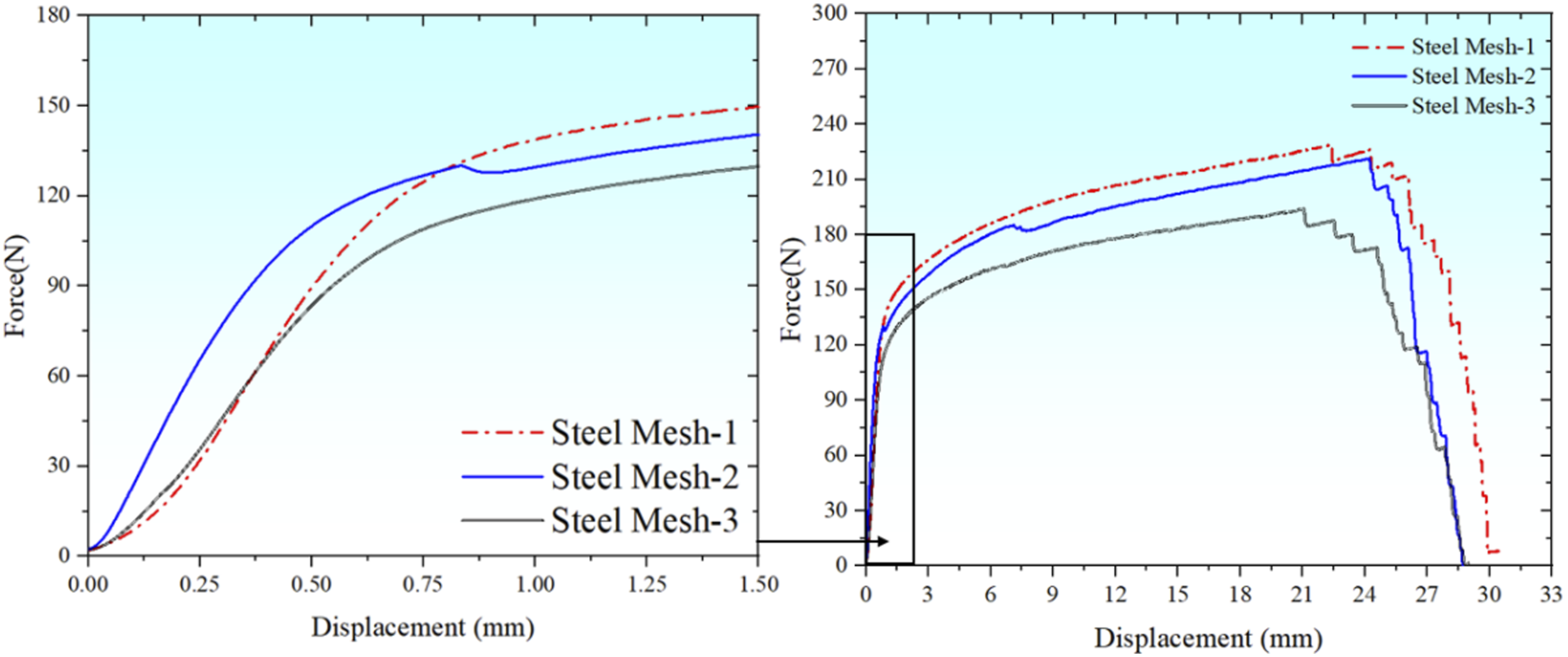
Conclusion
This study established a controllable fabrication route for metal mesh/GF/PP hybrid tubular structures and evaluated the mechanical behavior of their constituent materials under the same processing conditions. The main conclusions are summarized as follows. (1) A hybrid tube configuration consisting of inner and outer intertwined 45° GF/PP layers with an intermediate metal mesh was successfully fabricated on a 38 mm mandrel with a maximum length of 500 mm, ensuring stable geometry and uniform thickness. (2) The [45°/-45°/metal mesh/-45°/45°] lay-up combined with a roller-applied normal force of 40 N provided a balanced mechanical performance, which is attributed to improved interlayer contact, reduced void formation, and effective resin penetration into the mesh openings. (3) The mechanical properties of GF/PP laminates showed consistent trends with nominal manufacturer data, while variations in transverse and compressive performance were mainly caused by process-induced interfacial imperfections and local resin redistribution during heating and compaction. (4) The developed manual winding platform enabled controlled adjustment of winding angle, heating condition, and compaction force, demonstrating reliable fabrication repeatability and providing a practical basis for future laboratory-scale automated manufacturing.
This study helps bridge the missing links between processing parameters, structural characteristics, and constituent material properties in thermoplastic composite-metal hybrid tubes, and offers validated guidance for their structural design and fabrication in lightweight energy-absorbing applications.
Footnotes
Declaration of conflicting interests
The authors declared no potential conflicts of interest with respect to the research, authorship, and/or publication of this article.
Funding
The authors disclosed receipt of the following financial support for the research, authorship, and/or publication of this article: This work was supported by the CAST Young Elite Scientists Sponsorship Program; YESS20230429, National Natural Science Foundation of China; 12202088.