
Abstract
Joints are important connections for realizing long-distance transportation via composite pipes and have been widely used in oil and gas transportation. A joint is also a weak link influencing the safe operation of pipelines. In this work, a three-dimensional assembly model of glass fiber-reinforced plastic composite pipes and metal buckling joints was constructed and analyzed using the finite element method (FEM) to investigate the influence of the buckling amount and structural parameters of joints on the sealing performance of joints. The results showed that the sealing performance of the joint gradually improved with increasing buckling. When a larger amount of buckling occurs, the RTP will undergo excessive plastic deformation, and the sealing performance of the joint decreases. The optimized structural parameters of the metal joint are a buckling amount of 5 mm, several serrations of 13, a tooth height of 3 mm, and two serration angles of 55° and 25°. When using optimized parameters and extreme working conditions (the internal pressure is 19.2 MPa), the maximum stress of the innermost fiber exceeds the tensile strength with a higher risk of failure. However, the optimized design of the joint can meet the requirement of safe operation at a standard pressure of 6.4 MPa.
Keywords
Introduction
The global consumption of oil and gas resources is increasing rapidly. However, the production and consumption of oil and gas resources are very inconsistent, which makes pipelines suitable for long-distance transportation a major need for oil and gas socioeconomic operation. To improve transportation efficiency, the design and usage of pipelines are trending toward high pressure, large diameter, automation, and intelligence.1,2
Oil and gas transportation pipelines are divided into two categories: steel pipes and flexible composite pipes. Steel pipelines have been widely used in the past decades due to their high 1 strength and good connectivity. However, steel pipelines have the disadvantages of corrosion, high frictional resistance of the inner wall, and low ductility.3,4
In recent years, nonmetallic flexible pipelines have partially or completely replaced traditional steel pipelines in some fields due to their remarkable features, such as good corrosion resistance, high flexibility, designability, long service life, and ease of laying and recycling. In particular, reinforced thermoplastic pipes (RTPs) are widely used in the petroleum industry.5,6 RTP pipelines are generally composed of a three-layer structure, including a liner layer, reinforcing layers, and outer protective layer, as shown in Figure 1. Among those layers, the inner and outer layers are mostly polyethylene, and the reinforcing layer is made of helically wrapped fibers, such as steel wire, steel belts, glass fibers, and aramid fibers. This multilayer fiber structure bears most of the loads in the pipe.7,8 Structural diagram of RTP.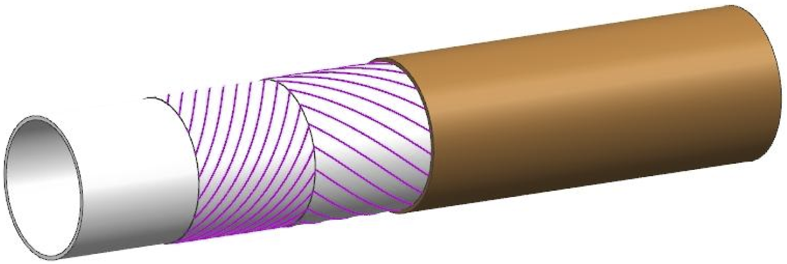
A pipe joint is an important part of a flexible composite pipeline for oil and gas transportation systems; this joint is the end fitting of flexible composite pipes and connects and seals pipelines. Stress concentration will likely occur between the composite pipe and the joint, which will easily lead to failure or leakage at the joint and the composite pipe connection. Therefore, a reasonable design is highly important for ensuring the safety of oil and gas development.9,10
There are two main mechanical joint types for RTP pipes: electrofusion joints and metal buckle-type mechanical joints. Two pipes, which are made of polyethylene materials, are welded by electric heating of sleeve fittings, as shown in Figure 2. The preembedded resistance wire is set in the inner wall of the sleeve. The inner diameter of the sleeve is equal to the outer diameter of the connected pipes, which can be inserted into the electrofusion sleeve on both sides. When electricly heated, the sleeve wall is welded to the outer wall of the pipe of the polyethylene material, and the joint is finished after cooling.11,12 The outstanding advantages of electrofusion connections include corrosion resistance and poor leakageability. Because the welding voltage and time are controlled by the welder, the connection process is less affected by human factors, which can result in high production efficiency.
13
However, due to the load capacity, an electrofusion joint cannot be applied at high pressure. Flow of the electrofusion joining process.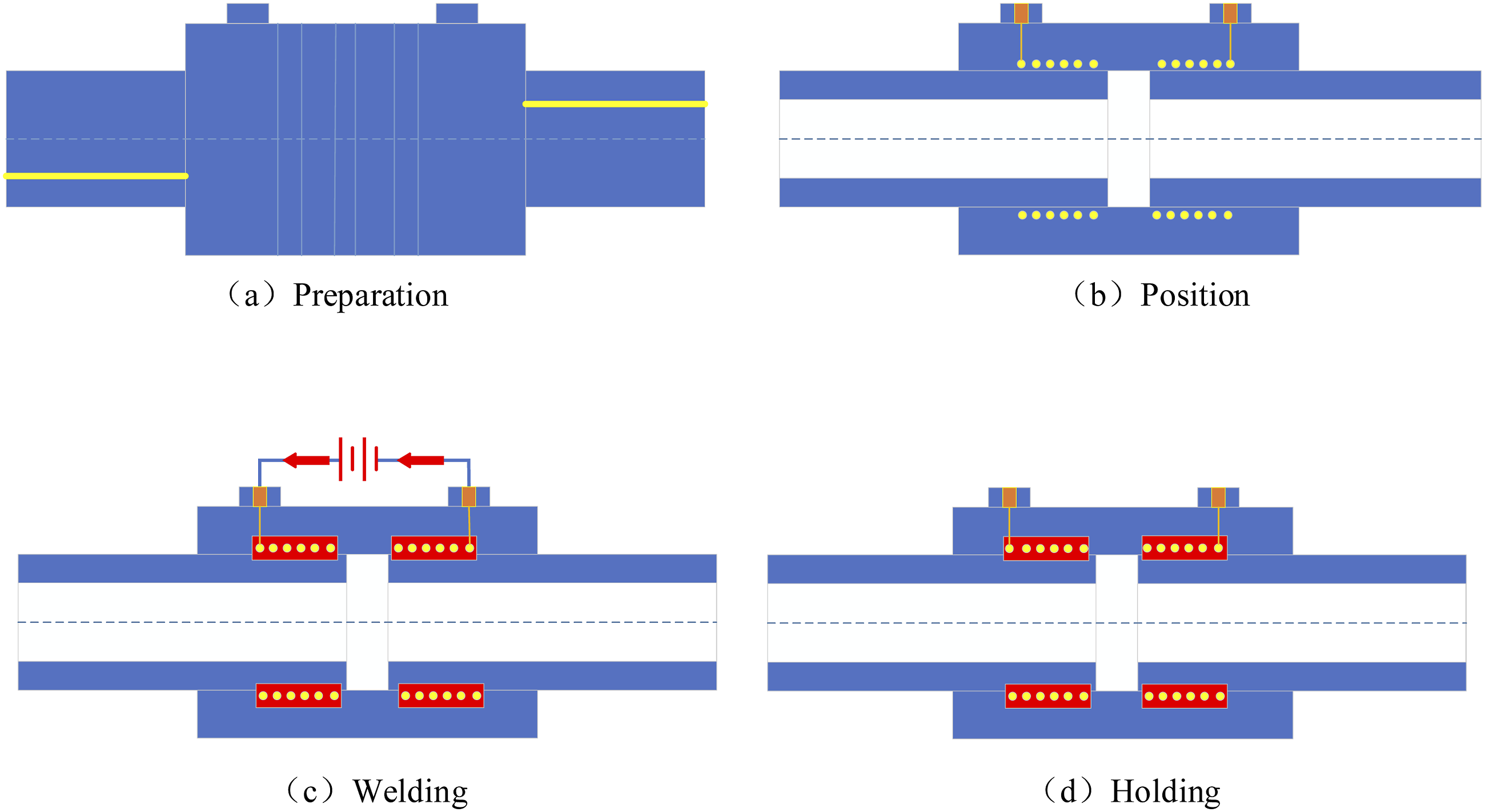
In the metal buckling connection, the socket end of a metal pipe fitting into the inner side of the RTP pipe is inserted, and a metal sleeve is placed on the outer side of the RTP pipe. By pressing the metal sleeve to yield, a joint is formed to ensure sealing and withstand axial loads. Then, the metal pipe fittings are connected by flanges. The structure of the metal buckling joint and its fittings are shown in Figure 3. Metal buckling joints are simple, easy to install, and suitable for construction sites with complex terrains. However, there are two disadvantages to this approach. First, to press the end of the RTP pipe and metal buckling fittings firmly, enough pressure must be applied to the sleeve and the RTP pipe. After enduring a large force over a long time, the polymer material will enter the creep state, resulting in a gradual decrease in the compression force and a loose-fitting joint. Second, metal buckling fittings are generally made of stainless steel or carbon steel through the mold forging process, and the manufacturing cost is high. Swaged fitting for connecting RTPs.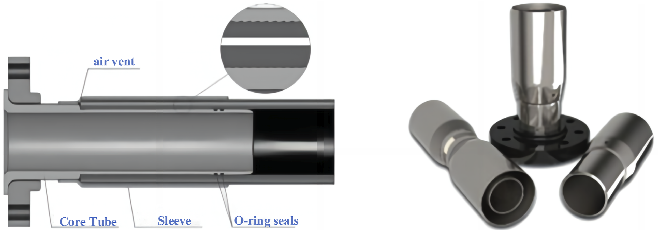
In addition to design and manufacturing issues, most related research has focused on the service performance of RTPs and their joints through different methods of theoretical analysis and numerical simulation.14,15 Based on differential equations and boundary conditions, analytical methods are used to theoretically determine the stress model of the composite pipe and joint. Research on composite pipes has involved four main types of composite pipes reinforced with different fibers: aramid fibers, carbon fibers, glass fibers, and steel wires. Based on three-dimensional isotropic elasticity theory, Xia, et al.16,17 investigated the mechanical properties of aramid fiber-reinforced composite pipes under internal pressure loading and derived an analytic solution for stress, which introduced thermomechanical parameters into the theoretical model and investigated the effect of temperature on the performance of RTPs. Bai, et al. 18 established a two-dimensional theoretical model of RTP, which was used to calculate the pressure vs axial strain relationship under tensile and compressive loading. Additionally, finite element analysis was used to investigate the mechanical behavior of aramid fiber-lined pipes, which were used to repair damaged steel pipes. 19 Kobayashi, et al. 20 proposed an elastoplastic model for carbon fiber composite pipes and calculated the stress‒strain distribution of the pipe wall. Moreover, the bursting stress of the pipe was determined by the maximum strain criterion, which is similar to the results from the finite element model. Zheng et al.21,22 investigated the short-term mechanical properties of steel wire-entangled reinforced composite pipes under internal compressive loading, simplified the reinforcing layer into an outer square and inner circle model, derived the elasticity parameter of the reinforcing layer in all directions, and obtained the stress‒strain relationship between the two layers of the composite layer. Based on the limit state equation, Patil, et al. 23 derived the equations for the bearing capacity of a pipe under various combinations of loads for rapid estimation of its mechanical performance. For thick-walled pipes, the difference in the results between the equations and the finite element model is less than 4%, while the corresponding value is within 2% for thin-walled pipes.
Since theoretical models are extremely complex when considering material nonlinearities, finite element models are often used for high-fidelity analysis. Hasegawa, et al. 24 used finite element methods to analyze the failure loads of pipes with cracks extending in the circumferential direction under torsional and bending loads and described an equivalent bending moment calculation method for initial defect assessment. Yu, et al. 25 studied the mechanical properties of RTP under combined loads of external compression and bending by using the finite element method, and the nonlinear properties of PE and reinforcing layers were edited by the subroutine UMAT and imported into ABAQUS software so that the model could accurately simulate the buckling of the pipeline and the change in the pipe’s cross-sectional shape after buckling. performed a sensitivity analysis Yu, et al.25,26 and revealed that the buckling mechanism of a pipe is related to the loading sequence and that the critical torsion angle decreases rapidly with increasing external pressure. Therefore, greater pressure will significantly reduce the bending performance of the pipeline.
Pipe joints are more complex structurally 27 and cannot be analyzed theoretically. The FEM is more suitable for studying this topic. Mansouri and Tavallali 28 developed two approximate transient heat transfer models to simulate thermal pulsations in joints for electrofusion joints. In this research, the heat source term was introduced as a new geometric coefficient to calculate the thermal efficiency of the joints. Shi, et al. 29 conducted a comprehensive study of defects and failure modes for electrofusion joints. Xinyu, et al. 30 presented the principles of electrically fused joints, the temperature distribution, and the distribution of stresses due to thermal and structural loading. Due to special loading conditions, the inner cold region of the electrofusion joint has a highly stress-concentrated area. Finite element analysis revealed that an increase in the internal pressure leads to an increase in the gap between the pipe and the joint, while the thermal load and external pressure counteract the stripping effect. Liu, et al. 31 determined the key design parameters of an electrofusion joint based on the median diameter formula in elastic theory and established a finite element model of the joint to analyze the stress distribution of the joint under ultimate internal pressure. Das and Pradhan 32 discussed the finite element analysis of bonded tubular socket joints fabricated with laminated fiber-reinforced plastic composite structures, and the effective lap lengths suitable for the performance of the joints were determined based on the Tsai–Wu failure criterion. The stresses were concentrated at the free edges of the coupling region of the bonded TSJs and near the adhesive junction. Abid, et al.33,34 investigated the strength and sealing performance of gasket bolted flanged pipe joints under bolted and combined operating conditions via three-dimensional nonlinear finite element analysis. It was concluded that the strength of the joint was affected by the combination of axial and thermal loads, while the sealing of the joint depended on the bolting strategy during assembly. The thermal load had a significant effect on the sealing performance, which could not be effectively sealed above 100°C, increasing the risk of overall joint failure. Nimje and Panigrahi 35 used the strength of materials method to determine the critical position of socket joints and analyzed laminates using the principle of fracture mechanics. The failure evolution of functionally graded bonded socket joints for FRP composite pipes and the fracture behavior of embedded failures were analyzed using the principle of fracture mechanics.
Although there are many studies on the connection performance of different types of mechanical joints, most of them have concentrated on electrofusion joints, and few have focused on the connection performance of metal buckle-type mechanical joints. The metal buckle-type mechanical joint involves the plasticity of metallic materials and the nonlinear contact of metallic/nonmetallic parts. Therefore, the analytic model is more difficult. Therefore, in this paper, the finite element method (FEM) is used to establish a three-dimensional overall assembly model of glass fiber-reinforced plastic composite pipes and metal buckle-type mechanical joints to determine the optimal buckling amount of the mechanical joint and the main structural parameters of the joint, such as the serration angle, number of teeth, and tooth height, on the sealing performance of the joints. The optimal structural parameters of the metal buckle-type mechanical joint are obtained to guide the design of the mechanical joints of the RTP pipe.
Finite element modeling and validation
Modeling
Material parameters and modeling of RTP joints
In this paper, Figure 4 shows the glass fiber-reinforced thermoplastic pipe (GFRTP) and buckling joint with a size of DN150/PN6.4 MPa. The GFRTP consists of three layers of material, namely, the inner liner layer, the fiber-reinforced layer, and the outer protective layer, as shown in Figure 5. The joint is composed of two core tubes, two sleeves, and a connecting bolt. By buckling the sleeve to squeeze the RTP, the inner and outer surfaces of the RTP will be deformed to fill the gap in the annular serration on the joint, realizing connection and sealing, as shown in Figure 6. According to the principle of buckling connection, the structural parameters of the serration directly affect the sealing performance of the fitting, as shown in Figure 7. Assembly relations of Buckle Fittings for connecting RTPs. Design dimensions of RTP. Main components of buckle fittings for connecting RTPs. Detailed geometry of the serrated tooth.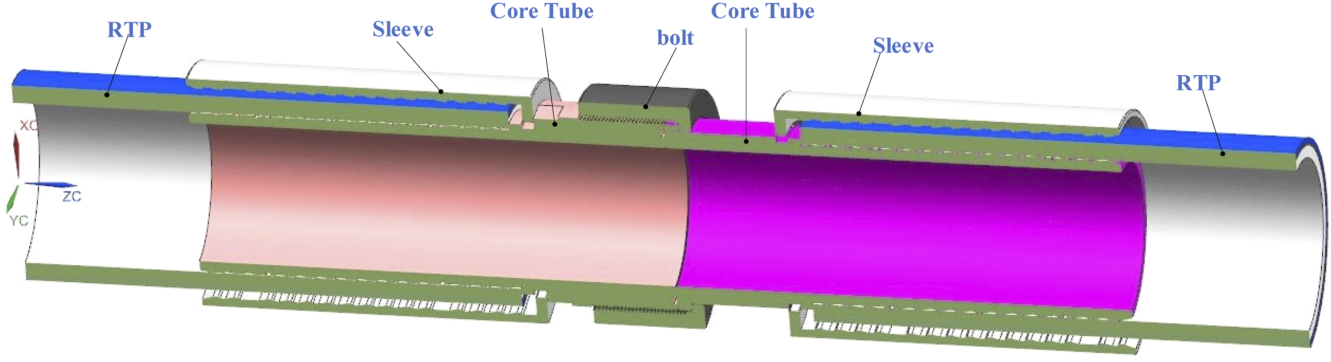
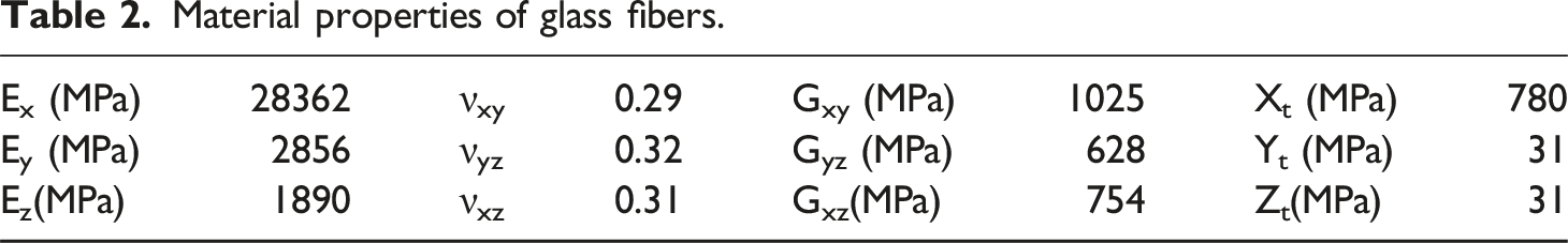
Material properties of the GFTRP and joint.
Material properties of glass fibers.
Using ANSYS 2021R1 software, the RTP joint is meshed and modeled with an ANSYS/ACP composite material module. According to the actual usage process, a geometric assembly model including a composite pipe and joints is formed for building the finite element model, as shown in Figure 8. Finite element model of buckle fittings.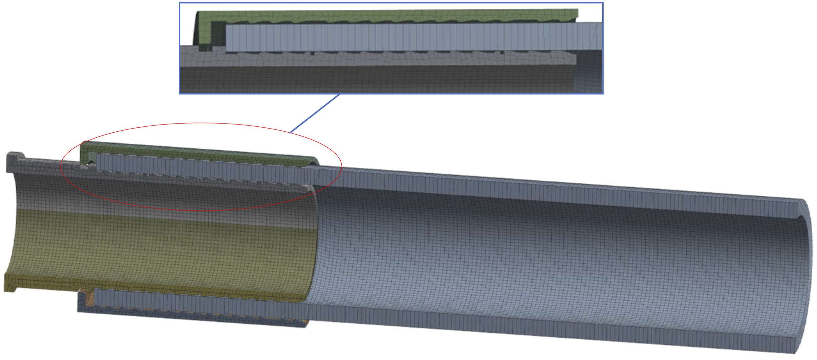
Boundary conditions and loads
In the finite element model, surface-to-surface contact is set in the region of interaction between the metal joint and the RTPs, with the metal joint serving as the master surface and the tube body serving as the slave surface. The tangential behavior is based on the friction formulation of the penalty function with a friction coefficient of 0.25.
To simulate the buckling process of the joint and the sealing performance, boundary conditions and loads must be applied to the finite element model. Reference points are established at the right end of the RTP and the left center of the core tube, and the respective end surfaces are coupled to the reference point. The reference point belonging to the core tube is completely fixed, and the RTP point is constrained with five degrees of freedom and is free only in the axial direction (Z-axis).
Two general static analysis steps were established for simulation: the first was the buckling assembly, and the second was the loading of internal pressure. In the buckling analysis step, a radial displacement is applied on the outer surface of the sleeve to press it and RTP together. After that, an internal pressure of 6.4 MPa was applied to the inner surface of the pipe and the joint. Since an axial pullout force exists under an internal pressure load, it is also necessary to apply an axial force at the reference point of the RTP with the functional expression F = 0.25πD2P, where D is the internal diameter of the RTP and P is the internal pressure. The applied constraints and loads are shown in Figure 9. Boundary conditions and loads applied on the finite element model of the RTP joint.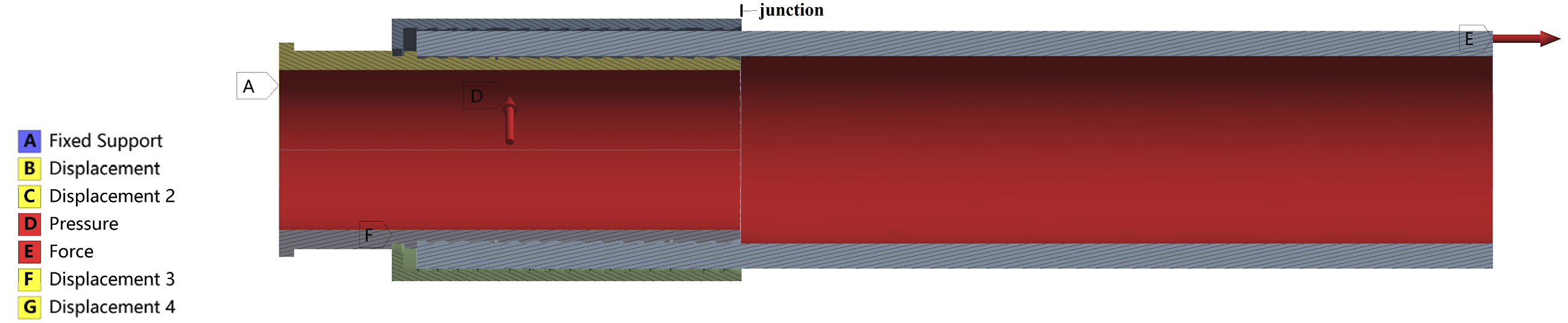
Model Validation
The strength analysis of the GFRTP joint was conducted under an internal pressure of 19.2 MPa (3 times the standard internal pressure, 3 × 6.4 MPa) and an external buckling value of 5 mm. At the same time, the axial pull-out force generated under the internal pressure load is 339 kN.
The metal parts in the GFRTP joints have a strong bearing capacity and generally will not be damaged. When subjected to an internal pressure load, the stress in the fiber-reinforced layer is much greater than that in the inner and outer protective layers. Furthermore, for different fiber layers, the stress in the innermost layer is always greater than that in the outermost layer, which is more likely to fail. Therefore, the von Mises stress of the innermost fiber layer is used as the basis for judging the failure of the GFRTP joints. The strength of each part under the above loads and constraints will be analyzed below.
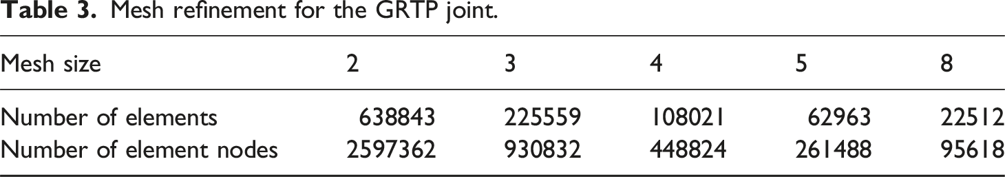
Mesh refinement for the GRTP joint.
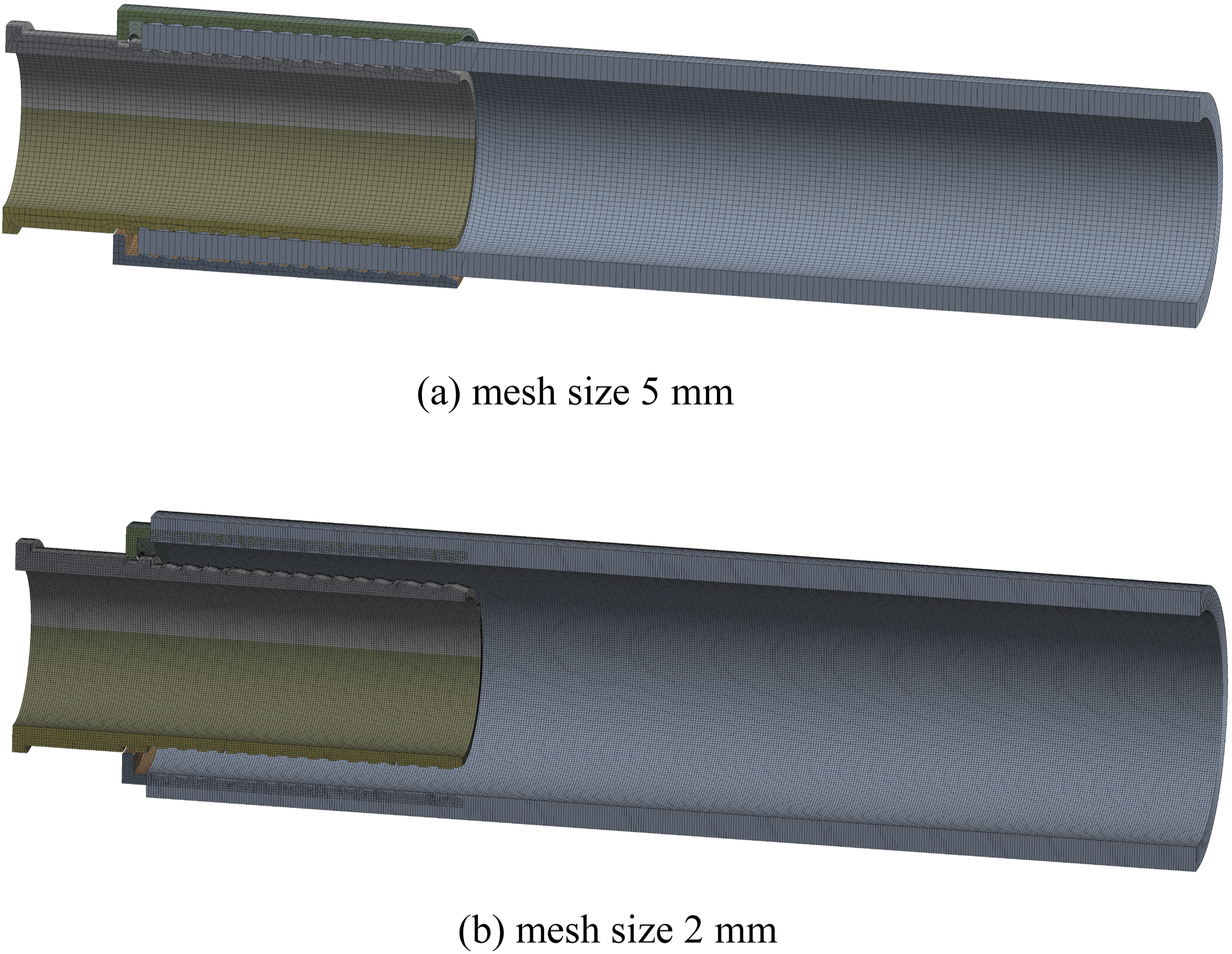
Comparsion of mesh model for different meshing desnsity.
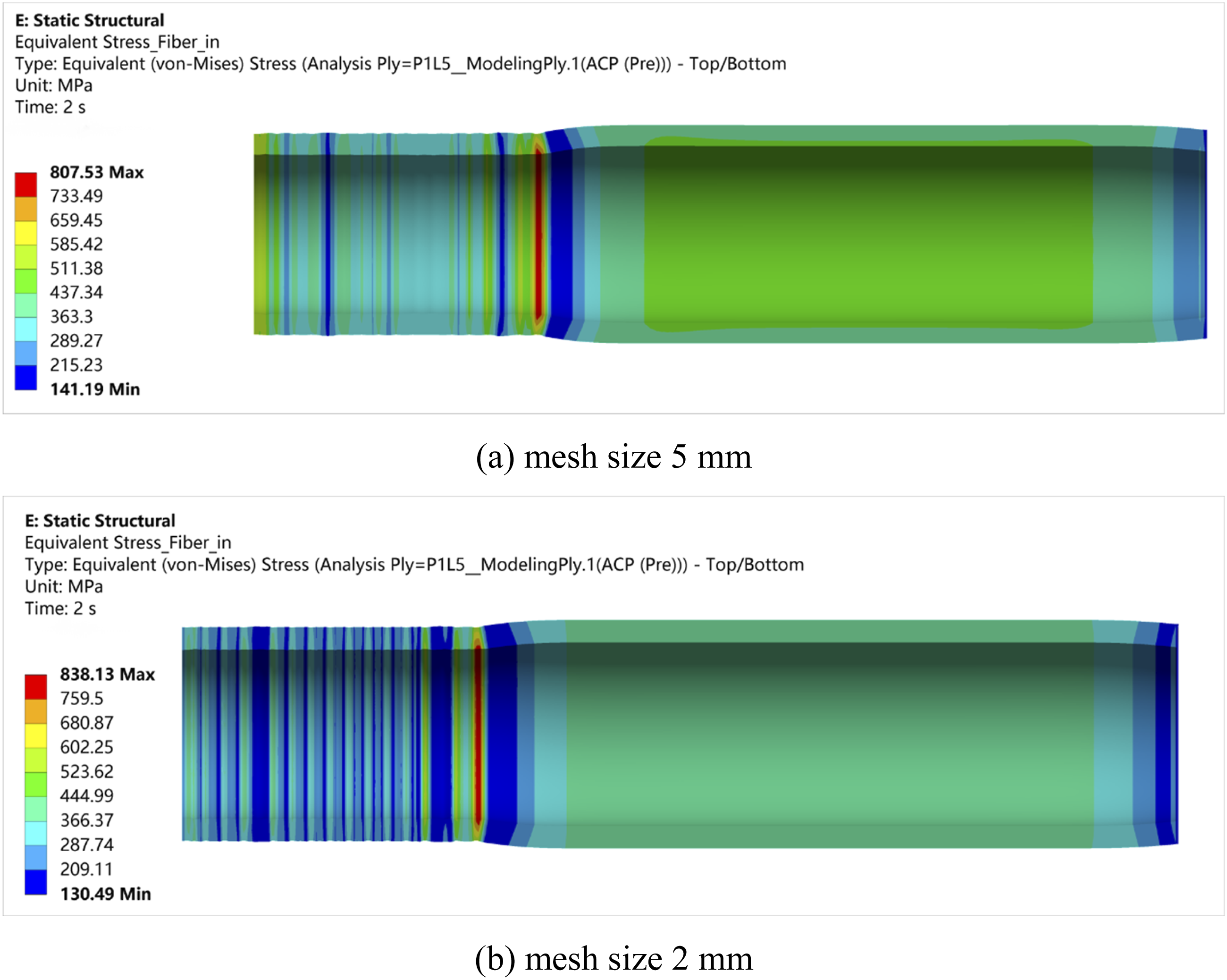
Stress distribution of the innermost fiber layer for different mesh size.
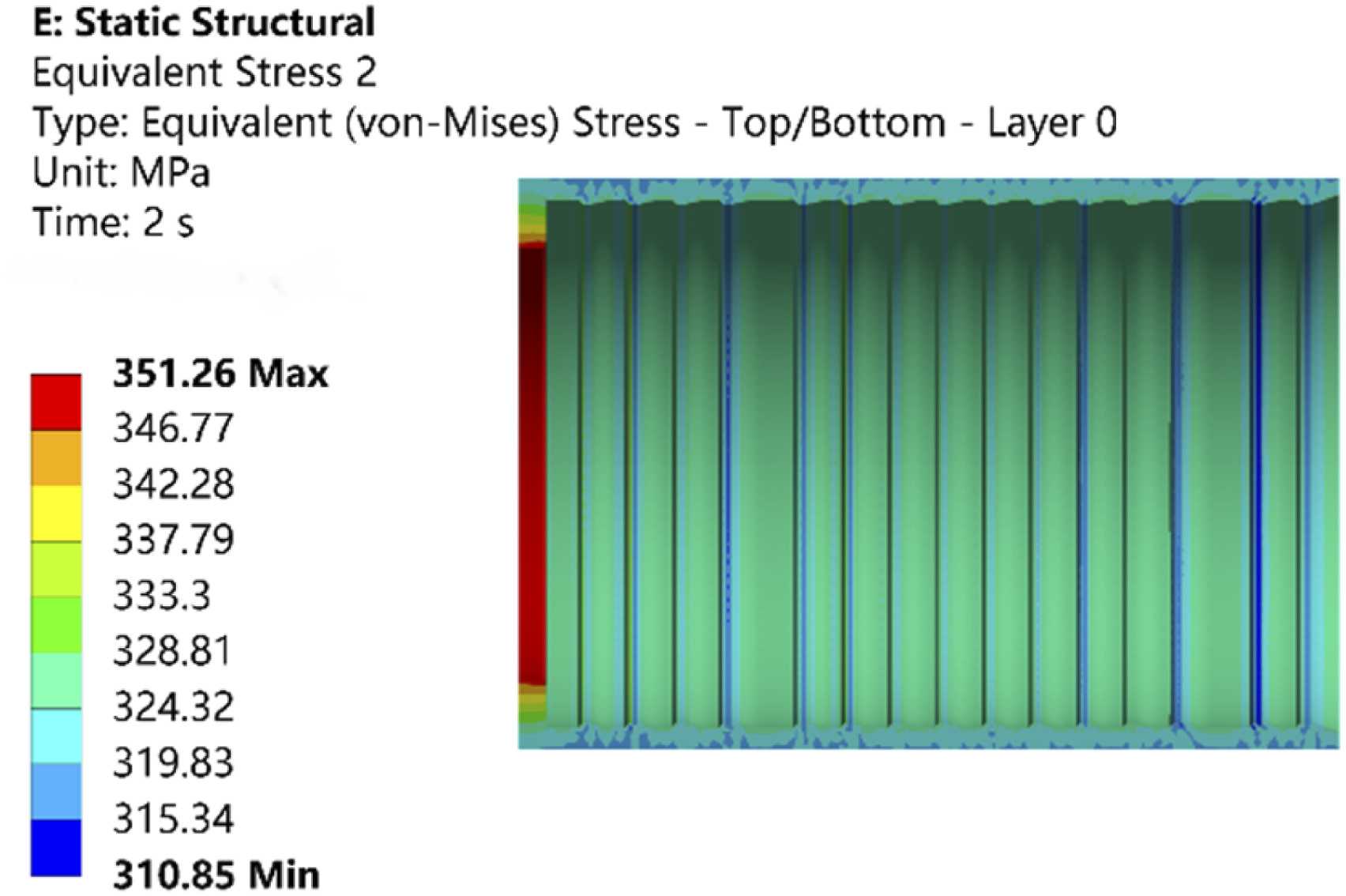
Figure 12 shows the radial deformation of the GFRTP joint. When the buckling amount (BA) is 5 mm, the total radial deformation of the sleeve reaches 5.6 mm, which is close to the maximum allowable buckling amount of 6 mm. Figures 13 and 14 show the maximum stresses of the sleeve and the core tube, which are 351 MPa and 286 MPa, respectively, indicating that both have exceeded the yield strength, which is necessary for buckling. Figure 15 shows the maximum stresses and strains of the GFRTP in the vicinity of the junction, indicating that the highest stress occurs in the outermost fiber layer, with a peak of 838 MPa, which is slightly greater than the yield strength of glass fiber 830 MPa. It is also predicted that stress concentration in the vicinity of the junction is more likely to occur, causing fiber fracture. This phenomenon is also verified by the burst test result shown in Figure 16, which illustrates that the burst location is the same as that from the FEM. For HDPE, the strain is properly adopted as the failure criterion. As shown in Figure 15, the strains of the liner and cover are less than 5%, which is considered the maximum allowable strain of PE.
36
Overall, the internal pressure of 19.2 MPa is close to the bearing capacity limit. Radial deformation of the GFRTP joint. Stress of sleeve. Stress of core tube. Stresses and strains of the GFRTP. Burst failure of the GFRTP joint from test.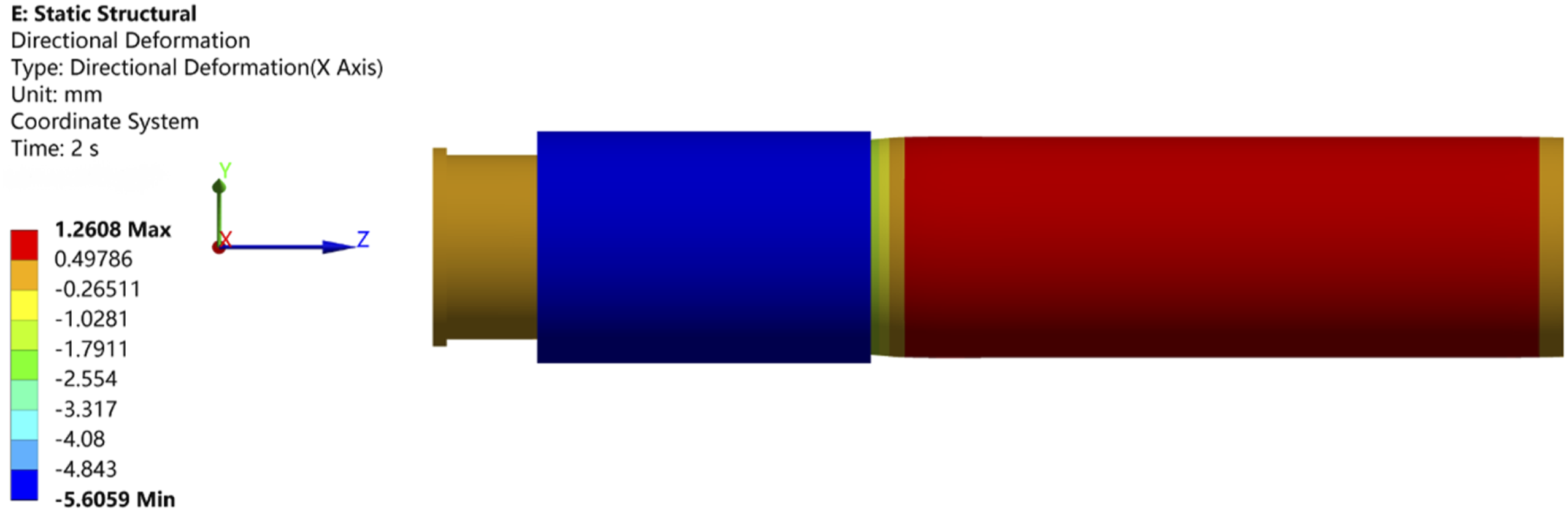
Optimization of the design parameters for the GFRTP Joint
Optimization of the buckling amount
The buckling pressure is necessary for the buckling process and has a direct effect on the sealing performance of the joint. Therefore, first, the optimal amount of buckling needed to improve the sealing performance was determined. In this paper, different buckling amounts (3∼6 mm) are applied on the surface of the sleeve to analyze the contact pressure distribution and sealing performance of the GFRTP joint under a standard internal pressure of 6.4 MPa. The optimized buckling amounts can be determined by investigating the maximum contact pressure, contact area, and frictional stress.
Figure 17 shows the stress distributions of the GFRTP and joints for different buckling amounts. When the buckling amount reaches 3 mm, the maximum equivalent stress of the sleeve is 308 MPa, which is greater than the yield strength of 316 L steel (240 MPa). This indicates that plastic deformation occurs on the sleeve. The contact pressure peak between the sleeve is greater than the internal pressure of 6.4 MPa. A similar situation occurs with the contact pressure between the GFRTP and the core tube. It can be inferred that the GFRTP joint is efficient and provides a certain degree of sealing to realize the connection. When the buckling amount is 6 mm, the stress on the sleeve exceeds the yield strength of the material. The stresses on the liner, outer protective layer, and reinforcement layers did not exceed the corresponding yield strengths. However, the stress on the reinforcement layer is 767 MPa, which is close to the tensile strength of the fiberglass 780 MPa. The radial deformation of the sleeve is 6.7 mm, which is greater than the allowable distance of 6 mm limited by the difference in the radii of the sleeve flange and the core tube slot. Therefore, excessive buckling can lead to excessive contact stress between the sleeve clamping flange and the core tube groove and harm the performance of the joint. It is reasonable that the buckling amount should not reach or exceed 6 mm. Stress distribution for RTP joint.
In summary, the buckling amount of the sleeve is between 3 mm and 6 mm. In the following, the effect of contact pressure on the serration of the sleeve and core tube is analyzed using different buckling amounts, as shown in Figure 18. The pressure is greater at the top of the serration and decreases at the bottom of the serration. However, at this time, the pressure is still much greater than the internal pressure to ensure effective sealing performance. As the amount of buckling increases, the contact pressure of the serration also increases. If the buckling amount is too small, the GFRTP will detach from the joint or leakage occurs during use because of the pull-off force generated by the internal pressure. In other words, if the buckling amount is too large, GFRTP damage and failure are likely to occur. Effect of crimping values on contact pressure in RTP joint.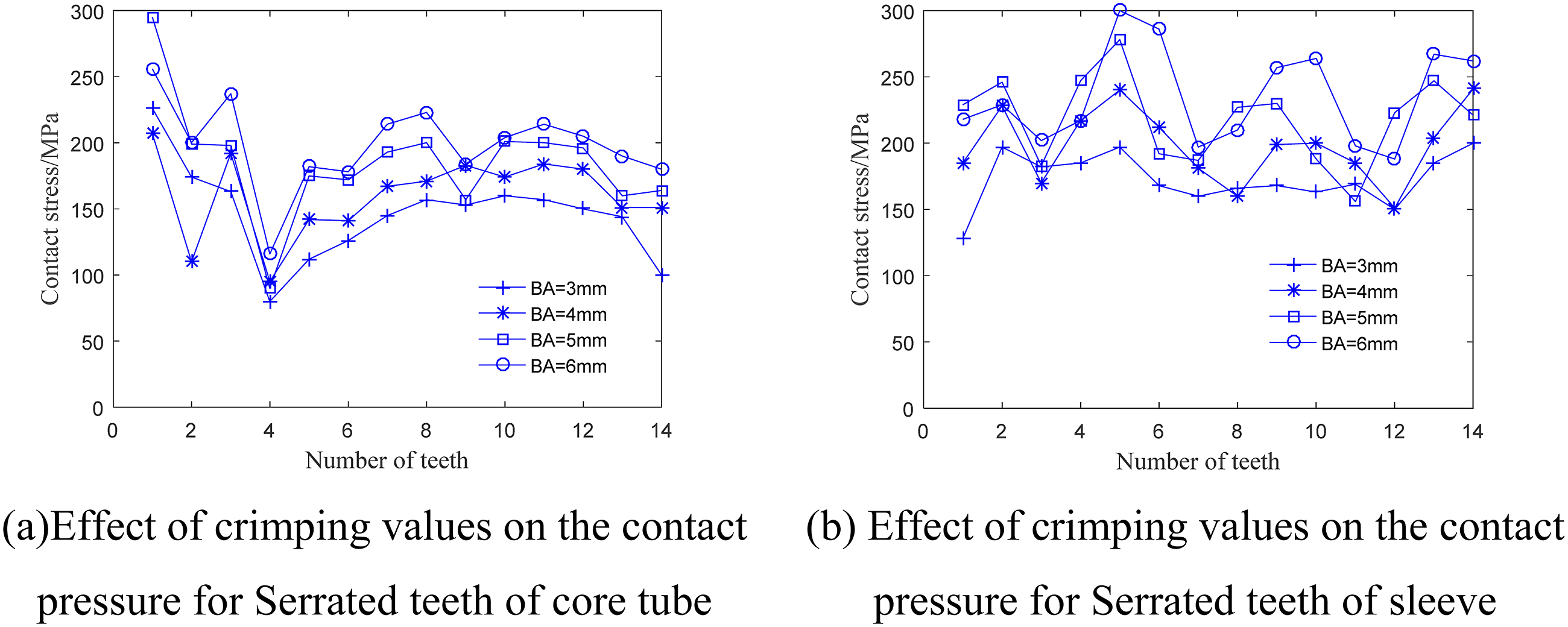
The ratio of the contact area to the nominal surface area also has an important effect on the sealing performance of the GFRTP joint. Figure 19 shows the contact area ratio for different buckling amounts. The contact area ratio increases with increasing buckling amount, and the sealing performance improves correspondingly. When the buckling amount is 3 mm or 4 mm, the percentage of contact area is small. Accordingly, the optimal buckling amount is 5∼5.5 mm when the internal pressure is 6.4 MPa, and the buckling amount should be adjusted according to the different internal pressures. Ratio of real contact area to nominal surface area in RTP joint for different crimping values.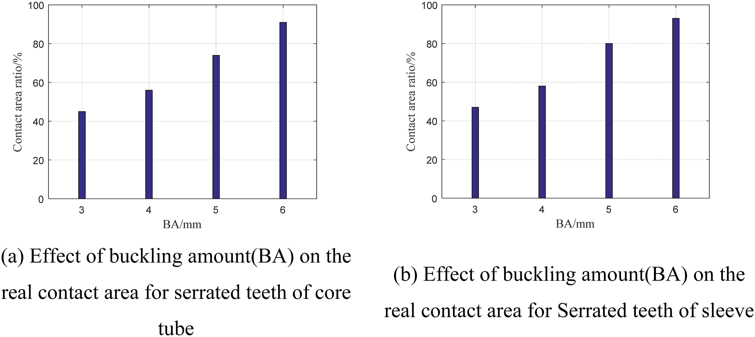
Optimization of joint structure parameters
The performance of GFRTP joints is closely related to the structural parameters of the serrations belonging to the sleeve and core pipe. Therefore, the serration is geometrically parameterized, as shown in Figure 20; namely, the number of teeth N, the height of the teeth h, and the bevel angles on both sides are θ1 and θ2. The value of N ranges from 12 to 16. The values of h are listed as 1 mm, 1.5 mm, 2 mm, 2.5 mm, and 3 mm. The value of θ1 ranges from 30° to 80°. The value of θ2 ranges from 5° to 40°. Then, with the FEM model, the performance of the GFRTP joint is studied to analyze the influence of the serration parameters on sealing and to determine the optimal joint structure. Definition of parameters for joint serration.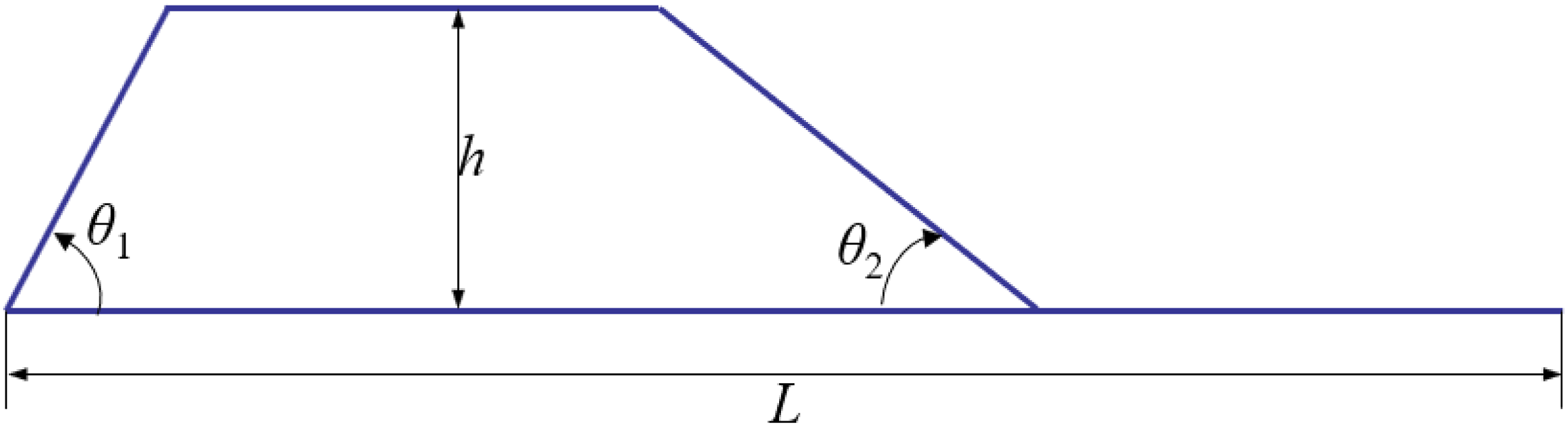
Figure 21 shows the effects of different numbers of teeth, contact pressures, and contact area ratios for the sleeve under an internal pressure of 6.4 MPa. The contact area ratio does not change much with an increase in the number of serration teeth. The maximum contact stress increases and then decreases with the number of serration teeth and reaches the maximum value of 252 MPa when the number of teeth is 13. Because of the greater contact pressure, sealing and connection are more reliable. However, when the number of teeth is 16, the number of serration teeth is too high, and there is not enough space to accommodate the plastic deformation of the GFRTP. Therefore, a compromise between the maximum contact stress and contact area ratio is considered, and the optimal tooth number is initially determined to be 13. So it makes the balance between strength and machinability. Effect of the number of serrated teeth on contact and sealing of sleeves in the RTP joint.
Figure 22 shows the effects of the height of the serrations on the maximum contact pressure and contact area ratio. As the tooth height increases, the maximum contact pressure and contact area ratio increase. This indicates that the compression between the GFRTP and sleeve also increases with increasing tooth height. However, if the tooth height is too large, the deformation of the GFRTP is transmitted to the core tube, resulting in greater deformation and ineffectual connection. Therefore, considering the contact area ratio and stress of the joint, the optimal tooth height is determined to be 3 mm, which can ensures no slippage or peeling under pressure, effectively preventing leakage. Effect of the serrated tooth height on contact and sealing of sleeves in the RTP joint.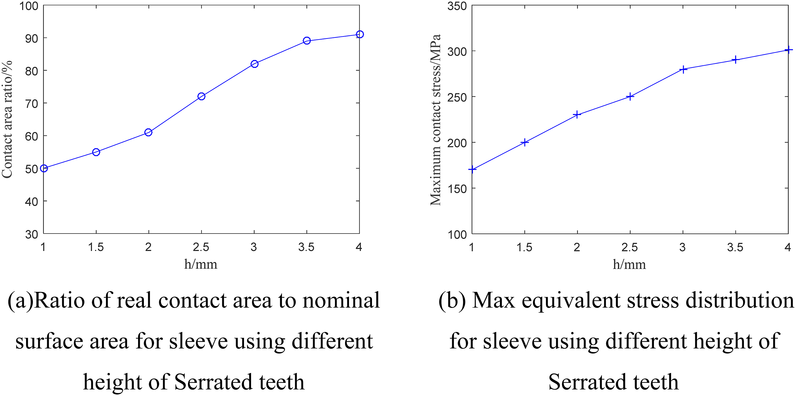
Figure 23 shows the effect of the bevel angle θ1 of the serrations on the contact pressure and area ratio. The maximum contact pressure and area ratio both increase with increasing θ1. The contact area ratio reaches the maximum value when θ1 is 60°, the maximum contact pressure reaches the maximum value when the serrated angle θ1 is 50°, and the percentage of contact area reaches the maximum value. Therefore, considering the influence of sealing performance and pipe strength, the serration angle θ1 can be taken between 50° and 60°. This angle is relatively large, enhancing the strength of the joint and preventing the pipe from being pulled apart under high pressure. Effect of different angle θ1 on contact and sealing for sleeve in GRTP joint.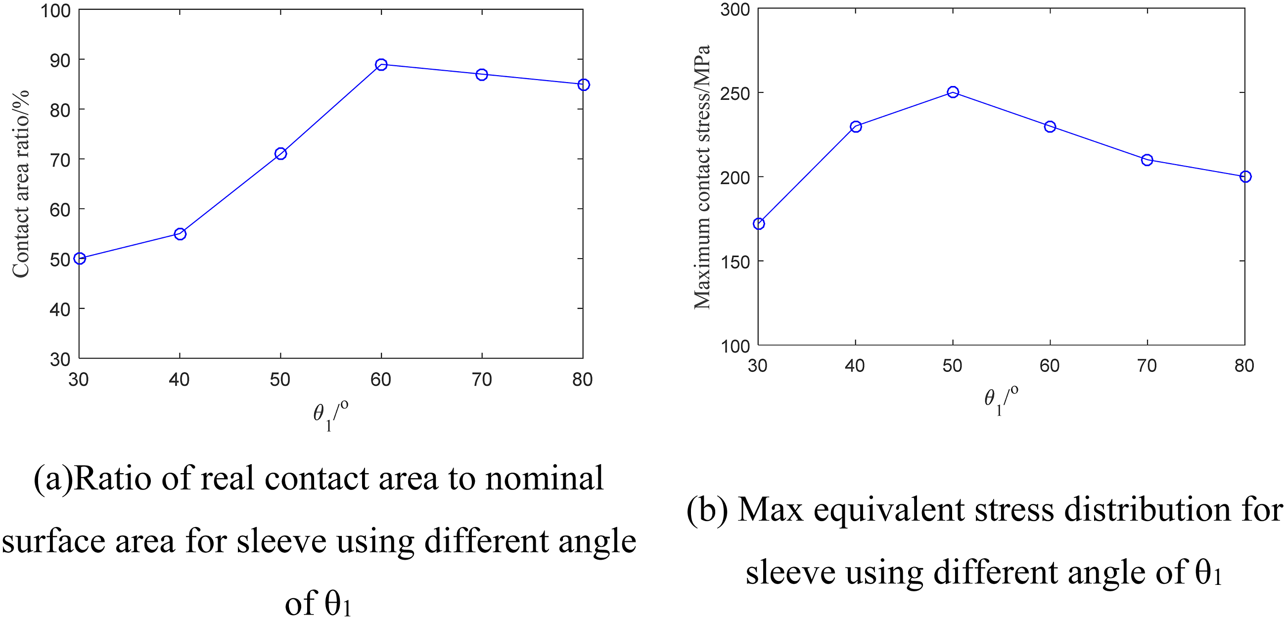
Figure 24 shows the effect of the serration angle θ2 on the contact pressure versus the sealing area. Since θ2 is on the outer side of the serration, a smaller θ2 facilitates the entry of the composite tube, so its value should not be too large. With increasing θ2, the maximum contact pressure and effective sealing area both increase, and the maximum contact pressure reaches the maximum value when the serration angle θ2 is 20°. The maximum contact pressure reaches the maximum value when the sawtooth angle θ2 is 30°, and the percentage of contact area reaches the maximum value. Therefore, considering the influence of sealing performance and pipe strength, the corrugated serration angle θ2 can be taken between 20° and 30°. This angle is relatively small, which helps reduce assembly resistance and facilitates construction and installation. Effect of different angle θ2 on contact and sealing for sleeve in GRTP joint.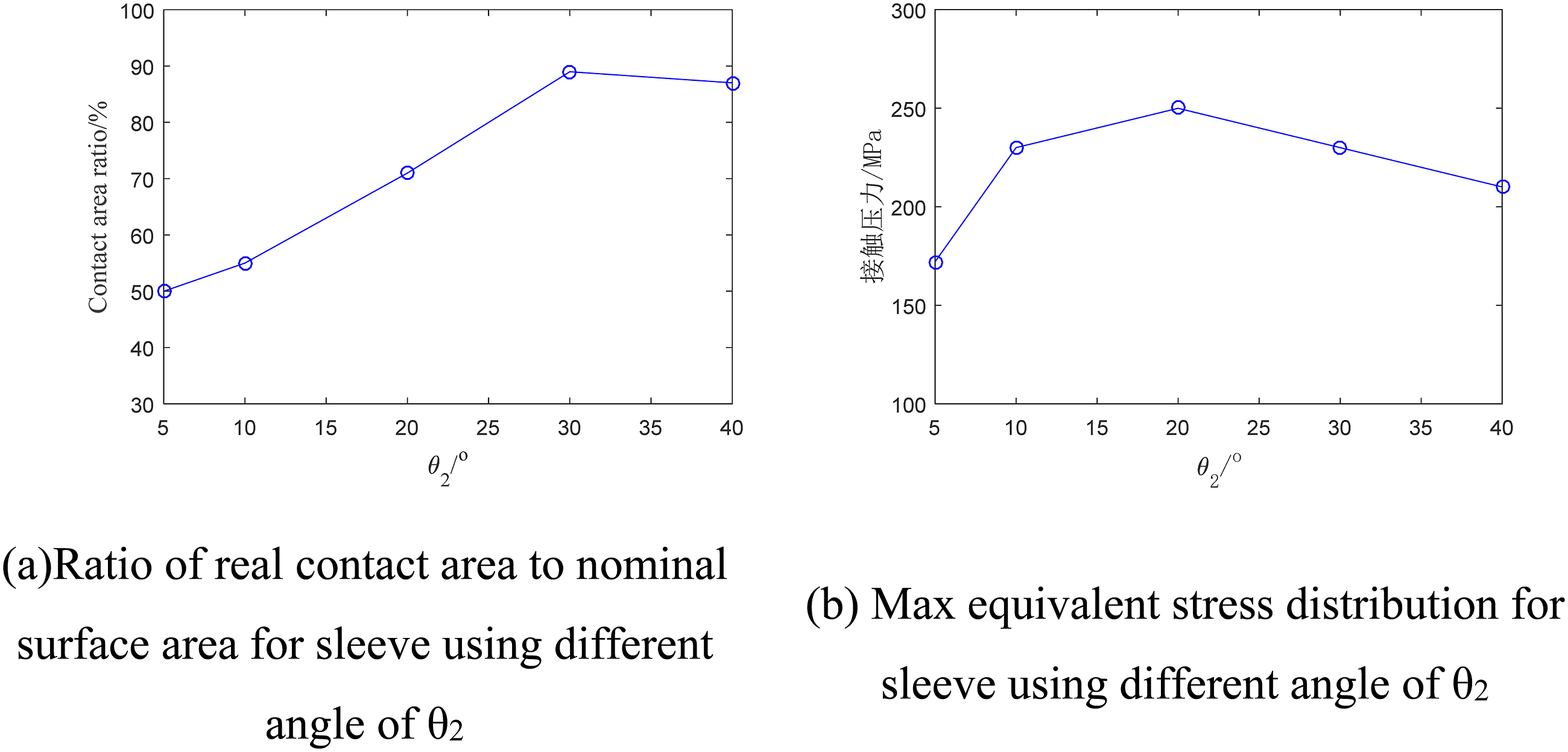
Conclusion
The strength and risk of failure of metal buckled joints in glass fiber-reinforced composite pipes are predicted via the finite element analysis method and combined with the software ANSYS, and the following conclusions can be drawn: (1) According to the finite element analysis, the contribution of the buckling assembly to the composite pipe stress is much greater than the internal pressure effect; that is, the composite pipe stress is mainly induced by the buckling effect. (2) Assuming that the standard state for the metal joints is outside a buckling amount of 5 mm, applying the standard internal pressure of 6.4 MPa, the outer skin and the flat head core pipe experience plastic deformation, the fiber-reinforced layer of the innermost layer of fiberglass tape has a maximum stress of 838 MPa, which is slightly greater than the fiber fracture strength of 800 MPa, the fiber layer of the maximum stress appears in the pipeline and joints near the mouth of the joints, and the sealing performance is good. (3) The structural parameters of the metal joint when the internal pressure is 6.4 MPa are as follows: the optimal buckling amount is 5∼5.5 mm and should be adjusted according to the different internal pressures; the optimal number of serrations is 13; the optimal height of the teeth is 3 mm; and the corrugated serration angle θ1 can be between 50° and 60°. The corrugated serration angle θ2 can be taken between 20° and 30°. This structure can achieve reliable high-pressure sealing, easy installation, strong pull resistance, and strong adaptability in engineering applications, significantly improving the safety and stability of pipe connections. (4) When the internal pressure is 19.2 MPa (3 times the nominal pressure) and the buckling amount is 5 mm, the outer skin of the joint and the core pipe enter the plastic state. The maximum stress in the outer protective layer of the composite pipe reaches 22 MPa, which does not exceed its yield strength, while the maximum stress in the innermost fiber band of the composite pipe reaches 807 MPa, which exceeds the tensile strength of 780 MPa, and the risk of being pulled off is greater.
Footnotes
Author contributions
Minru Yao:Methodology, Investigation, writing - Original Draft. Duo Sun:Methodology, Data curation. Jin Xu:Methodology, Data curation. yuewen Sun:Supervision, project administration and writing - review & editing.Yao Wang:Data curation, Formal analysis. Wanxin Wu:Methodology, Investigation.Hongqiang Wan:Supervision, Validation, Methodology.
Declaration of conflicting interests
The authors declared no potential conflicts of interest with respect to the research, authorship, and/or publication of this article.
Funding
The authors disclosed receipt of the following financial support for the research, authorship, and/or publication of this article: This research is funded by National Natural Science Foundation of China (NSFC) under grant number 52275508, the Xi ’an Science and Technology Bureau, universities and institutes of science and technology personnel service enterprise project under grant number 22GXFW0051 and Xi ’an Science and technology plan under grant number 22NYYF063, Xi ’an Beilin District 2022 science and technology plan under grant number GX2218, General Project grant number 51275374, Youth Science Fund project (51105291) and the Key project of Shaanxi provincial department of education under grant number 2018JS043.
Data Availability Statement
The data used to support the findings of this study are available from the corresponding author upon request.