
Abstract
Thermoplastic composite sandwich structures are widely utilized in aerospace and other high-performance fields due to their advantages of lightweight construction, high strength, high flexural stiffness, excellent damage tolerance, and recyclability. The thermoplastic composite sandwich structure behaves ductilely under static load. However, under impact loading, it may exhibit brittleness or even lead to catastrophic failure. Therefore, in applications where impact considerations are paramount, the design of the sandwich structure must demonstrate good impact properties while also satisfying static and fatigue load requirements. Using a low-velocity drop-weight impact test, this paper investigates the impact response of sandwich structures with various panel configurations and different core thicknesses. Additionally, the influence of damage extent on the vibration characteristics of the sandwich structure under varying impact energies is examined with a vibrometer. The results indicate that the impact peak load of the sandwich structure increases with the panel thickness and core thickness, and the peak load for sandwiches with symmetrical configurations is greater than that for those with unidirectional configurations. The impact energy absorption capability of the sandwich structure is primarily influenced by its failure mode. When both the panel and core are damaged, the structure exhibits superior energy absorption properties. As impact energy increases, the vibration modal frequency of the sandwich structure decreases, while the damping ratio increases.
Keywords
Introduction
The sandwich structure is usually composed of two layers of panels and a lightweight core material in the middle. The panel is usually composed of high-strength and high-modulus materials such as metal and fiber-reinforced resin matrix composites, and the core material is generally composed of porous or lightweight materials such as foam and honeycomb. Ferri et al. 1 compared the damage resistance and energy absorption properties of graphite/bismaleimide composite laminates and sandwich plates through drop-weight impact and static indentation tests. It was found that sandwich plates absorb more energy than laminates and have less deflection when absorbing the same maximum energy. Among many different core materials, honeycomb core material is more common in the aerospace industry. Honeycomb sandwich structure is widely used in automotive, aerospace, and transportation engineering design because of its high specific energy absorption, high stiffness, and strength-to-weight ratio.2–7 Because honeycomb core material is a porous solid material, it will not damage the stiffness and energy absorption characteristics of the structure while reducing the total weight of the structure. 8 At the same time, compared with many other rigid foams, honeycomb can be better controlled in terms of mechanical properties because of its customizable porous thin-walled structure. 9
Among different types of honeycomb core materials, Nomex honeycomb and aluminum honeycomb are widely used because of their low cost and low density. However, these two types of honeycombs are greatly affected by humidity factors, which will lead to a significant decrease in the mechanical properties of the structure, thereby reducing its service life. 10 At present, many studies have focused on the sandwich structure of thermosetting composites, such as epoxy resin, because of its excellent mechanical and thermal properties, which are widely used in the matrix system of Fiber Reinforced Polymer (FRP) composites. However, the out-of-plane properties of thermosetting composites are relatively poor, especially under impact load. In addition, once the thermosetting composites are cured, they can neither be molded nor recycled.11,12 Compared with thermosetting composites, thermoplastic composites have many advantages, including excellent impact resistance, post-formability, high chemical resistance, good shock absorption, and recyclability.11,13
The dynamic impact response of the honeycomb sandwich structure is greatly affected by honeycomb size parameters and honeycomb materials. Cao et al. 14 studied the impact mechanical properties of sandwich structures with cross-grid cores, and compared the energy absorption of the structure under different impact velocities. Foo et al. 15 found that the low-velocity impact resistance of aluminum sandwich panels can be improved by higher aluminum foil density, larger aluminum foil thickness, or smaller unit size. Gunes and Arslan proved by numerical simulation that the stiffness and stability of the aluminum honeycomb sandwich structure increase with the decrease of the core size, but the core thickness has little effect on the impact response. 16 Crupi et al. 17 used 3D computed tomography to study the failure mode and damage of aluminum honeycomb sandwich panels under impact loading. It is found that the honeycomb collapse area with a smaller unit size is more concentrated. To improve the crashworthiness of the honeycomb sandwich structure, many scholars choose different kinds of composite materials with different specific strengths as the panel of the sandwich structure. Crupi et al. 18 used glass fiber reinforced polymer (GFRP) panels to improve the energy absorption and bearing capacity of honeycomb sandwich structures. Liu et al. 19 studied the impact response of Nomex honeycomb sandwich structure and fiber reinforced woven fabric composite panel under different impact energy, impactor mass, and tilt angle. Wu et al. 20 and He et al. 21 compared the impact response of carbon fiber reinforced polymer (CFRP) sandwich panels with honeycomb cores of different parameters by experimental and numerical methods, respectively. Zhang et al. 22 studied the drop-weight impact response of a Nomex honeycomb sandwich structure with a CFRP panel. The energy absorption mechanism of the sandwich structure is related to the failure mode of the structure. Various failure modes that may occur during the low-velocity impact of the sandwich structure include local indentation/cracking of the panel, buckling of the core material, debonding between the panel and the core material, extrusion failure of the lower panel, and full penetration of the sandwich structure.14,23–26
Structural components in aerospace are subjected to various dynamic loads, and these dynamic loads can also produce excessive vibration. Therefore, it is necessary to understand the main response modes of the structure. Vibration is described as the time-dependent motion of particles around their equilibrium state. The dissipation of vibration energy with time and distance in solid media and structures is called damping. Damping occurs in places with friction, reduces motion, and disperses energy. The loss factor or ratio between the energy dissipated in each cycle and the energy still present in the system is called the damping capacity of each material. 27 The sandwich structure is usually composed of a high-strength panel and a lightweight core material. Compared with the mean structure, the sandwich structure has excellent density specificity, high bending stiffness and strength, as well as high impact resistance and vibration resistance.28,29 Sheikhi et al.27,30,31 studied the vibration behavior of sandwich structures and prepared sandwich structures composed of aramid fiber fabric reinforced polymer (AFRP ), carbon fiber reinforced polymer (CFRP ), glass fiber reinforced polymer (GFRP) panels, and aluminum panels with a fixed cork core. The impact vibration reduction and vibration test of the panels were carried out respectively. It was found that the panels based on CFRP showed the highest damping and stiffness characteristics. The shear thickening fluid (STF) and multifunctional shear thickening fluid (M-STF) with different rheological properties were added to the sandwich structure composed of GFRP and cork core, and the sandwich structure composed of polyvinyl chloride (PVC) and aluminum panel, respectively. The final research results show that the addition of intelligent materials such as STF and M-STF can greatly improve the vibration resistance of the structure.
Vaidya et al. 32 studied the vibration response of composite sandwich plates composed of laminated plates and aluminum foam under free boundary conditions. Hao et al. 33 studied the bending-torsion coupling of functionally graded sandwich plates. Liu et al. 34 studied the nonlinear vibration of a functionally graded shell with porosity on an elastic substrate. Duc et al. 35 studied the dynamic response and impact of a composite honeycomb sandwich plate, and analyzed the influence of geometric characteristics on the natural frequency. Zhang et al. 36 studied the influence of elastic parameters and gradient classification on the natural frequency of functionally graded honeycomb sandwich panels, and studied the dynamic response of functionally graded honeycomb sandwich panels under low-velocity impact.
Although numerous studies have been conducted on the low-velocity impact behavior of sandwich structures, the impact response and post-impact vibration characteristics of thermoplastic composite honeycomb sandwich structures such as GF/PP composites have not been thoroughly investigated. Sandwich structures are widely used in load-bearing and functional applications due to their high strength, lightweight nature, and integrated functionalities. Thermoplastic composites like GF/PP exhibit excellent toughness, impact resistance, high damage tolerance, short molding cycles, and recyclability. GF/PP sandwich structures combine the advantages of both components: the high strength and stiffness of GF/PP face sheets and the toughness of PP core materials, forming a “rigid-flexible” hybrid structure. While sandwich structures typically demonstrate ductile behavior under static loads, they often exhibit brittleness under dynamic loads such as impact. Therefore, improving their impact resistance is critical for applications involving dynamic loading. This study employs low-velocity drop-weight impact tests to analyze the mechanical response and energy absorption of sandwich structures with different face sheet layup configurations and core thicknesses, revealing the influence of these parameters on impact performance. Since varying impact energies induce different damage modes that alter vibration characteristics (natural frequency, damping ratio, and modal shapes), vibration tests are conducted to evaluate the effects of impact-induced damage on dynamic behavior. A correlation is established among three key aspects: the impact performance of structural parameters, post-impact damage modes, and their influence on vibration characteristics. The results provide foundational data for optimizing the design of GF/PP sandwich structures in dynamic load applications.
The GF/PP sandwich structures in this study were fabricated using the non-isothermal molding process of high-temperature mold forming low-temperature workpiece proposed by Guo et al. 37 This method prevents excessive melting of the core material, thereby avoiding thickness reduction and mechanical property degradation that could lead to structural collapse. Furthermore, the process achieves bonding between face sheets and core solely through PP resin melting without introducing additional materials, eliminating potential interfacial factors that might compromise impact performance.
Test methods and test materials
Test Materials and Test Equipment
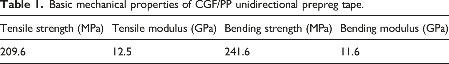
Basic mechanical properties of CGF/PP unidirectional prepreg tape.
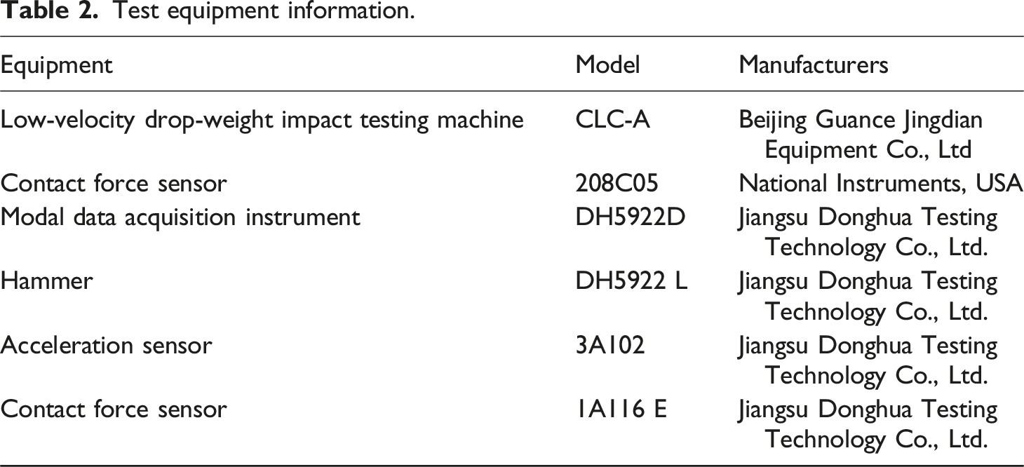
Test equipment information.
Sample Preparation
Preparation of GF/PP thermoplastic composite sandwich structure by non-isothermal molding process of high-temperature mold forming low-temperature workpiece is shown in Figure 1.
38
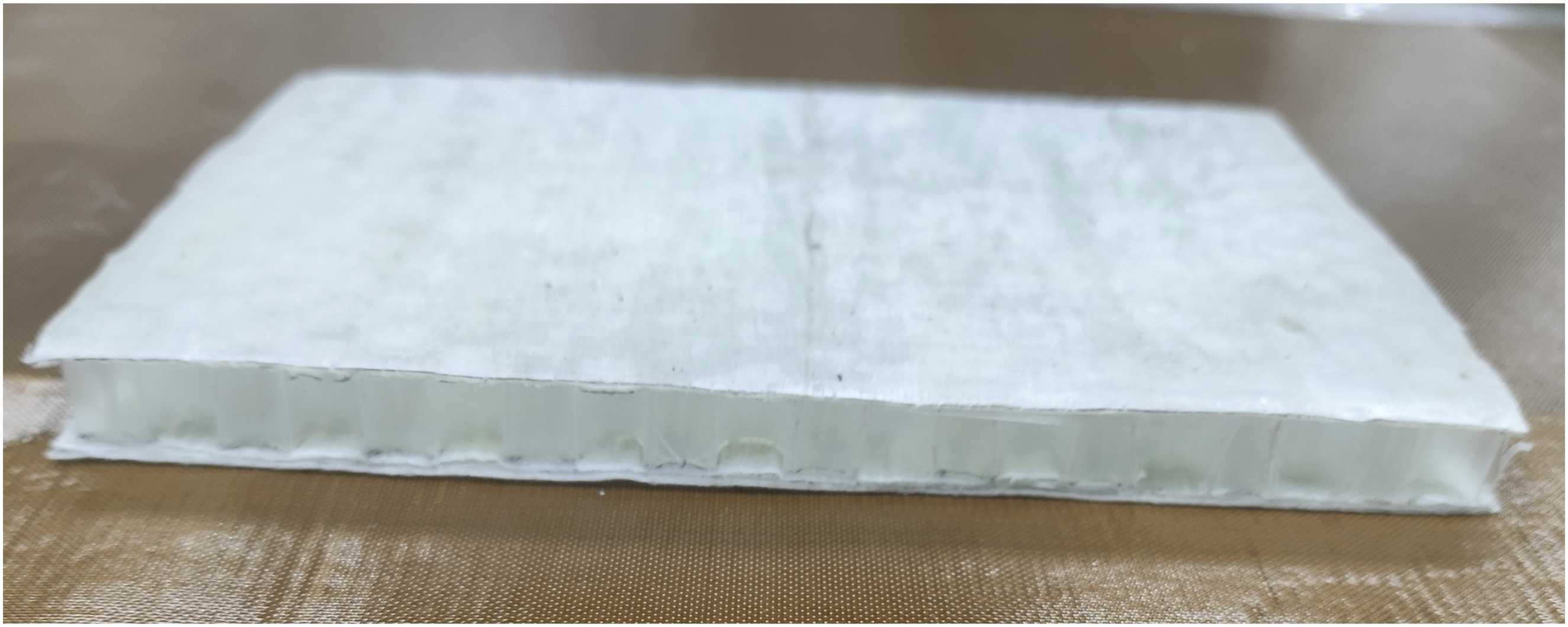
The length of the sample is 150 mm, and the width is 100 mm. To facilitate the analysis, each sample uses a feature label. H indicates the thickness of the core material of the sandwich structure. For example, H10-0/90/0 indicates that the thickness of the core material is 10 mm, the panel is 3 layers of GF/PP prepreg, and the configuration is 0/90/0. Figure 2 is the impact specimen of the GF/PP sandwich structure prepared in this paper. Sandwich structures with different core thickness, different panel thickness, and different configurations were prepared, respectively, and then impact tests were carried out. High temperature mold forming low temperature workpiece non-isothermal molding process to prepare sandwich structure diagram.
38
. GF/PP impact specimens.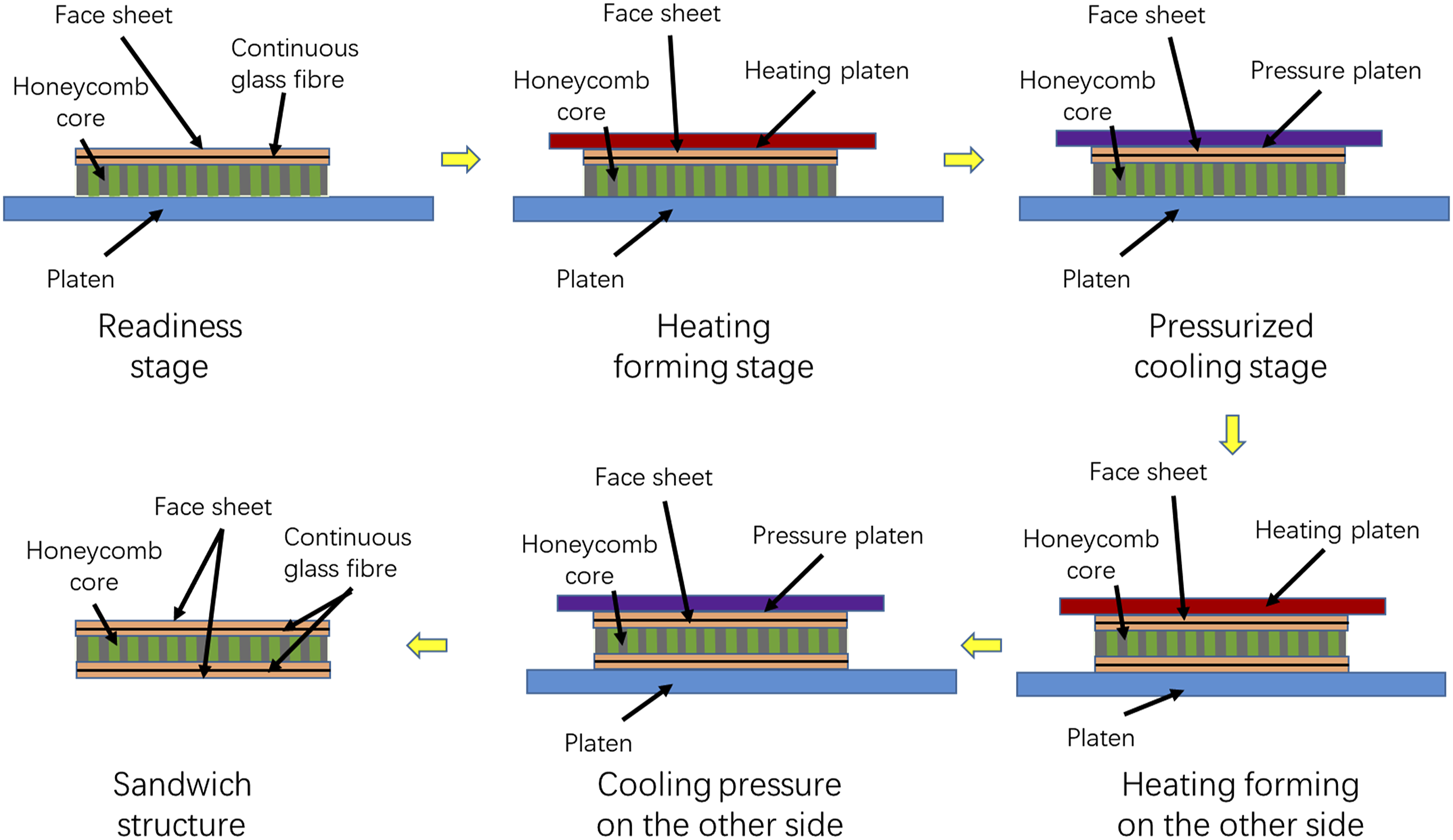
Low-velocity Drop-Weight impact Test
The low-velocity drop-weight impact test machine was used to carry out the low-velocity impact test on the prepared samples. The test method was referred to as ASTM D7136/7136M《Standard Test Method for Measuring the Damage Resistance of a Fiber-Reinforced Polymer Matrix Composite to a Drop-Weight Impact Event》.
39
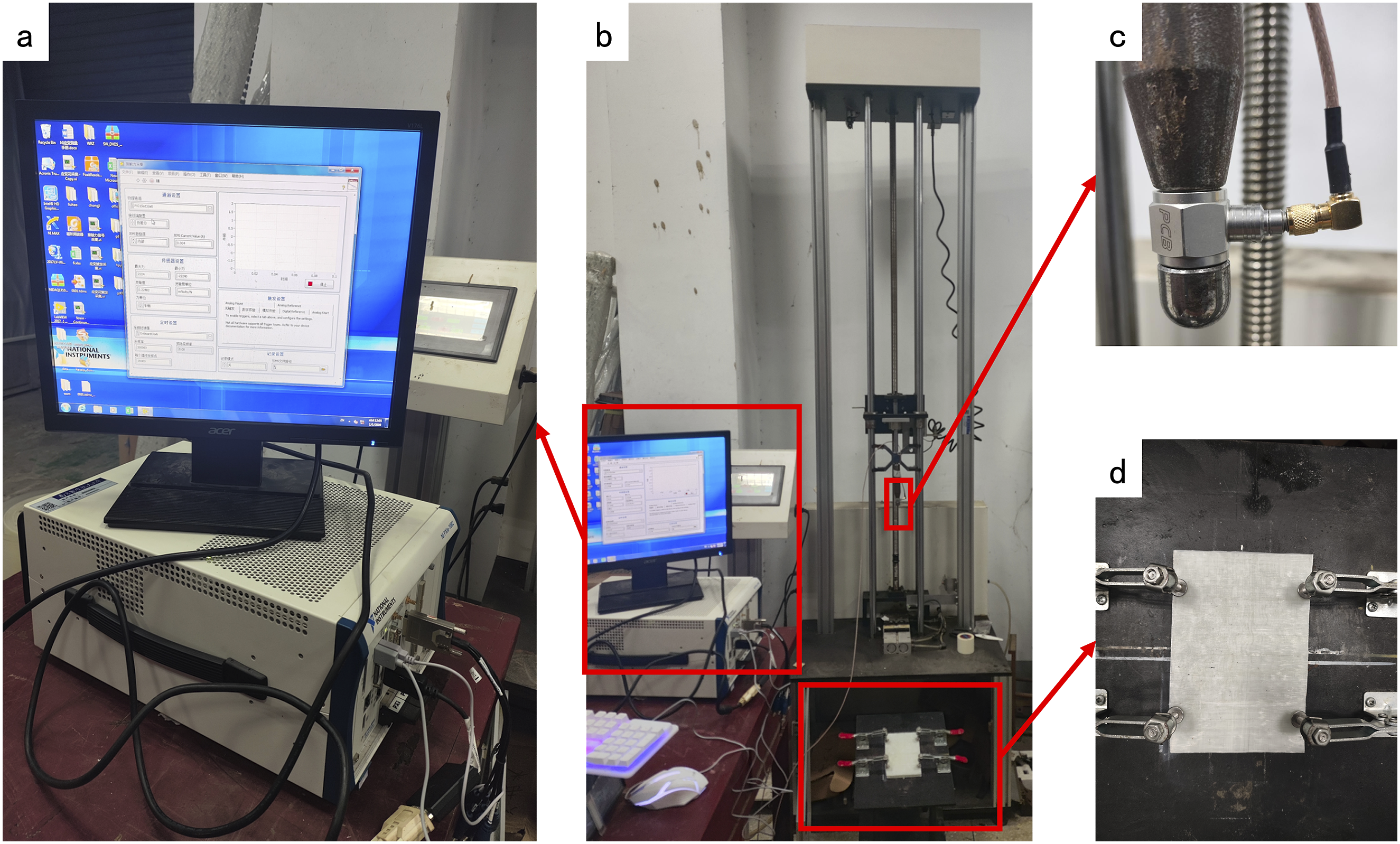
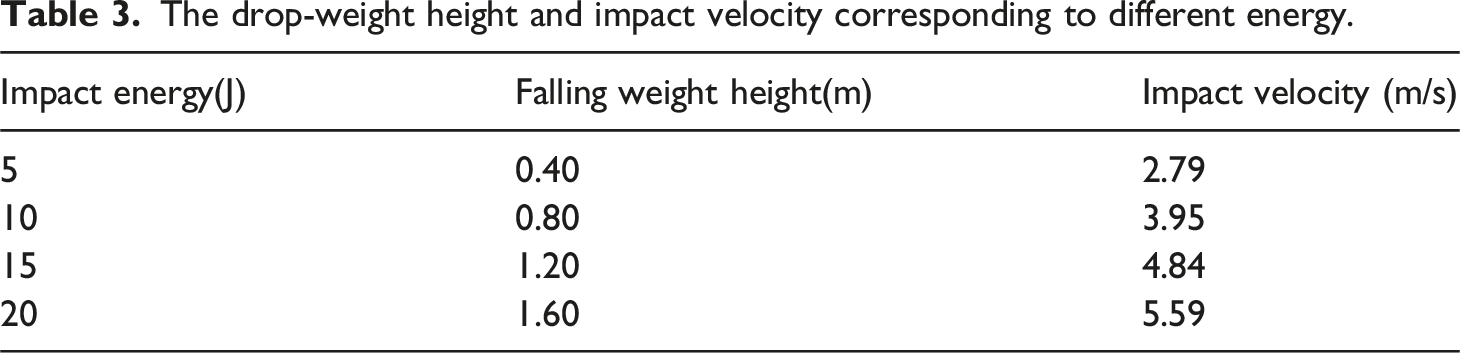
The low-velocity drop-weight impact test device used in this paper is shown in Figure 3. The test device consists of four parts: the double-column impactor guide device, the impactor and the force sensor, the impact load acquisition device, and the sample clamping device. There is a pneumatic valve on the upper part of the clamping device, which is automatically closed after the impact to prevent the drop-weight from re-impacting the test sample due to rebound. The total mass of the drop-weight is 1.28 kg. The impactor is a steel hemispherical impactor with a diameter of 16 mm. The specimen is clamped on four sides. The impact energy is adjusted by adjusting the distance between the drop-weight and the upper surface of the specimen. The formula (1) is the calculation formula of impact energy, which can be calculated according to the formula. Table 3 shows the drop-weight height and impact velocity corresponding to different energies. Drop-weight low-velocity impact test device (a) Drop-weight impact load acquisition device (b) Drop-weight impact overall device (c) impactor and sensor (d) Sample clamping device. The drop-weight height and impact velocity corresponding to different energy.
When the impactor connects to the sensor and contacts the sample, the load acquisition device displays the load during the impact process. The sampling frequency is 200 KHz, and 200,000 data points are collected per second. Finally, a continuous curve is output, and the load-time curve during the impact process is processed.
In the test, the load-time curve during the impact process is obtained by the sensor, and the velocity-time curve during the impact process can be obtained by integrating it.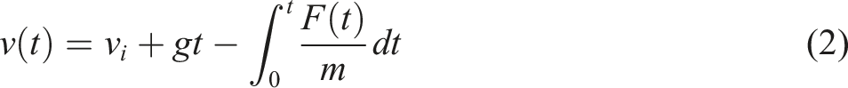
According to the velocity-time curve, the displacement-time curve can be calculated :
Finally, the energy-time curve of the sample absorbed during the impact process is obtained :
Finally, through step-by-step calculation, the load-time curve output by the load acquisition device is transformed into an energy-time curve.
The specific energy absorption of the structure is calculated according to the ratio of the total energy absorption to the mass of the structure :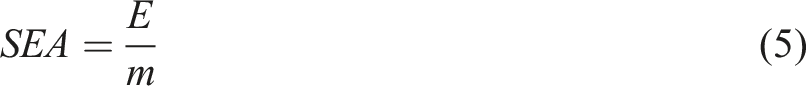
Modal Test of Force Method
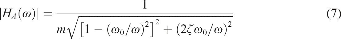
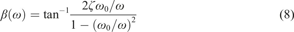
Modal analysis is a common method in structural dynamics, which mainly includes experimental modal analysis and computational modal analysis. The modal test in this paper is to excite and respond to the test piece, and obtain the modal parameters of the structure through the identification and analysis of the vibration signal. Modal parameters include modal frequency, modal damping ratio, and modal shape, which are the natural vibration characteristics of the structure. Each mode has a fixed frequency, damping ratio, and vibration shape. Among them, the main research method of modal analysis is the frequency response function. By decoupling the matrix equation that expresses the vibration characteristics of the system, the modal parameters of each order are obtained, which provides a basis for studying the vibration characteristics of the structure. The acceleration frequency response function of the damped system can be expressed in the form of a complex exponent :
In the process of structural system vibration, damping has the effect of dissipating energy, and its essence is to convert the dissipated energy into heat energy or other energy.
40
The free vibration attenuation method is a classical method for measuring damping in the time domain. When the system vibrates freely under the initial displacement, the amplitude will decay exponentially with time under the action of damping, and the damping ratio can be measured by calculating the corresponding amplitude. The expression of the free vibration of a single-degree-of-freedom damped system is :
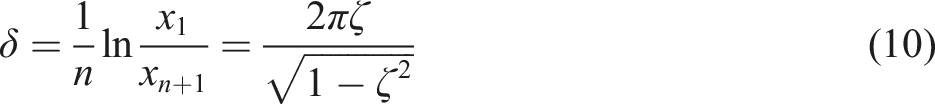
Figure 4 is the test device diagram of the modal test in this paper. The test device is mainly composed of a data acquisition system, signal collection software, a hammer with a contact force sensor, and an acceleration sensor. The signal collection software can collect the signal of the change of contact force and acceleration during the hammer striking. Modal test device diagram.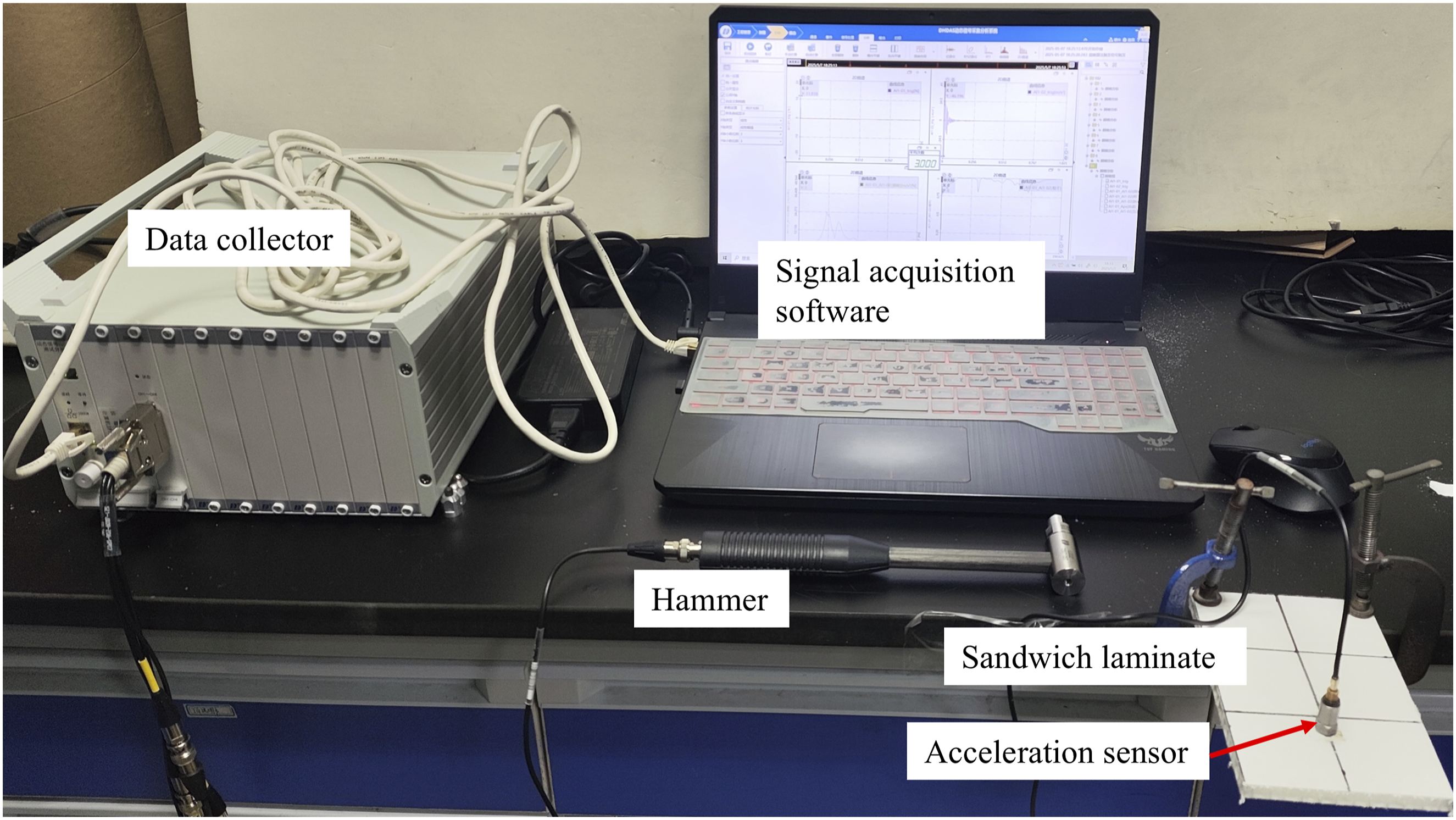
To effectively establish the relationship between damage severity and modal vibration characteristics of sandwich structures under varying impact energies while eliminating the influence of extraneous factors such as specimen dimensions and boundary conditions, this study maintained identical specimen dimensions (150 mm × 100 mm) for both vibration modal testing and impact testing. The sandwich structures were subjected to four distinct impact energy levels (5J, 10J, 15J, and 20J). Subsequent vibration characterization was performed to compare the dynamic responses between pristine (non-impacted) specimens and post-impact specimens across these energy levels. This controlled experimental approach ensures direct correlation analysis between impact-induced damage progression and corresponding modal parameter variations.
Figure 5 is the point diagram of the modal test. In this paper, the cantilever support method is used to fix the sandwich structure, and an approximate simulation of the free boundary condition is presented. The sandwich plate is fixed on the table surface by using the C-type clamp, and the acceleration sensor is fixed at the cantilever end, that is, the measuring point position 5, because the nodes near the support end are fixed, which is a plane constraint, so the measuring point is not set, as shown in Figure 5(a). The force hammer with a contact force sensor is used to hit the point of the sandwich structure point by point, and the acceleration signal at point 5 is obtained. The average value of each point is hit three times. The frequency response function is obtained by the dynamic signal test and analysis software. The PolyLSCF method is used to calculate the steady state of the collected data, and the modal frequency, modal damping ratio, and modal shape of the sandwich structure are obtained. Schematic diagram of modal test point (a ) Modal model in software ( b ) Modal model in test.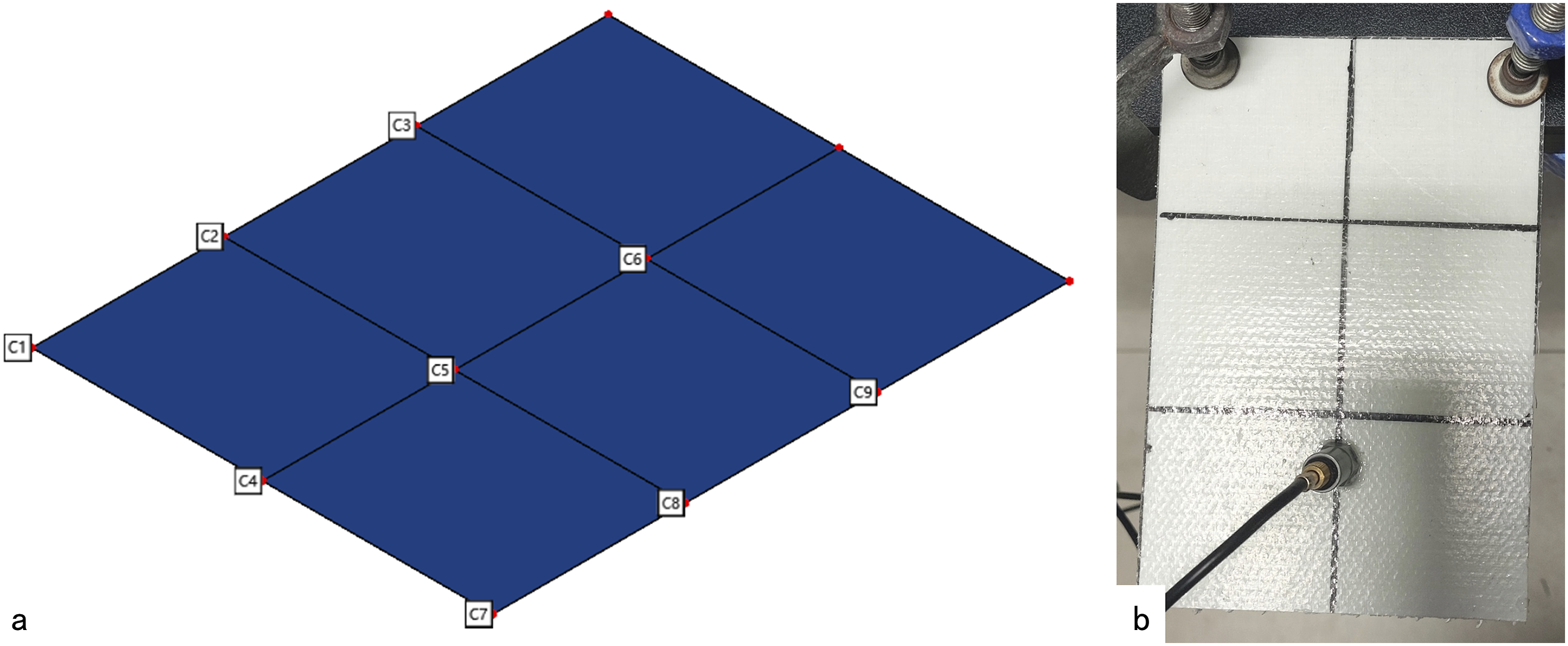
Results and discussion
Analysis of load-time curve of sandwich structure
Low-velocity impact response of sandwich structures with different configurations
In order to study the influence of the configurations of the sandwich structure panel on the overall bearing impact load of the structure, three kinds of panels with different thicknesses were prepared, respectively, and the thickness of the panel was changed by changing the number of layers of the GF/PP prepreg. The 0° unidirectional ply and the 0°、90° symmetrical ply were prepared for each panel thickness, and the sandwich structure impact samples were prepared with a core material of 10 mm thickness.
The impact peak load of sandwich structures with different panel configurations.
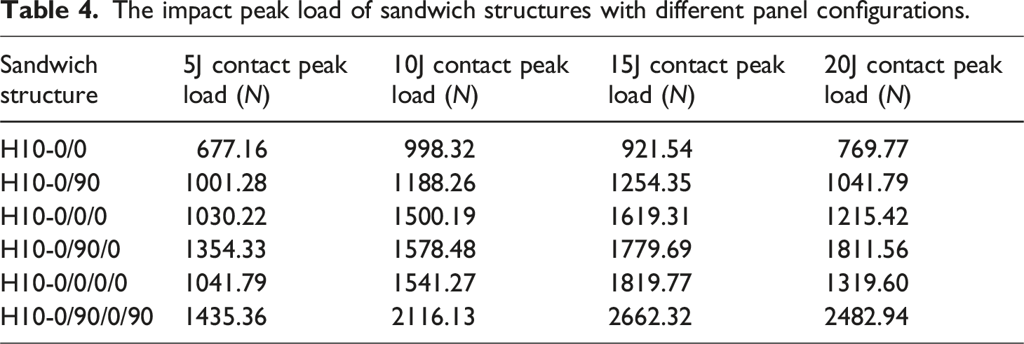
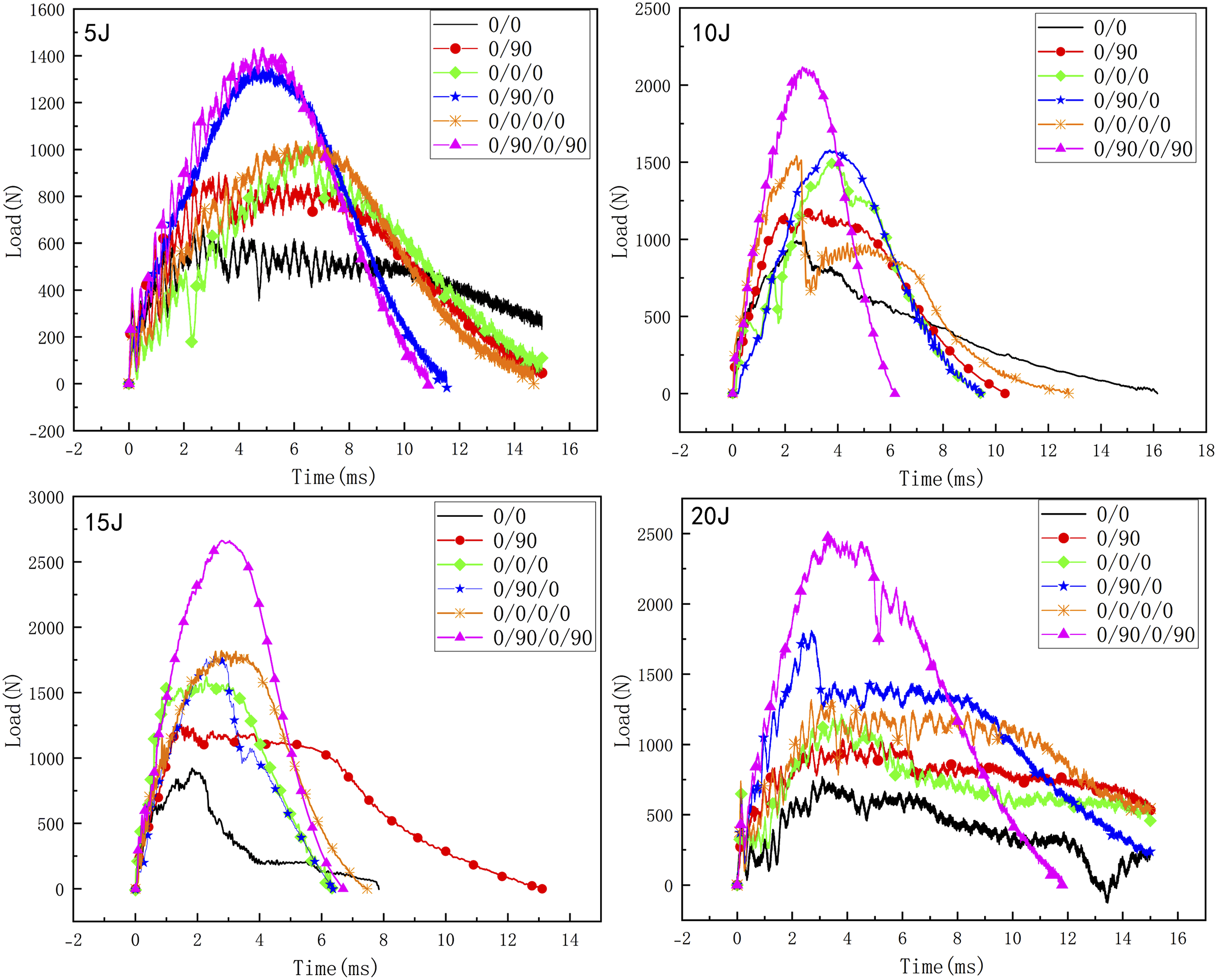
Impact load-time curves of different panel configurations.
Figure 7 shows the post-impact photos of sandwich structures with different panel configurations under 15J impact energy. According to the photos, when the impact energy is 15J, the sandwich structure of 0/0 panel has serious damage, and the core material and upper and lower panels of the structure are completely destroyed, indicating that the sandwich structure of 0/0 panel cannot withstand the impact energy of 15J, and has completely failed below the impact energy of 15J. Therefore, the peak contact load of the structure under 15J impact energy will be lower than the peak load of 10J impact energy. The sandwich structure with 0/90 face sheet layup exhibited micro-cracks around the indenter position and debonding damage at the structural edges. The 0/0 and 0/90 layup configurations induced distinct failure modes: The 0/0 layup aligned fibers unidirectionally, creating pronounced anisotropy. While demonstrating high strength and stiffness along the fiber direction, this configuration exhibited weak transverse properties, resulting in stress distribution heavily dependent on fiber orientation. Post-impact photographs revealed that damage primarily manifested as face sheet cracks. Notably, the 0/0 layup configuration displayed lower peak impact loads compared to the 0/90 configuration. For the 0/0/0 layup, cracks developed in both vertical and horizontal directions at the impact zone. In contrast, the 0/0/0/0 layup showed only fiber-aligned cracks. The 0/90/0 and 0/90/0/90 layups exhibited impact-induced denting with peripheral cracks, though the dent area in the 0/90/0 configuration significantly exceeded that of the 0/90/0/90 configuration. Increasing face sheet thickness through additional plies enhances structural stiffness, thereby improving impact resistance, reducing damage severity, and increasing peak load capacity. For 0° unidirectional layups, impact loads transfer predominantly along the fiber direction, generating localized stress concentrations near the impact site. This promotes penetrating cracks parallel or perpendicular to fiber orientation. Conversely, 0/90 symmetric layups distribute impact energy through cross-ply fiber networks, delaying localized damage. Consequently, such configurations develop finer web-like or radial crack patterns rather than catastrophic failures. Sandwich structure samples with different panel configurations after 15J energy impact.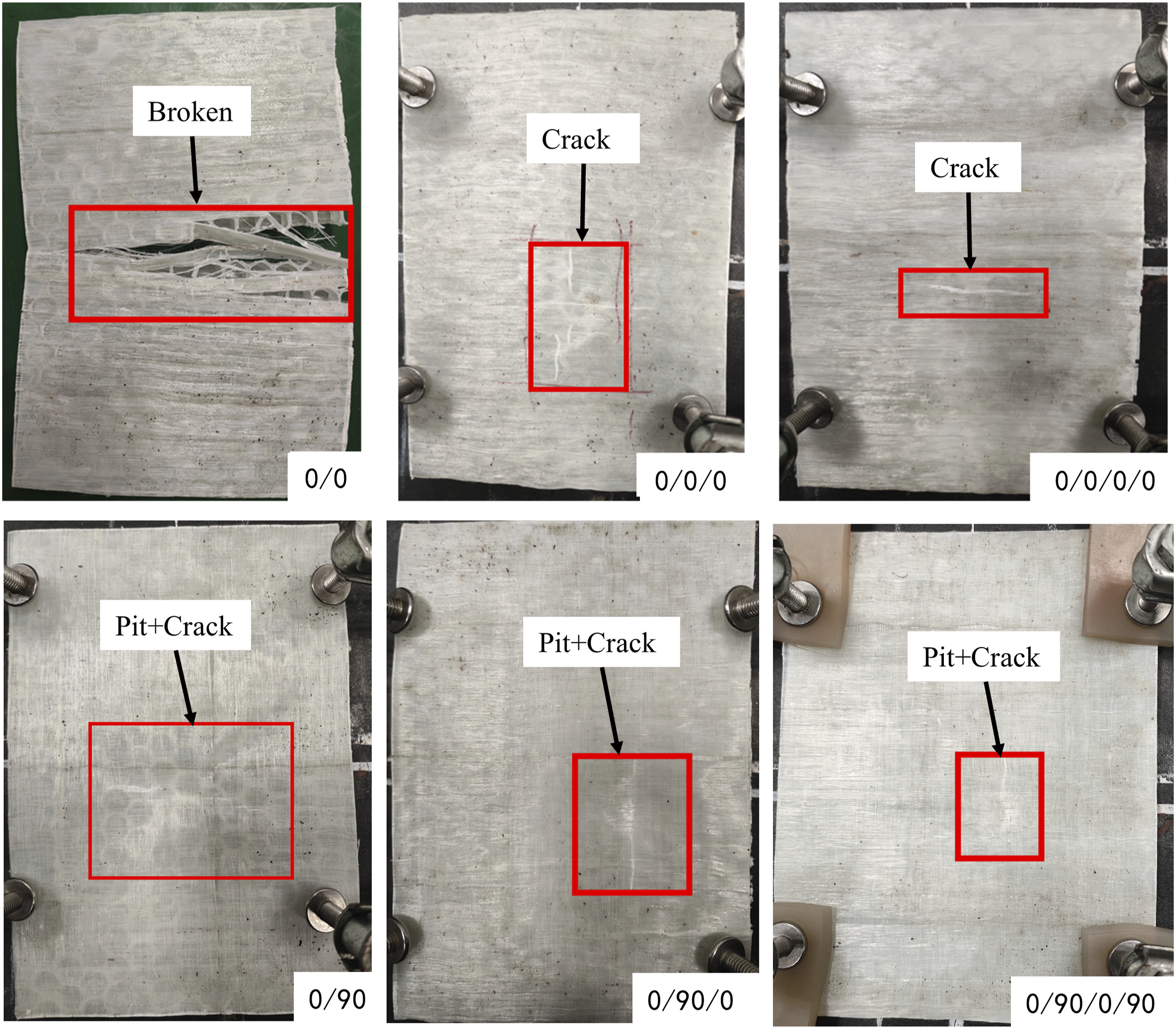
Low-velocity impact response of sandwich structures with different core thickness
This section studies the low-velocity impact responses of sandwich structures with different core thicknesses under different impact energies. The panel uses three layers of GF/PP prepreg, all using a 0/90/0 configurations. The thickness of the core material of the sandwich structure is 5 mm, 10 mm, 15 mm, and 30 mm.
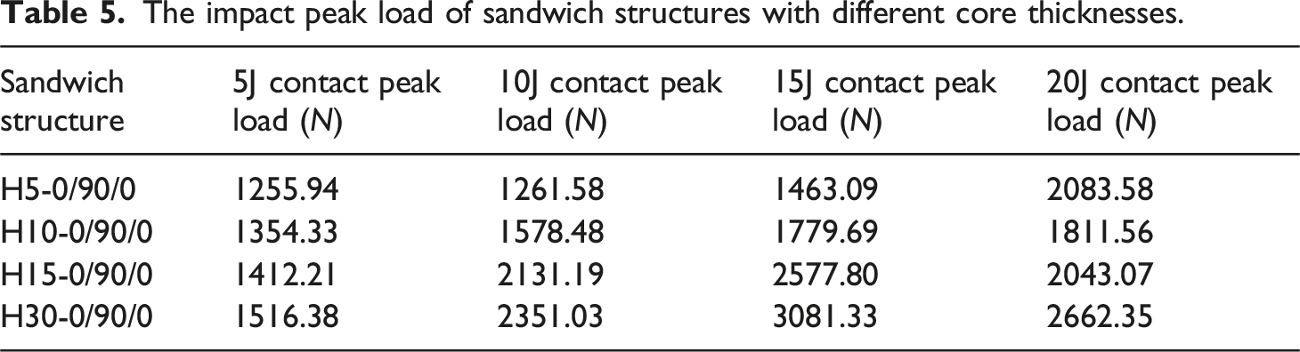
The impact peak load of sandwich structures with different core thicknesses.
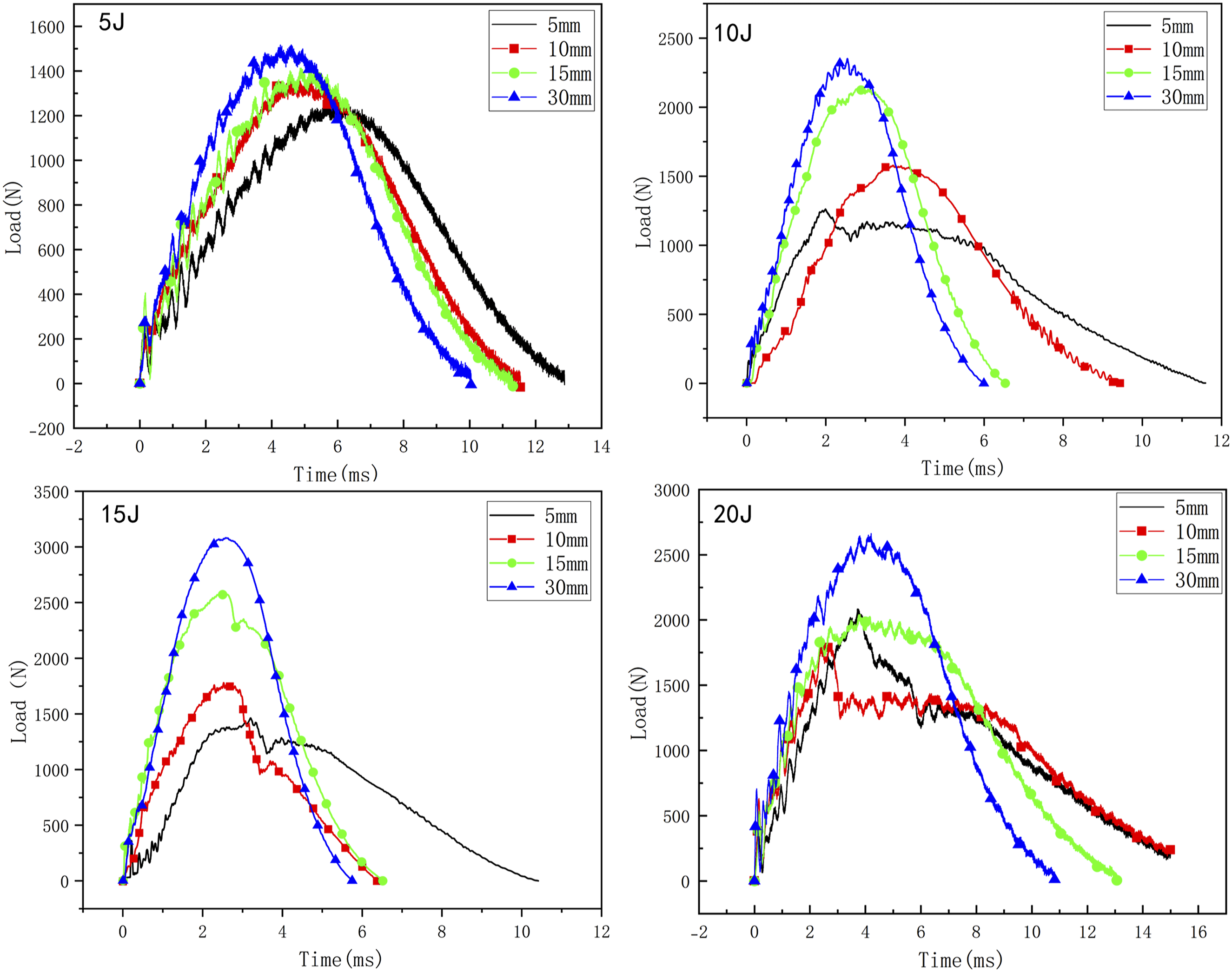
Impact load-time curves of different core material thicknesses.
At 5J impact energy, all four core thickness configurations exhibit similar load-time curve profiles resembling sinusoidal patterns with pronounced oscillatory behavior. For the 5 mm core thickness configuration under impact energies exceeding 10J, the load-time curve maintains a prolonged plateau phase after peak load attainment rather than immediate decline, followed by gradual load reduction accompanied by significant structural damage. At 20J impact energy, both 10 mm and 15 mm core thickness configurations demonstrate load plateau formation before slow decay, indicating plastic deformation failure. These observations reveal that thinner-core sandwich structures fail earlier with increasing impact energy due to their panel-dominated stiffness characteristics. The reduced global bending stiffness in thin-core configurations promotes large deformations under equivalent impact energies, where localized plastic deformation becomes the primary failure mechanism. This initiates progressive damage propagation through the outward expansion of plastic zones. Conversely, thicker-core configurations demonstrate substantially enhanced global stiffness, enabling predominant elastic bending deformation under impact. The elevated structural stiffness effectively suppresses localized deformation by converting impact energy into global bending moments, allowing energy dissipation through elastic stress redistribution before reaching material yield limits. However, when impact energy exceeds structural capacity, core shear fracture failure occurs, manifested by characteristic load plateau phases followed by gradual load reduction in the load-time curves.
Figure 9 shows the peak load comparison histogram of the sandwich structure prepared in this paper under different impact energies. It can be seen that under the same impact energy, the impact peak load of the sandwich structure will increase with the increase of core thickness and panel thickness. Under the same impact energy, the same panel thickness and core thickness, the peak load of the sandwich structure with 0° and 90° alternating ply is higher than that of the 0° unidirectional ply. The peak load of different sandwich structures under different impact energies. Note : A is H10-0/0, B is H10-0/90, C is H10-0/0/0, D is H10-0/90/0, E is H10-0/0/0/0, F is H10-0/90/0/90, G is H5-0/90/0, H is H10-0/90/0, I is H15-0/90/0, J is H30-0/90/0.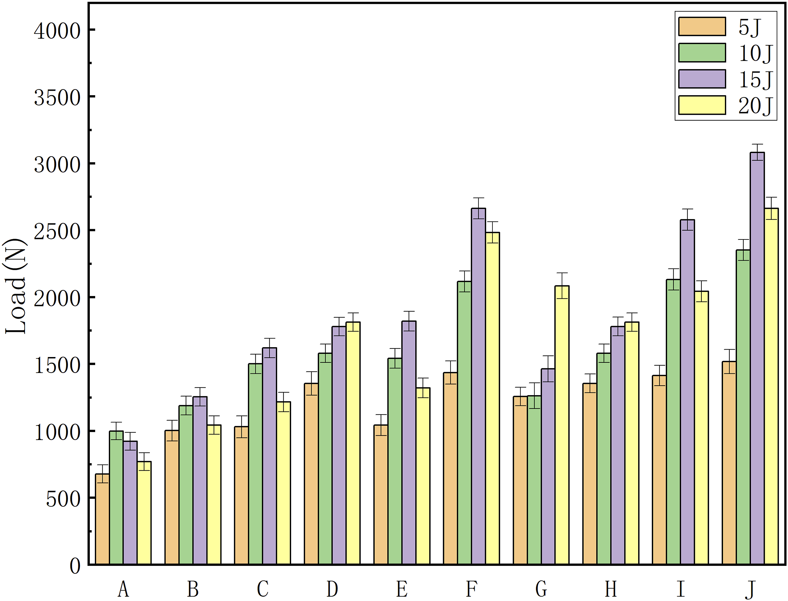
Energy Absorption Properties Analysis of the sandwich Structure
Energy absorption properties of sandwich structures with different panel configurations
The energy absorption-time curve is mainly divided into two stages. The first stage is the downward movement of the impactor, and the impact energy is gradually transformed into the internal energy of the sandwich structure, corresponding to the rapid rise stage of the energy absorption-time curve. The second stage is the process of impactor rebound. The elastic potential energy stored in the sandwich structure is converted into the kinetic energy of the impactor, and the impactor rebounds upward, corresponding to the gentle decline stage of the energy absorption-time curve. In the early stage of impact, the sandwich structure sample absorbs energy through deformation under a small impact load, so the slope of the curve is low. With the continuous downward movement of the impactor, the contact area of the impactor increases, so that the impact load increases rapidly, the deformation displacement of the sandwich structure will increase, and even the sandwich structure will exhibit damage behavior, so the slope of the energy absorption-time curve will be relatively high. Finally, because the impact load decreases, the impact displacement reaches the maximum value, the energy absorption-time curve gradually stabilizes, and the slope of the curve decreases to 0.
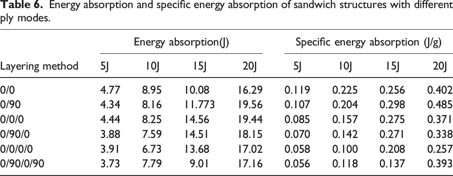
Energy absorption and specific energy absorption of sandwich structures with different ply modes.
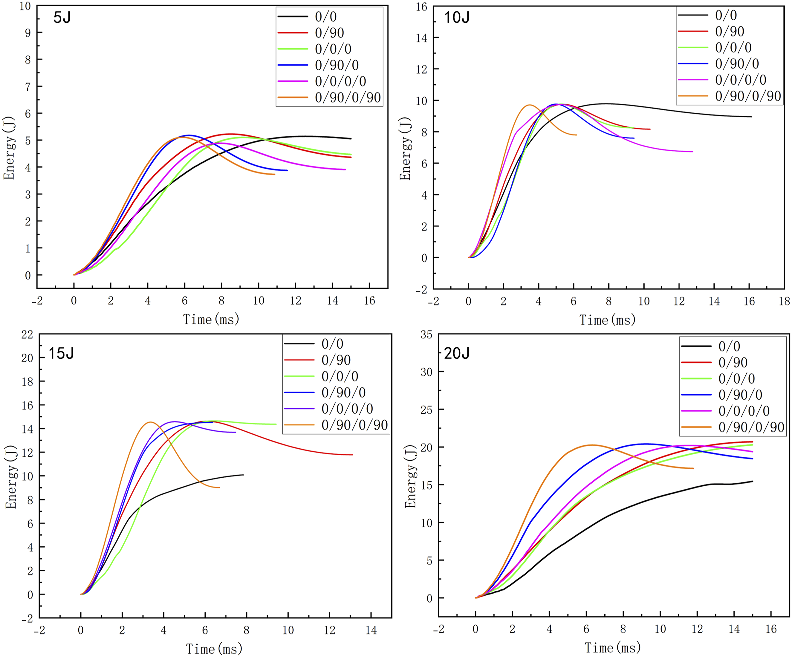
Energy absorption-time curves of sandwich structures with different panel configurations.
As shown in Figure 7, sandwich structures with 0° unidirectional face sheet layups primarily exhibit large penetrating cracks in the panels, oriented both parallel and perpendicular to the fiber direction. This failure mechanism involves fiber breakage and longitudinal tearing of prepreg materials during impact. Progressive crack propagation under loading creates continuous damage paths through synergistic interactions between transverse fiber fracture and longitudinal prepreg delamination, resulting in enhanced energy absorption performance. In contrast, the 0/90/0/90 layup configuration demonstrates reduced energy absorption. Post-impact analysis reveals localized denting at the impact zone with peripheral microcracks. The high-stiffness cross-ply layup effectively constrains panel deformation and damage propagation, redirecting impact forces to the core material. Consequently, the core experiences predominantly brittle compressive failure rather than plastic deformation, failing to establish effective energy dissipation pathways. While 0/90 symmetric layups mitigate bending-tension coupling effects and reduce stress concentration to delay delamination growth, excessive symmetry concentrates impact energy in localized regions. This phenomenon restricts global energy absorption capacity and reduces energy absorption efficiency by limiting the development of distributed damage mechanisms.
According to Tables 6, it can be seen that within the impact range that the sandwich structure can withstand, as the thickness of the sandwich structure panel increases, the energy absorption of the sandwich structure will decrease. Because when the panel thickness of the sandwich structure increases, the overall stiffness of the structure will also increase, and the structure’s ability to resist deformation will be stronger. At the same time, the increase in the thickness of the panel makes it more difficult for the impactor to penetrate the panel of the structure, so that the core of the structure is squeezed to withstand the impact load. Although the increase in panel thickness will increase the impact peak load of the structure, the thin-walled structure of the honeycomb core material does not undergo a densification stage, which will reduce the energy absorption capacity of the structure. The panel thickness of the sandwich structure increases, and the mass of the structure will also increase, so the specific energy absorption of the sandwich structure will also decrease with the increase in the thickness of the structural panel.
Energy absorption properties of sandwich structures with different core thickness
Energy absorption and specific energy absorption of sandwich structures with different core thickness.
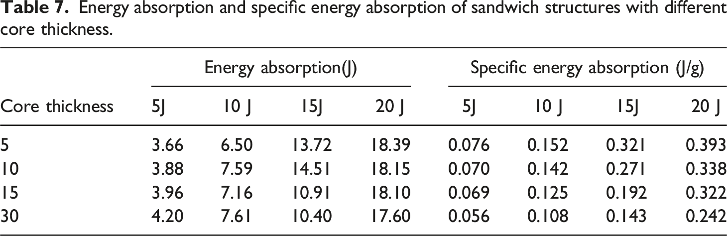
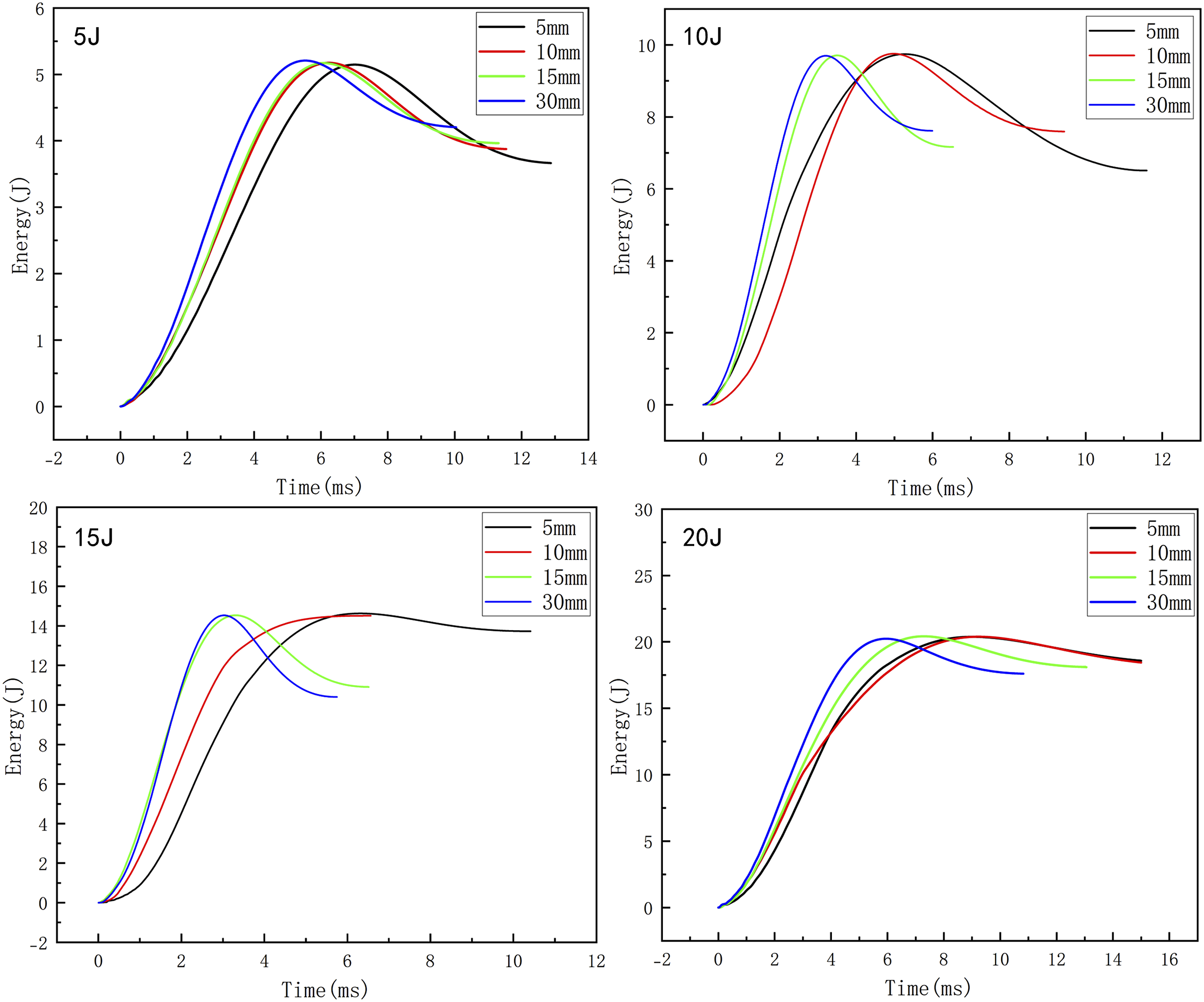
Energy absorption-time curves of sandwich structures with different core thicknesses.
Figure 12 shows the energy absorption and specific energy absorption of the sandwich structure under different impact energies. Combined with the previous analysis, it can be found that the influence of panel thickness, core thickness, and panel configurations on the energy absorption and specific energy absorption of the structure is not monotonous. The thick panel can resist the direct penetration of the impactor, so that more energy can be absorbed through the compression and shear of the core material and the bending deformation of the panel. However, when the panel is too thick, the impact energy will be rebounded by the elastic deformation of the panel; that is, the elastic deformation of the structure occurs during the impact, and the impact energy is converted into the kinetic energy of the rebound of the punch. The core material cannot participate in the crushing energy absorption, so the energy absorption of the structure is reduced. When the thickness of the sandwich structure increases, the compressible volume increases, and more energy is absorbed through plastic deformation, buckling, or crushing. At the same time, the thicker core material can delay the local buckling of the panel, allow greater overall bending deformation, and improve energy absorption efficiency. However, if the core material is too thick, the stiffness of the sandwich structure will be significantly improved, which will lead to the change of the failure mode of the structure during the impact process, which will lead to the local buckling of the structure or the delamination of the interface, rather than the progressive crushing, resulting in the reduction of the energy absorption capacity of the structure. When the layup of the structure is completely composed of 0° unidirectional layup, the structure has high axial stiffness and strength, but it is prone to brittle fracture of the fiber, and the energy absorption is reduced. The 0/90 symmetrical ply can reduce the bending-tensile coupling effect caused by impact, reduce the local stress concentration, delay the delamination expansion, and improve the energy absorption capacity of the structure through multi-mode damage synergistic energy absorption. However, excessive symmetry will lead to the impact energy concentrated in the local area, so that the energy absorption efficiency is limited. The energy absorption and specific energy absorption histogram of the sandwich structure under different impact energies (a) Energy absorption ( b ) Specific energy absorption.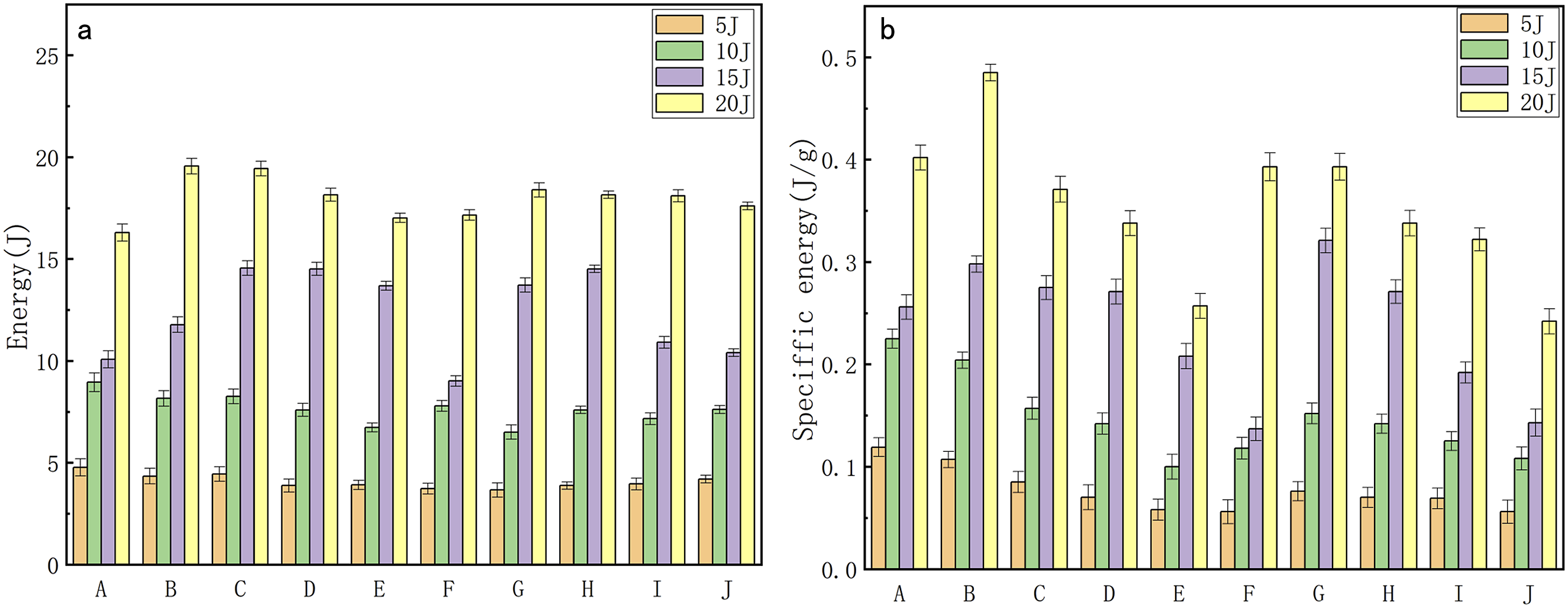
The study reveals that the energy absorption of sandwich structures during impact does not exhibit a monotonic relationship with variations in peak impact load. The peak impact load is predominantly governed by the structure’s local stiffness. Enhancing the thickness of both face sheets and core materials, along with optimizing the face sheet layup configurations, effectively increases the peak impact load of sandwich structures. Energy absorption capacity is primarily determined by the failure mechanisms: structures experiencing severe damage progression with diversified failure modes demonstrate superior energy absorption through coordinated damage evolution during impact events.
Effect of impact on vibration Characteristics of sandwich Structure
The GF / PP sandwich plate is impacted with different impact energies, and the picture of the sandwich plate after impact is shown in Figure 13. It can be seen from the figure that as the impact energy increases, the area and depth of the pits in the sandwich structure will also increase. There are cracks near the pits of the panel. The larger the impact energy is, the more obvious the cracks of the sandwich structure panel are. The pit generated by the impact of the impactor is approximated as a circle, and the diameter and depth of the pit are measured. The diameter and depth of the pit produced by the sandwich structure under different impact energies are shown in Table 8. Sandwich structure after different impact energies. Pit size and mode of sandwich plate under different impact energies.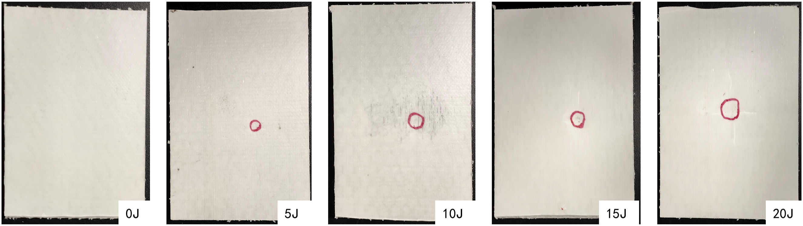
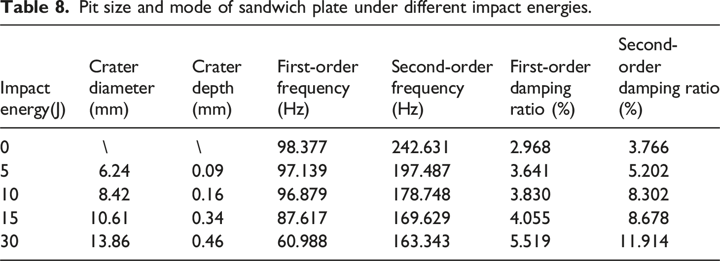
Figure 14 presents C-scan damage images of sandwich structures after impacts at different energy levels. Impact-induced pits appear as blue regions in the C-scan images. At 5J impact energy, a near-circular blue zone is observed without significant peripheral damage. Under 10J impact energy, narrow, elongated, irregular features emerge around the pit periphery, indicating microcrack formation adjacent to the primary damage zone. When the impact energy increases to 15J, both the blue area and associated cracks exhibit substantial expansion in size and penetration depth. At 20J impact energy, dramatic increases in pit dimensions and crack propagation are evident, with deep, extensive cracks radiating from the impact site, confirming severe structural degradation. These observations demonstrate that increasing impact energy not only amplifies pit dimensions (area and depth) but also accelerates crack propagation, thereby exacerbating structural damage severity. C-scan images of the sandwich structure under different impact energies.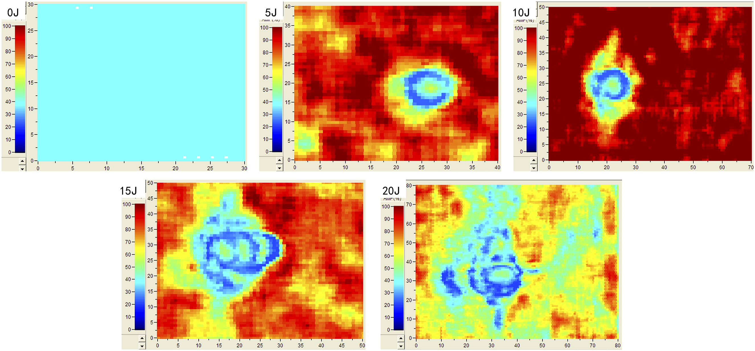
The vibration test of the sandwich plate with different impact energies is carried out by the force method. Table 8 lists the modal frequency and damping ratio of the sandwich plate with different impact energies. According to the table, it can be seen that the natural frequency of the sandwich plate decreases with the increase of the impact energy. Because the increase of the impact energy leads to the internal damage of the structure, the structural panel has pits, and the core material will also be compressed, thus weakening the overall stiffness of the structure. The natural frequency is positively correlated with the stiffness, and a decrease in stiffness directly causes a decrease in structural frequency. The higher-order modes are more sensitive to the change of local stiffness, and the local damage caused by the impact further weakens the local stiffness of the structure. Therefore, with the increase of impact energy, the second-order mode of the structure decreases more than the first-order mode. The damping ratio of the structure increases with the increase of the impact energy, because the internal damage of the structure caused by the impact (crack propagation of the panel, compression deformation of the core material, etc.) and its synergistic effect increase the energy dissipation path of the structure. Because the vibration modes involved in the higher-order modes are more complex, the local damage after the impact of the sandwich structure will aggravate the local energy dissipation, so the increase of the second-order damping ratio of the structure is more significant.
The impact damage of the sandwich structure affects the local stiffness of the structure and then affects the natural frequency of the structure. Combined with Figures 13 and 14, it can be seen that under the impact energy of 5J, the panel of the structure has local small cracks, which will reduce the local stiffness and lead to a decrease in the modal frequency of the structure. The friction between the cracks will increase the path of energy dissipation, and the structural damping ratio will increase. When the impact energy is 10J, the structure has obvious pits, the damage area is larger, and more serious cracks appear around the pits. The cracks and pits of the panel will lead to a decrease in the interface inertia moment of the structural panel, and the modal frequency will continue to decrease. As the degree of damage increases, the structural damping ratio continues to increase. Under the impact energy of 15J, the pit depth and area of the structure are larger, and the core material also receives obvious extrusion deformation. The interlayer results show delamination damage, which destroys the continuity of the structure. At the same time, the stratification produces viscous dissipation, and the damping ratio of the structure will also increase. At the impact energy of 20J, in addition to the large area of pits in the impact position, there are also penetrating cracks around the pits, and the core material is seriously compressed or even crushed. Therefore, the large-scale stratification of the structure and the crushing of the core material will greatly reduce the equivalent stiffness of the structure and reduce the modal frequency. However, due to the serious damage, the energy dissipation path increases, and the structural damping ratio will increase.
In the low-velocity impact test of this paper, the impact energy is relatively small, and the impactor will not penetrate the sandwich structure, but there will be pits in the sandwich structure. As the impact energy increases, the diameter and depth of the pits will increase accordingly. At the same time, the local stiffness of the structure decreases, but the whole structure remains intact, resulting in a small decrease in the modal frequency of the structure. At this time, the energy dissipation mode of the structure is mainly viscoelastic deformation and interface friction, so the damping ratio of the structure will increase.
Figure 15 is the modal shape diagram of the sandwich plate under different impact energies. The basic vibration modes of the sandwich plate with different impact energies are basically the same. The first-order modal shape corresponds to the bending deformation of the structure, and the second-order modal shape corresponds to the torsion deformation of the structure. According to the schematic diagram of the modal shape, it can be seen that when the sandwich plate is fixed by the cantilever support method, the displacement of the cantilever end of the first-order modal shape of the structure is the largest, and the two-point displacement of the cantilever end of the second-order modal shape is the largest. Modal shape diagram of sandwich plate with different impact energies.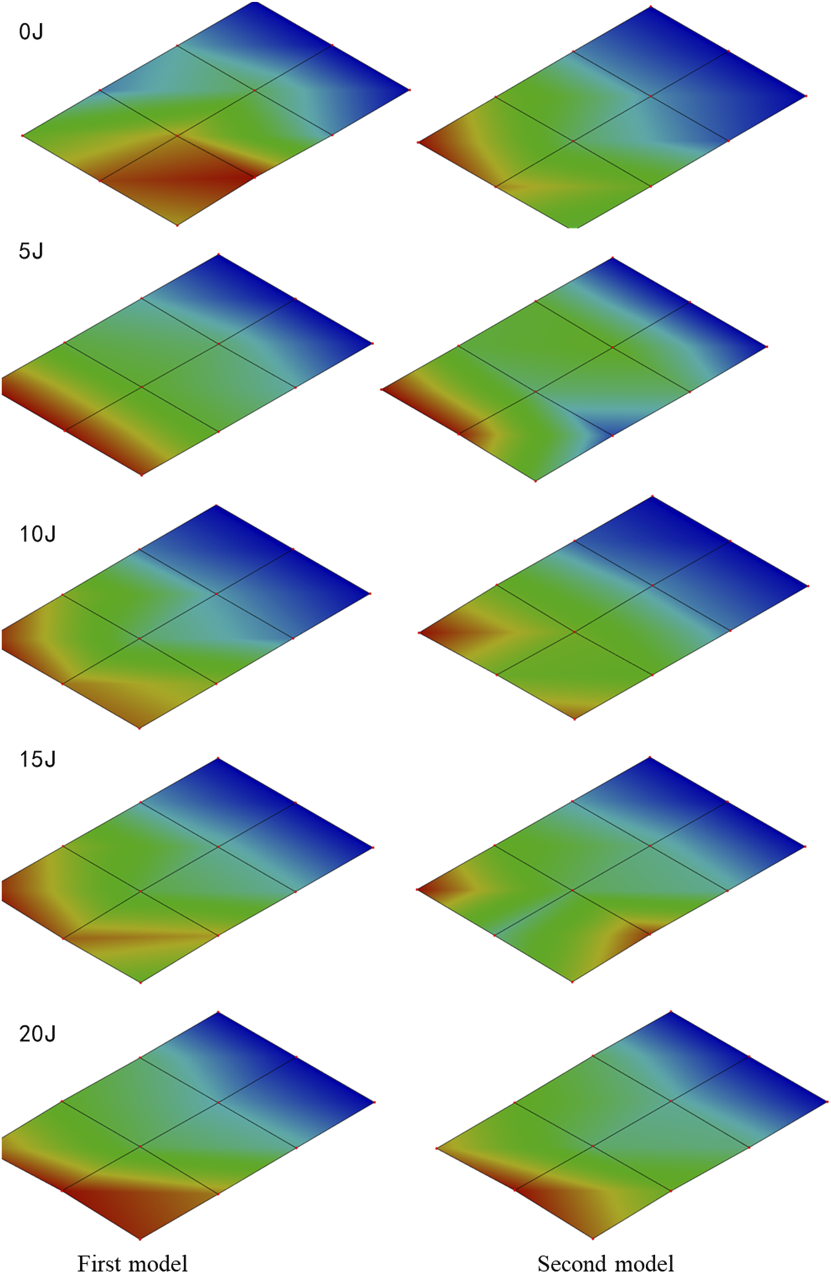
Comparing the modal shapes of sandwich plates with different impact energies, it is found that the modal shapes of sandwich plates are less sensitive to impact damage, and there is no obvious difference. This is because the damage caused by different impact energies to the sandwich structure is mostly local non-penetrating damage, and the damage location generally occurs in the high-stress area in the center of the sample. A small range of damage is equivalent to uniform stiffness attenuation in the overall vibration, rather than introducing new vibration mode nodes or anti-nodes. In addition, the boundary conditions of the cantilever support suppress the disturbance of the local damage to the overall modal shape of the structure through geometric constraints. The displacement of the fixed end of the sandwich structure approaches 0, and the first-order bending modal energy is mainly concentrated at the free end. The damage area is generally located at the center of the structure, so the contribution of damage to modal strain energy is limited, resulting in a small change in the overall vibration mode of the structure.
According to the analysis of the influence of different impact energies on the vibration characteristics of the sandwich structure, it is found that when the structure is impacted at a lower energy, the failure mode of the structure is mainly the micro-cracks of the panel. At this time, the stiffness of the structure is slightly reduced, and the damping ratio will be slightly increased. When the impact energy is high, the damage to the structure extends to the core material of the structure. In addition to the damage to the panel, it is also accompanied by the compression collapse of the core material of the structure. The synergistic effect of various damages further reduces the stiffness, and the damping ratio of the structure will increase nonlinearly. When the impact energy of the sandwich structure increases, the stiffness degradation and energy dissipation capacity of the structure increase, which shows that the vibration frequency of the structure decreases and the damping increases, reflecting the progressive damage process of the structure from matrix damage to delamination failure.
Conclusion
In this paper, the low-velocity drop-weight impact test of the GF/PP sandwich structure is carried out. By analyzing the contact load response and energy absorption properties of the structure during the impact process of different impact energies, the influence of the configurations of the sandwich structure panel and the thickness of the core material on the impact properties of the structure is studied, and the damage degree of the structure is analyzed. Combined with the vibration modal analysis, the effect of damage modes on the vibration characteristics of the sandwich structure after impact is studied. (1) Under the same impact energy, the impact peak load of the sandwich structure will increase with the increase of core thickness and panel thickness. Under the same impact energy, the same panel thickness, and core material thickness, the peak load of the sandwich structure with symmetrical panel configurations will be higher than that of the sandwich structure with unidirectional configurations. (2) The energy absorption of the sandwich structure mainly depends on the failure mode of the structure, and the energy absorption will not change monotonously with the change of the thickness of the core material or the configurations of the panel. When pits appear on the panel after impact, the core material is crushed and densified, and the whole structure undergoes plastic deformation and progressive damage failure. The structure absorbs energy through multiple damage modes. At this time, the sandwich structure has good energy absorption properties. (3) The influence of impact on the vibration characteristics of the sandwich structure depends on the damage mechanism of the sandwich structure in the process of impact. In the process of low-velocity impact, with the increase of impact energy, the local stiffness of the sandwich structure will decrease, so the modal frequency of the sandwich structure will decrease slightly, the damping ratio will increase, and the modal shape will be less sensitive to impact damage.
Footnotes
CRediT authorship contribution statement
Declaration of conflicting interests
The author(s) declared no potential conflicts of interest with respect to the research, authorship, and/or publication of this article.
Funding
The author(s) disclosed receipt of the following financial support for the research, authorship, and/or publication of this article: Our work is supported by the funding of “Special Funds of 2023 Jiangsu Provincial Science and Technology Plan”, and the funding number is ZAG23009.
Data Availability Statement
All data generated or analyzed during this study are included in this published article.