
Abstract
The study presents a comprehensive analysis of the high-temperature pyrolysis process of CFRP, along with a comparative analysis between single-step and two-step methods during thermal recycling. Before thermal recycling through a customized muffle furnace, optimized pyrolysis process parameters were determined using thermogravimetric analysis (TGA), optical microscopy, scanning electron microscopy (SEM), and EDS to evaluate degradation characteristics and surface morphology of reclaimed carbon fibers (CFs). The results show near 100% recyclability of CFs through a single-step and two-step in 1.25 h and 2 h, respectively, achieving more than 81% tensile strength and 83% modulus. The optimized parameters in the single-step process are heating CFRP waste at 25°C/min till 490°C under an air atmosphere. CFRP is first pyrolyzed under argon and nitrogen atmospheres at 650°C separately, followed by oxidation under air atmosphere until 490°C using a two-step method. Analysis of surface morphology shows a slight improvement in the quality of reclaimed CFs with two-step E1 than that of two-step E2 and single-step E3. During thermal recycling, the influence of isothermal time on CFRP under air atmosphere is highly significant. The findings emphasize the critical impact of heating ranges, temperature limits, and atmosphere, providing insights into the thermal recycling process to reclaim CFs for remanufacturing advanced composite materials.
Keywords
Introduction
Carbon fiber-reinforced polymer (CFRP) composites are widely used in various aerospace, automobile, maritime, construction, sports, and household industries due to their high thermal resistance, mechanical strength, stiffness, low toxicity, and low weight. 1 The growing usage of CFRP has led to enormous waste, including scraps from the manufacturing process, end-of-life (EoL), and damaged components. It highlights the significance of recycling CFRP waste for environmental and economic benefits.
The global CFRP market, valued at over USD 8.6 billion by 2020, is anticipated to triple by 2030, 2 and waste disposal will increase accordingly. The global waste of CFRP composite has reached 62 kilotons by 2020, 3 and this output is assumed to rise to approximately 483 kilotons by 2030. 4 The manufacturing costs of carbon fiber precursors consume 50% of CFRP production costs, and equipment consumes one-third, 5 which is nearly 83% of the total CFRP production cost to produce only carbon fibers.6,7 The manufacturing process of CFRP components produces almost 40 percent of CFRP waste. 8 For instance, the CFRP makes up about half of the body of the Airbus A350 and Boeing 787 Dreamliner aircraft, 9 and the construction process of the Boeing 787 aircraft’s main wings only produces nearly 1000 tons of CFRP waste annually. 10 Consequently, it is required to respond to the waste recycling issues of CFRP. The CFRP waste comes from two primary sources: the components made from CFRP that are damaged or reached EoL, and virgin prepregs or CFRP composite scraps that are not required in manufacturing.
Figure 1 demonstrates the source of CFRP waste: the products or components reach expiration or are damaged, and scraps from the production process are leftover composites, hybrid yarns, and nonwovens from the dry-laid or wet-laid process.
11
The first category is divided into large and small-to-medium CFRP waste. The primary sources of large CFRP waste are large pieces of equipment such as rockets, satellites, missiles, wind turbine blades, space shuttles, and ships. These pieces of waste equipment exhibit good mechanical properties after they are scrapped. On the other hand, small-and-medium-sized CFRP waste is generated from automobile bodies, interior parts, sports equipment, household scraps, etc. These scraps are generated from damage to automobile bodies caused by collisions, high-degree heat exposure that causes material deformation, and leftover after EoL. Recent studies have addressed the CFRP recycling issue by adopting chemical,
2
thermal,12,13 and mechanical recycling
14
along with repair and recovery mechanisms of CFRPs.
15
CFRP waste generation sources and types.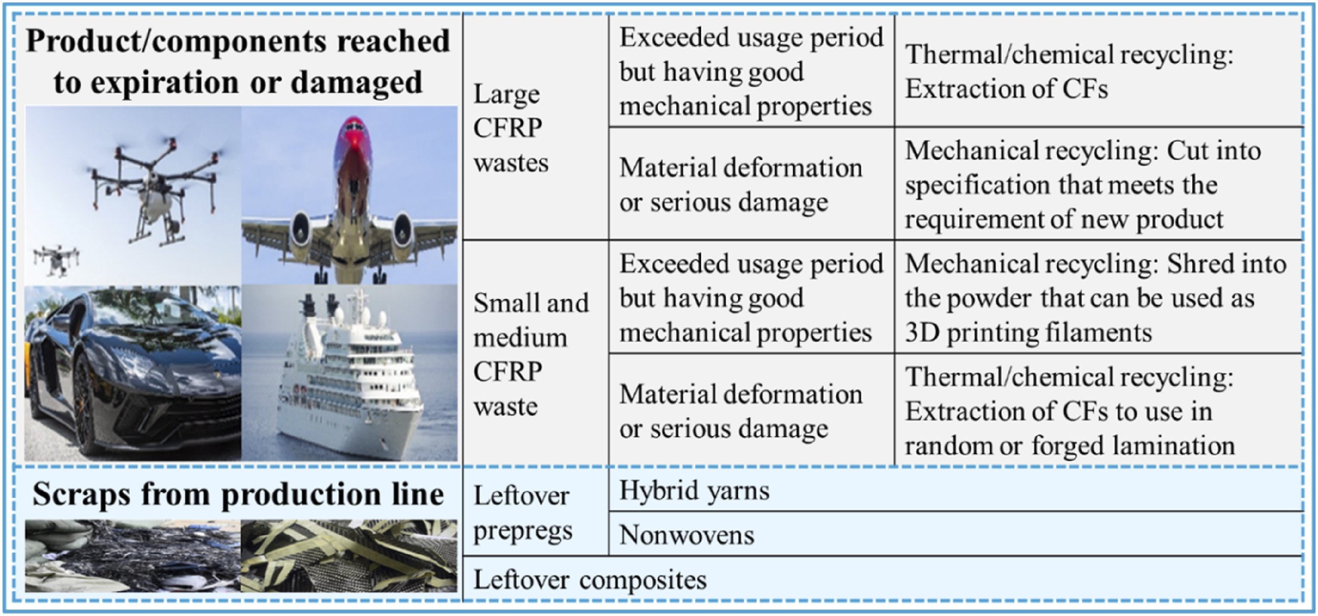
Figure 2 categorizes the prominent waste recycling methods. Thermal recycling is an effective and environmentally friendly method that includes high-temperature pyrolysis, microwave pyrolysis, and fluidized bed recycling methods.16–18 In contrast, chemical recycling breaks down the thermoset matrix and includes dissolution repolymerization, electrochemical, and solvolysis to recover non-defective carbon fibers. However, this method is less recommended as it requires costly chemicals to decompose the epoxy matrix, such as tetralin, sulfuric acid, nitric acid, and super/subcritical alcohols and water.19,20 In addition, mechanical recycling involves shredding material into smaller pieces, followed by ball milling or fluidized bed reactor grinding. However, carbon fibers are typically reclaimed as powder or randomly sized fragments from CFRP and the fibers’ mechanical strength deteriorates, and the surface is damaged during the crushing or grinding. Although this approach is cost-effective, the recycling proportion and quality of recyclates are comparatively less. CFRP waste recycling methods.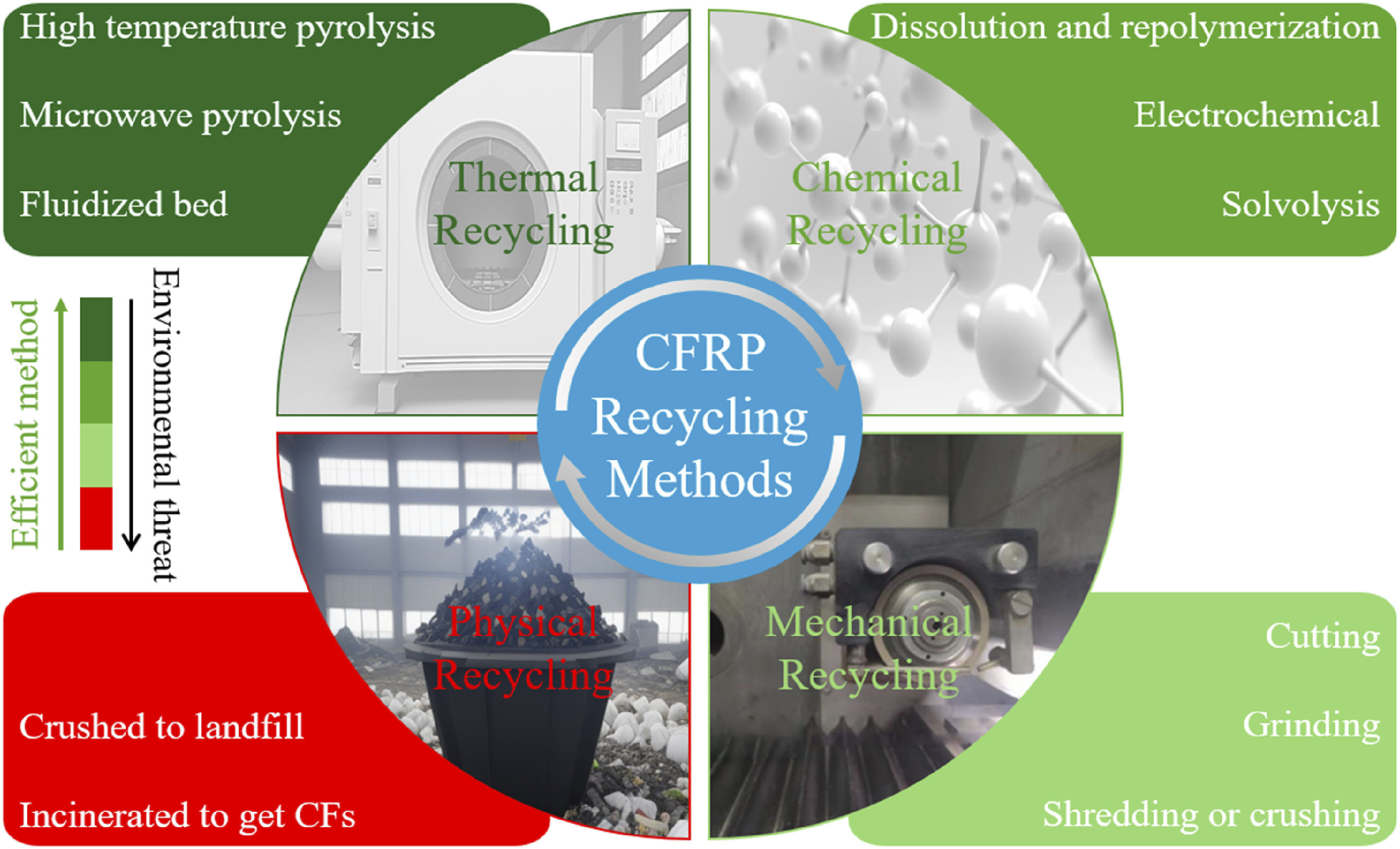
Moreover, extensive machining and thermal operations deteriorate the mechanical properties of recyclates. 21 Few studies adopted mechanical treatment for recycling CFRP composites.22–24 Contrary to mechanical recycling, physical recycling encompasses traditional disposal methods like landfilling and incineration, which contribute to waste accumulation and fail to capitalize on the valuable properties of composite materials. Incineration for energy recovery has a lower ecological impact than landfilling due to avoiding long-term methane gas release, which is 25 times stronger than carbon dioxide. 25 Therefore, the physical recycling approach is not an environmentally friendly and sustainable solution.26,27
Thermal recycling parameters from recent studies.
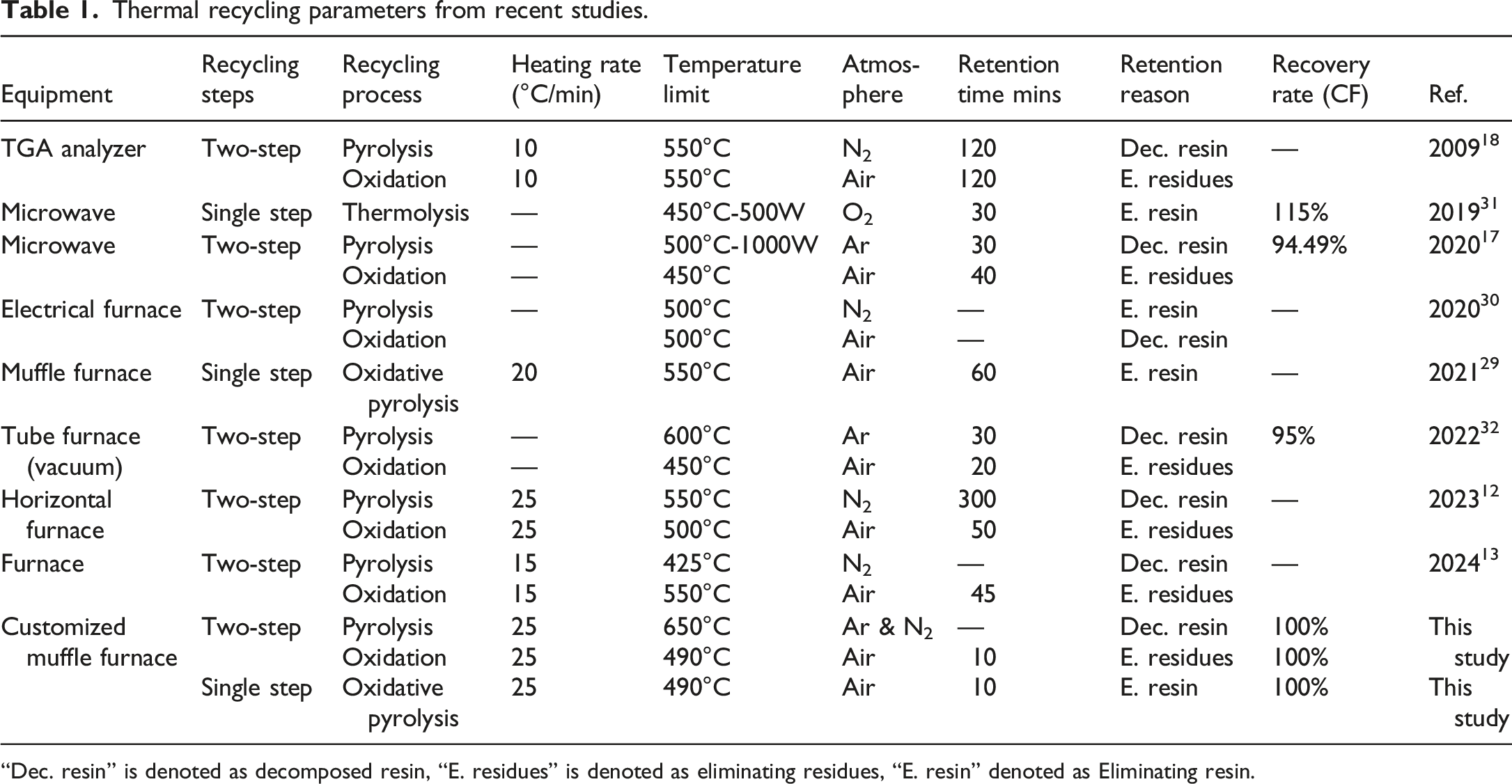
“Dec. resin” is denoted as decomposed resin, “E. residues” is denoted as eliminating residues, “E. resin” denoted as Eliminating resin.
The thermal recycling parameters vary in previous studies, and CFRP exposure to heat in the oxygen-containing atmosphere without optimized parameters may reduce the quality of recyclates. Therefore, this study aims to improve the quality of recycled carbon fibers with increased efficiency. To this aim, pilot experiments are carried out before thermal recycling to determine the optimized recycling parameters, such as variation of heating rates, temperature limits, gaseous atmospheres, kinetic behavior, and mass change. Furthermore, pyrolysis with two steps under an argon/nitrogen atmosphere and a single step under an air atmosphere is presented and compared regarding recyclability ratio and the quality of recyclates.
Materials and methods
Materials
The CFRP composite used in the study consists of epoxy resin, 4,4′-Diaminodiphenylsulfone (DDS) curing agent, and T800-3K carbon fiber. The E-51 bisphenol A-type epoxy resin was used with the molecular formula given in Figure 3(a), having flash point and boiling point as 273.8 ± 30.1°C and 529.0 ± 50.0°C respectively. DDS curing agent was used with flash point and boiling points of 263.2 ± 25.9°C and 511.7 ± 35.0°C, respectively, the molecular formula is shown in Figure 3(b). While, T800-3K carbon fiber was used in composites with 72 wt% and a diameter of ∼7 µm, provided by Shandong Zhuoliou Carbon Fiber Composite Materials Co., Ltd. Molecular formula of (a) E-51 epoxy resin and (b) curing agent DDS.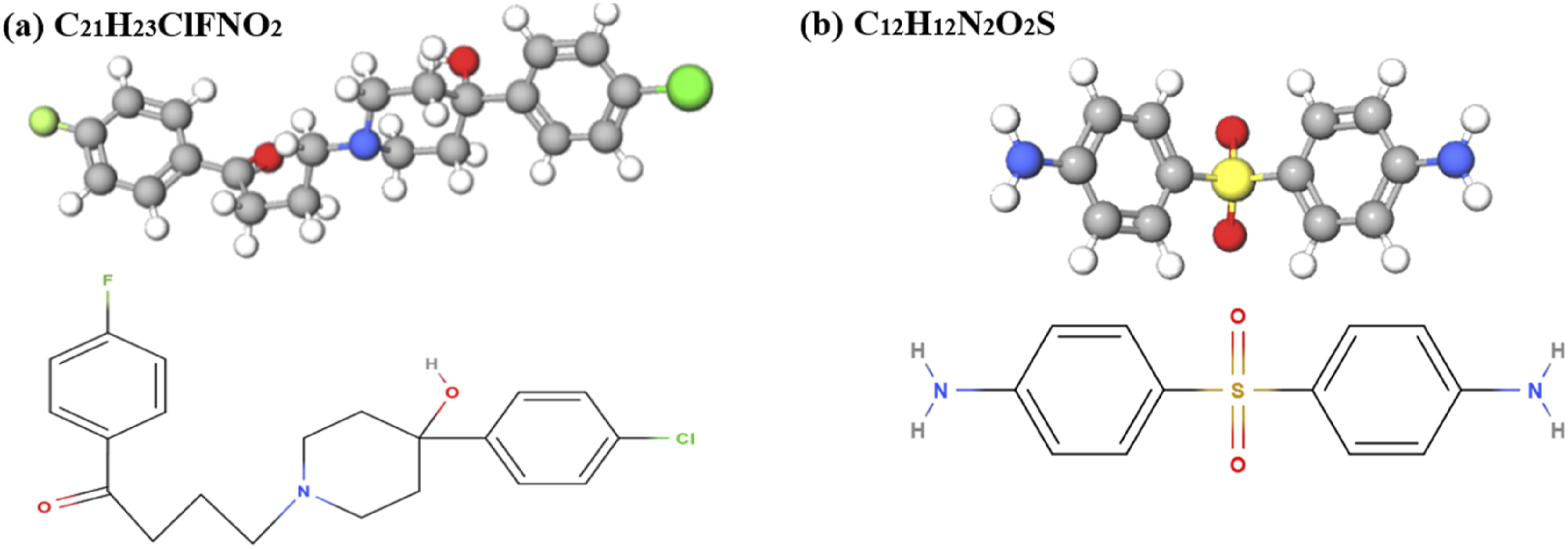
The CFRP composite have been manufactured from the fiber winding molding process as illustrated in Figure 4. First, E-51 epoxy resin is heated to 110°C, and the curing agent DDS is added to the heated epoxy resin to form a mixture of resin and curing agent. The ratio of epoxy resin to curing agent is 100:30. After immersing the reinforced carbon fiber in the prepared mixture, wrap it onto the core mold and place it in a preheated mold. Cure the carbon fiber and resin mixture after molding at a temperature and time of 100°C/30 min + 130°C/120 min + 180°C/180 min. After curing, wait for natural cooling to room temperature before demolding, and finally obtain CFRP. Fiber winding molding process diagram.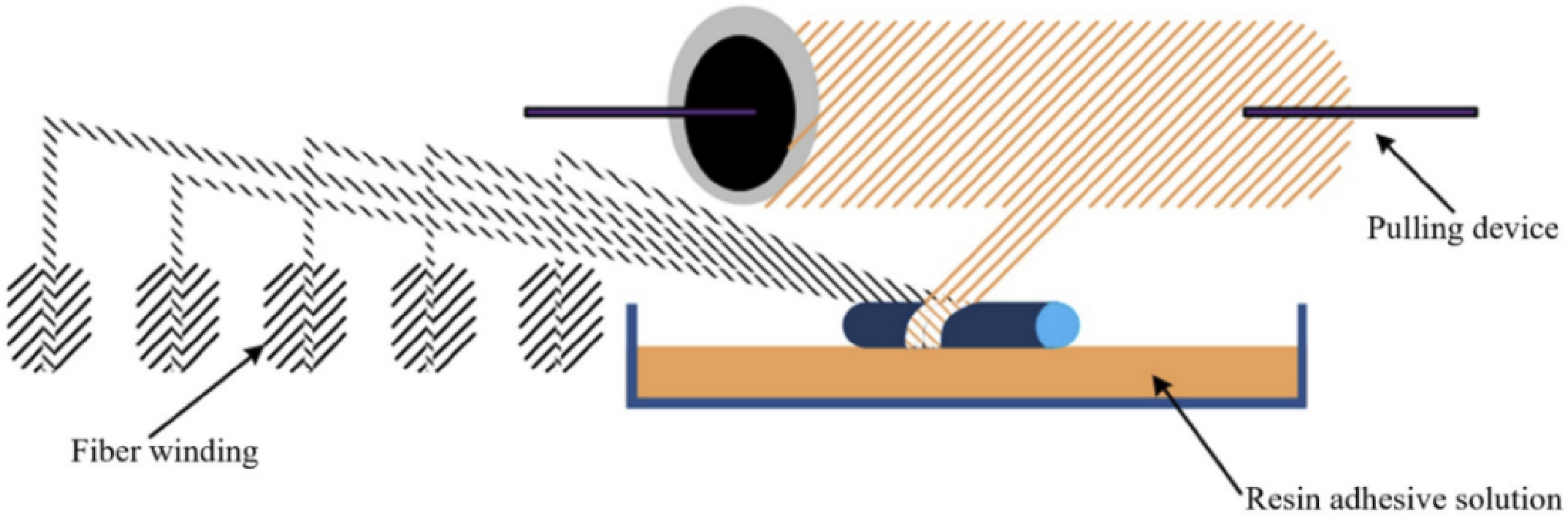
Methodology
The main obstacle in the thermal recycling method is the process parameters to achieve the reclaimed CFs quality near to virgin. Therefore, some pilot experiments are performed to identify the effective thermal degradation parameters that preserve the quality and mechanical properties of recycled CFs. Figure 5 demonstrates the structure of this study. Overview of the research workflow for CF recycling.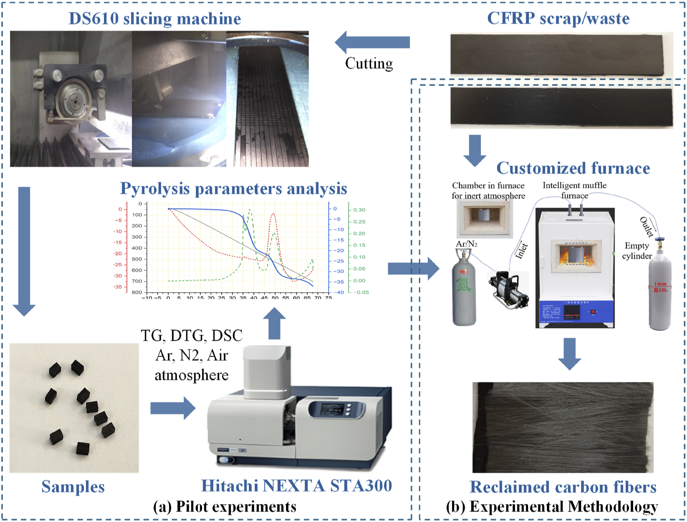
The pilot experiment was conducted to analyze the quality of CFs during the thermal degradation process and the effects of heating rates on thermal decomposition. The samples were extracted from the waste material, using a DS610 slicing machine to cut into dimensions with a width of 3 mm, length of 2 mm, and thickness of 2 mm; the weight of the samples was between 12 ± 0.5 mg. The samples were put in an air atmosphere using a Hitachi STA300 (thermogravimetric analyzer), record the data, and analyze the optimized process parameters for further experiments, as shown in Figure 5(a).
After pilot-experimental analysis, the samples from the unidirectional layered same CFRP waste were used and cut into random dimensional pieces of 23 ± 3 mm (length) × 14 ± 2 mm (width) × 2 mm (thickness), with a weight of between 1.9 ± 2 g. The author performed comparative experiments such as the single-step and two-step thermal recycling processes for the first time. The temperature range varies from 350°C to 700°C with an isothermal time of 10 min in nitrogen, argon, and air atmosphere; proceeded with the customized SX2-4-10A integrated intelligent muffle furnace. Later, measure its weight loss, observe the surface morphology through a scanning electron microscope (SEM) and optical microscopy, and examine the elemental composition of fibers by using an EDS energy spectrometer.
Pilot experiments
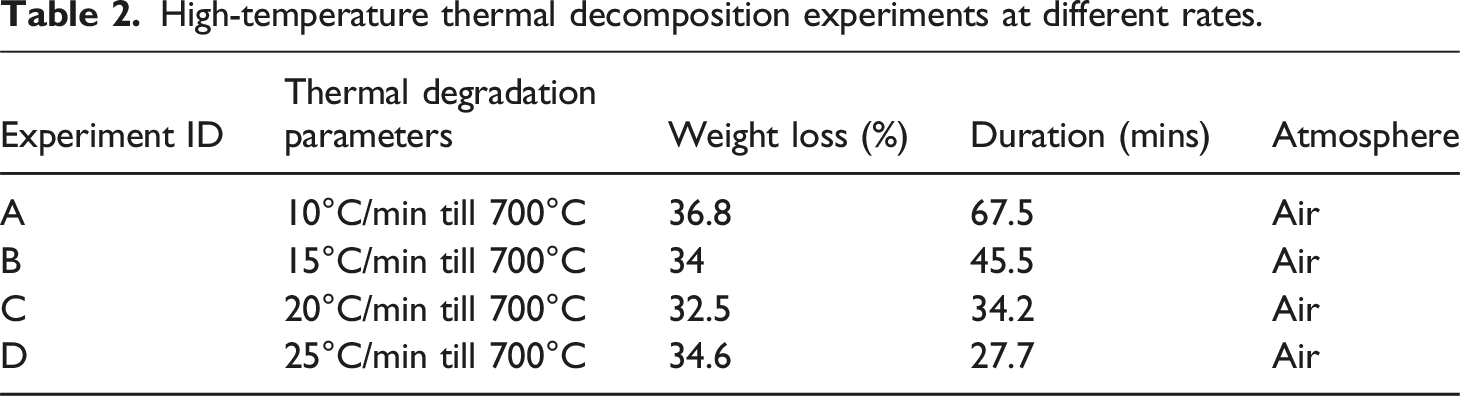
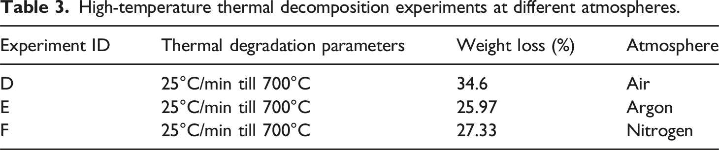
The pilot experiments were carried out to investigate the high-temperature thermal decomposition performance of CFRP at various heating rates of 10°C/min, 15°C/min, 20°C/min, and 25°C/min, and gaseous atmospheres like argon, nitrogen, and air. The temperature range of each group varies between 0°C and 700°C, which reveals one weight loss stage under an argon and nitrogen atmosphere, and three weight loss stages in an air atmosphere. The initial finding shows almost the same pattern of material degradation concerning temperature limits with minor changes in weight loss percentage.
High-temperature thermal decomposition experiments at different rates.
High-temperature thermal decomposition experiments at different atmospheres.
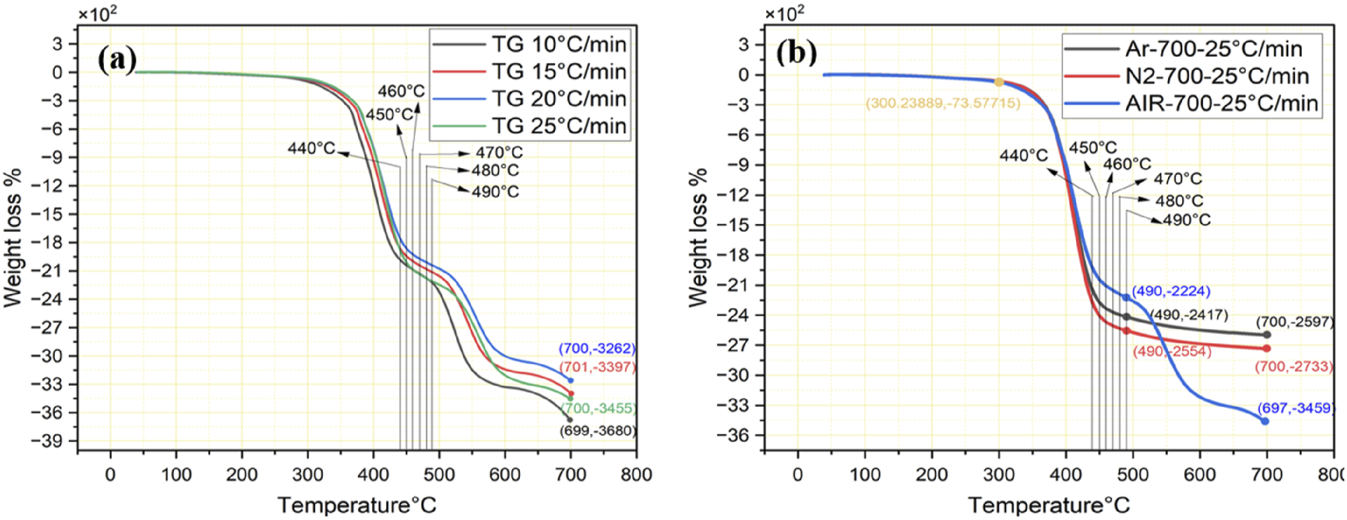
Influence of (a) heating rates under air atmosphere and (b) different atmospheres.
Consequently, investigations at a 25°C/min heating rate under the Argon and Nitrogen environment show only one stage of thermal weight loss in between the 300°C–490°C range as shown in Figure 6(b), continuing the heating does not even exceed 1.8% of weight loss till 700°C. However, oxidative pyrolysis under an air atmosphere shows three reaction segments, heating CFRP more than 490°C will cause the quality degradation of recycled CFs and affect the mechanical properties, these results are consistent with the findings of recent study. 33
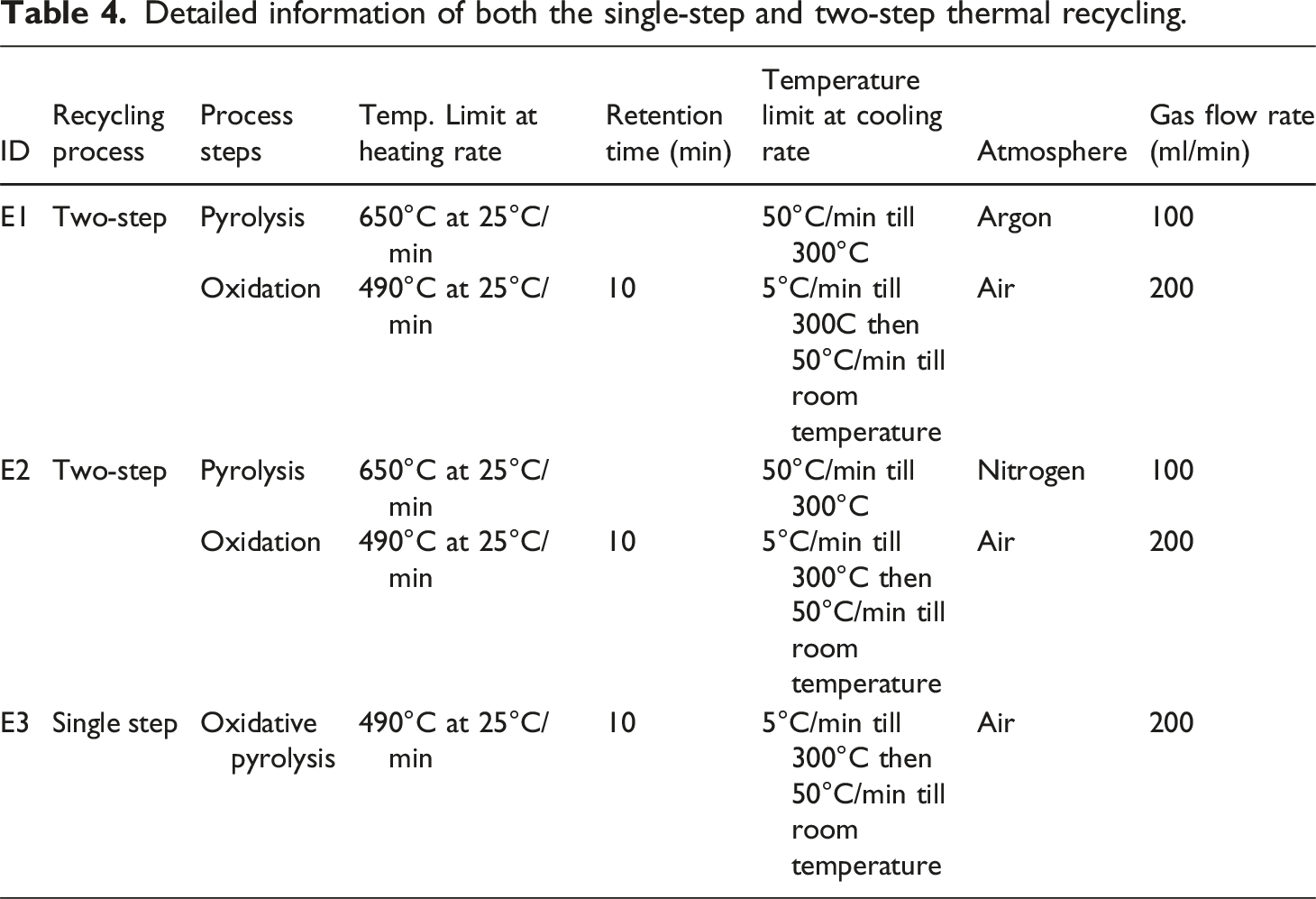
Detailed information of both the single-step and two-step thermal recycling.
The variation of resin-decomposed residues is calculated through the equation (1).
Following the findings of pilot experiments, the furnace was customized by integrating a gaseous atmosphere and embedding the chamber vessel inside. To ensure the complete displacement of nitrogen gas, the authors calculated the chamber volume as 78.5 mL. During the transition from an argon atmosphere to air, the mid-atmosphere of nitrogen was used to prevent combustion, then changing the atmosphere into air. The air is inlet at a controlled flow rate of 200 mL/min with a four-volume exchange, ensuring the complete displacement of N2 and minimizing the residual. At the same time, one cycle took approximately 2.5 min. The gas exchange was according to standard purging calculations. The concluded experimental IDs are listed in Table 4 as E1, which is two-step thermal recycling under argon atmosphere and oxidation under air atmosphere Ar650°C-Air490°C; E2, which corresponds to two-step thermal recycling under nitrogen atmosphere and oxidation in an air N 2 650°C-Air490°C; and E3 is single-step oxidative pyrolysis in an air atmosphere Air490°C.
In addition, to prevent the effects of temperature on gas density, especially during nitrogen and air atmospheric conditions. The authors replicated the gas flow rate of TGA during pilot experiments, which was 100 mL/min for argon and nitrogen atmosphere and 200 mL/min for air atmosphere, which supports the preliminary findings during the analysis. The gas flow meter for continuous gas flow maintenance was used, and detailed information is presented in Table 4, while the schematic of the setup is demonstrated in Figure 7. Schematic of customized muffle furnace.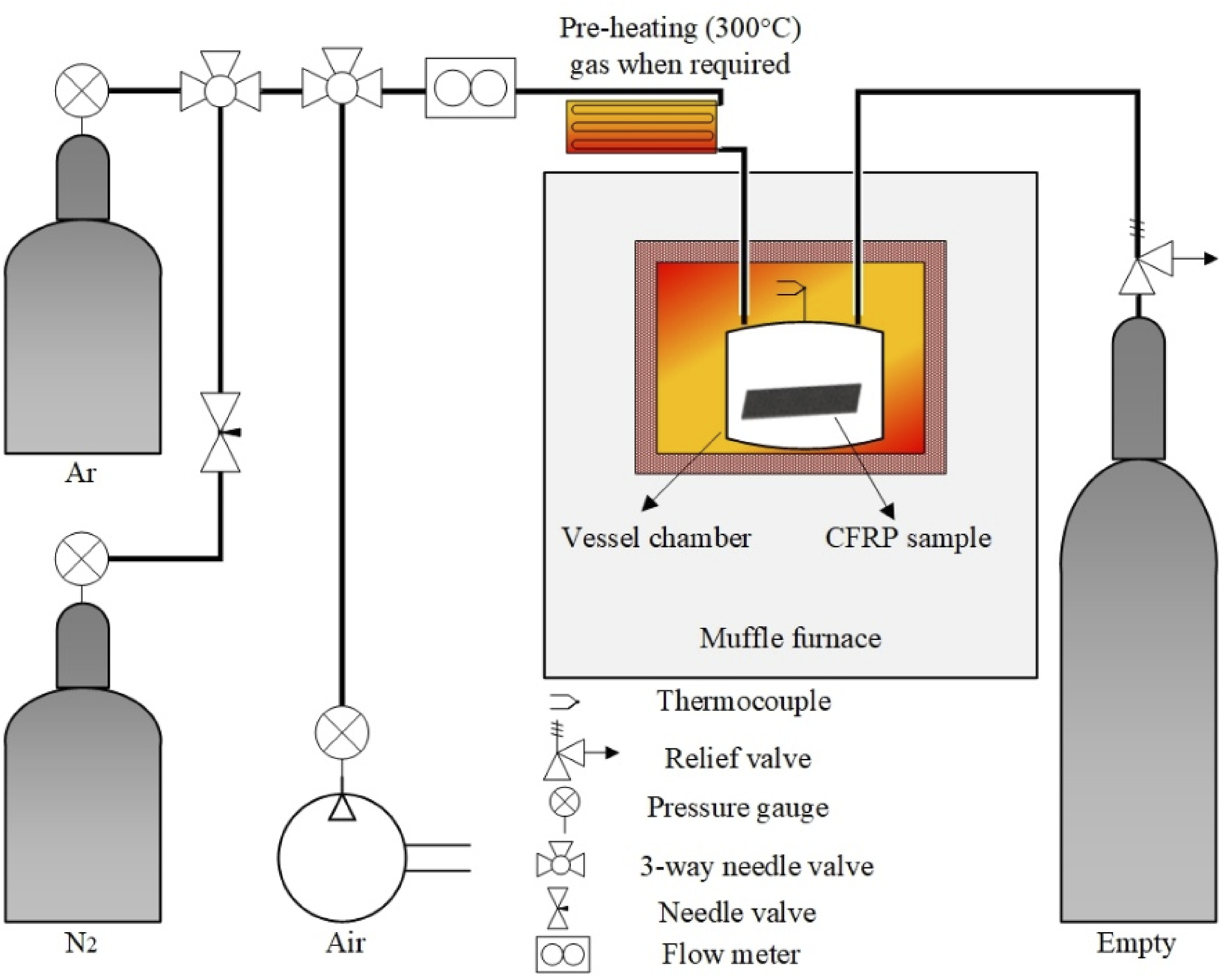
Mechanical properties investigation of recycled fibers
The tensile strength and modulus of single carbon fiber was tested by using the XQ-1C Fiber Tensile Tester from Shanghai New Fiber Instrument Co., Ltd. with a load range of 0 to 200 cN the speed was 1 mm/min. The fiber diameter was measured with SEM analysis and CF was carefully placed on a piece of paper (circle cut from the center) maintaining the gauge length and were attached with AB adhesive glue, paper-tape was attached on both end of specimen for the grip, the gauge length of 20 mm, and the length of specimen was 30 mm, the sample preparation is shown in Figure 8; after calibration and placing the sample in grips, testing began, and failure load was recorded, the average of 10 different fibers of each experimental approach is calculated through ASTM C1557-20 guidelines.
36
(a) Specimen demonstration for single-fiber tensile testing, (b) the actual specimen, (c) magnified image of the implanted CF, and (d) magnified image of the glue area bonding the CF and coupon.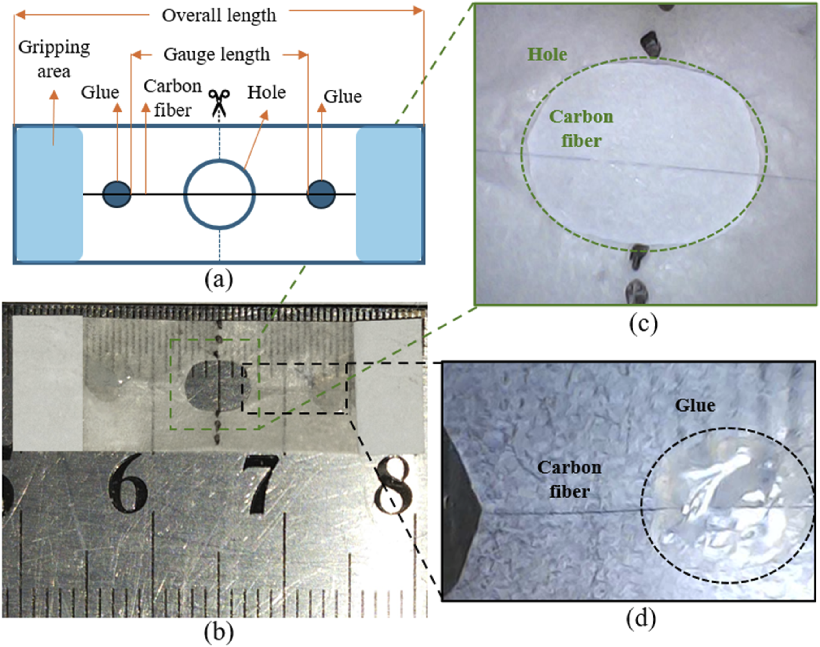
Results and discussion
Mechanism of thermal decomposition
During the thermal degradation process, the resin matrix undergoes a chemical reaction. Figure 9(a) is a schematic diagram of the molecular structure of the resin matrix after cross-linking; the red part shows carbon and nitrogen, where the chain is breaking. The reaction process then forms five types of small molecular chains, as shown in Figure 9(b); these small molecules combine again by absorbing energy during the thermal degradation process and finally form new substances. The five different small molecular chains formed after the carbon-nitrogen chain scission reaction react again to create a variety of substances by absorbing the energy generated by the chain scission. The energy this reaction provides increases as the pyrolysis temperature rises, and the higher the temperature during the thermal degradation process, the more complex the molecular structure of the new substances produced. (a) Reaction principle during thermal degradation process and (b) five main types of small molecules.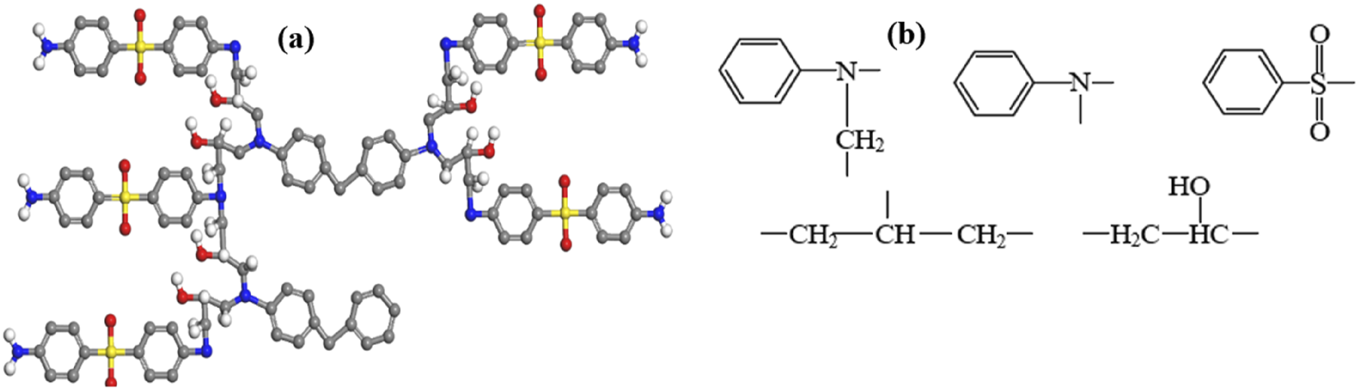
The thermal recycling method utilizes the high-temperature resistance of reinforced fibers. The epoxy resin in the crucible is melted at high temperatures to extract carbon fibers. The resin matrix is decomposed into low-molecular-weight molecules, resulting in small-molecule products such as tar, CO2, H2, CH4, etc. The solid residues are char, inorganic fillers, reinforced fibers, carbonaceous layer, and a small residual carbon. 37 This recycling approach can recycle the vast majority of waste, including CFRP waste and GFRP composite waste materials, 38 and maintain the good mechanical properties of carbon fiber, which can recycle a large amount of waste at once.
Influence of heating rates on thermal degradation process
Carbon fiber exposure to high temperatures in an oxygen-containing atmosphere shows three segments of reaction: resin degradation, oxidative resin residue elimination along with oxidation of carbon fibers, and further oxidation of carbon fibers to mass loss. To investigate the kinetic behavior of material degradation in the context of TGA, the Arrhenius kinetics analysis assists in analyzing activation energy for opposing processes, kinetic behavior, and thermal transitions that occur during thermal decomposition process, assisting in determining the yield point of opposite reaction,
13
as shown in equation (2).
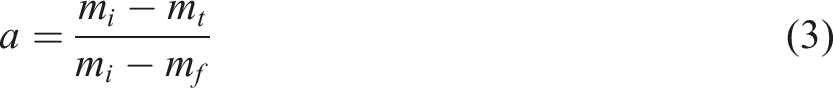
Figure 10 shows two thermal weight losses and two peaks in the DTG curve, corresponding to two different oxidation reactions. The first weight loss occurs when the resin matrix melts between 300°C and 460°C, breaking chemical bonds in the air atmosphere, while the second weight loss occurs when pyrolytic carbon and oxygen react between 460°C and 580°C, causing CF’s diameter and structural integrity degradation. The temperature limit above 564°C∼607°C continues the oxidation reaction and mass decline of CFs; that trend line stopped due to the temperature limit of 700°C, leading to a further weight loss of CFs. The CFRP thermal degradation at 10°C/min decomposes resin matrix at the rate of mass loss is dm/dt = 0.303 mg/min at the peak around 38 min; at 15°C/min, the rate of mass loss is dm/dt = 0.463 mg/min at around 27 min, at 20°C/min it is dm/dt = 0.565 mg/min at around 20 min, and at 25°C/min is dm/dt = 0.814 mg/min at around 17 min. However, the temperature between 300°C and 460°C causes a significant drop due to the resin degradation; this reaction slightly varies against heating rates. The negative activation energy (DSC curve) was observed at 464°C under 10°C/min in Figure 10(a), 475°C at 15°C/min in Figure 10(b), 481°C at the rate of 20°C/min in Figure 10(c), and 491°C at the rate of 25°C/min in Figure 10(d), which means endothermic reaction had stopped and increasing the temperature may cause the quality degradation of CFs, reducing diameter, and produce pits on the surface. TG, DTG, and DSC of CFRP at different heating rates, (a) 10°C/min, (b) 15°C/min, (c) 20°C/min, and (d) 25°C/min.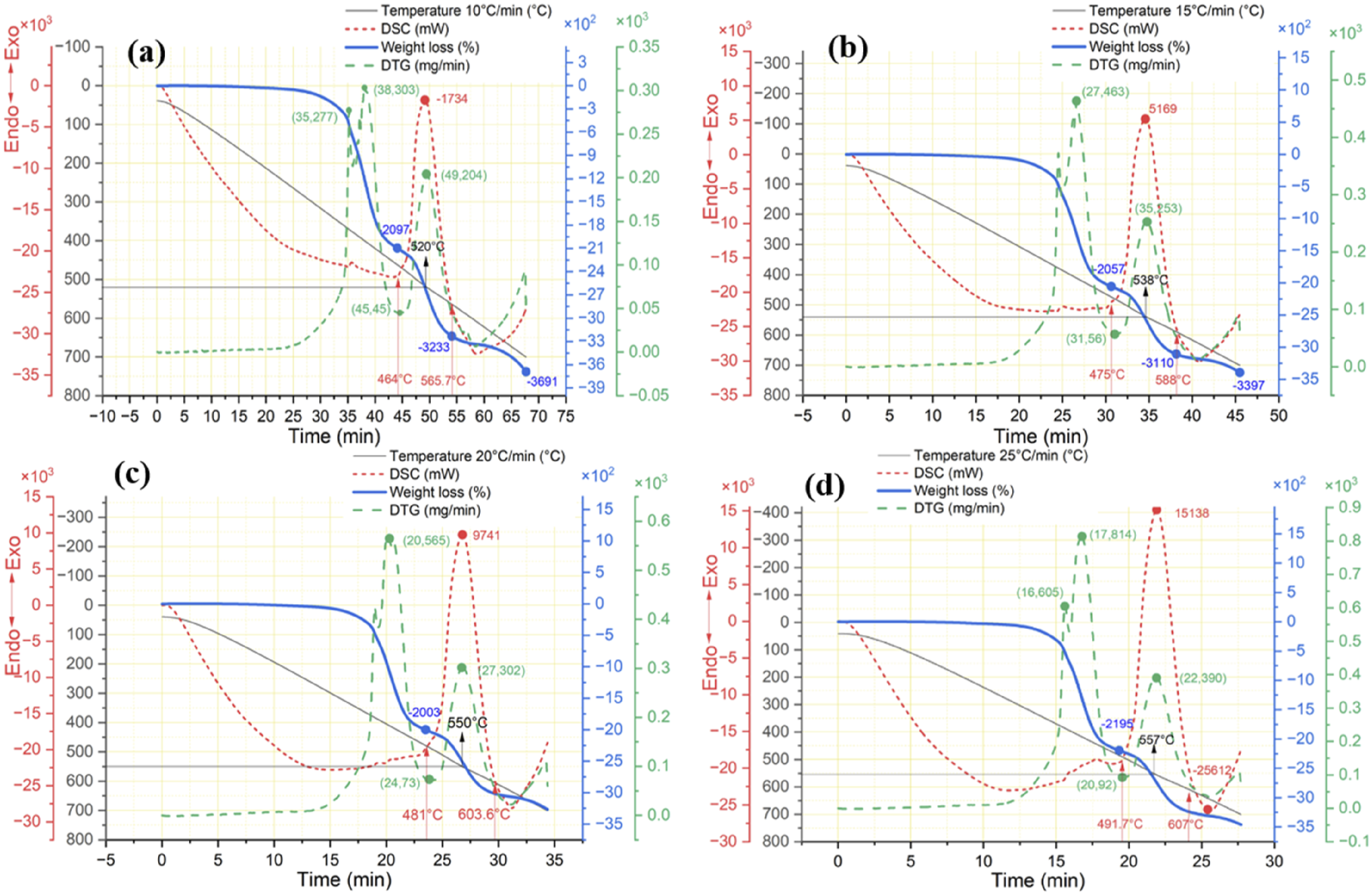
Regardless of the heating rate used for thermal recycling, the CFRP mass decreases in a similar pattern proportional to the temperature, with a variation of 27°C.
Comparing the data in Figure 6 shows that atmospheric conditions have minimum effects on thermal decomposition below 490°C regardless of heating rates. Oxidative pyrolysis of CFRP under air atmosphere section demonstrates the impact of heating limit ranging from 440°C to 490°C with an isothermal time of 10 min in an air atmosphere.
Influence of gaseous atmospheres during the thermal degradation process
The influence of variable atmosphere is analyzed as gas atmospheres affect the quality and surface of CFs. For instance, argon atmospheres reveal a carbonaceous layer, while nitrogen atmospheres produce a carbonaceous layer and minor residues. However, the air atmosphere continuously reacts and oxidizes with increasing temperature, reducing the quality. The thermal degradation process parameters are selected based on pilot experiments, as described in pilot experiments section.
Oxidative pyrolysis of CFRP under air atmosphere
The optimum temperature range for oxidative pyrolysis of CFRP in an air atmosphere is 480–490°C at the rate of 25°C/min. Increasing the temperature limit may cause the quality degradation of CFs and produce craters or shallow pits on the surface of CFs due to the oxidation of stuck pyrolytic carbon and reducing the diameters of CFs. To avoid such damages, the author set the isothermal time of 10 min to clean the surface of CFs from pyrolytic residues with minimum damage, as it assists in burning off the residues and oxidizing them into gaseous products such as carbon dioxide and carbon monoxide. The cooling rate of 5°C per minute is essential to reduce the temperature of recyclates to 300°C. Then, adjust the cooling rate to 50°C per minute until room temperature. This process helps to preserve the quality of carbon fibers by mitigating thermal shocks, which can cause shallow pits and surface damage. Additionally, it facilitates the smooth rearrangement of the carbon chains. Figure 11 illustrates the decomposed resin residue removal trend, showing significant changes within the temperature range of 440°C to 490°C, as depicted in the SEM images. SEM surface morphology of CFRP in an air atmosphere.
Comparison of weight loss% with/without isothermal time and cooling rate (air).
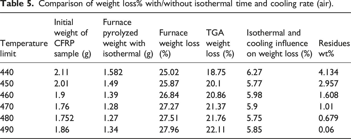
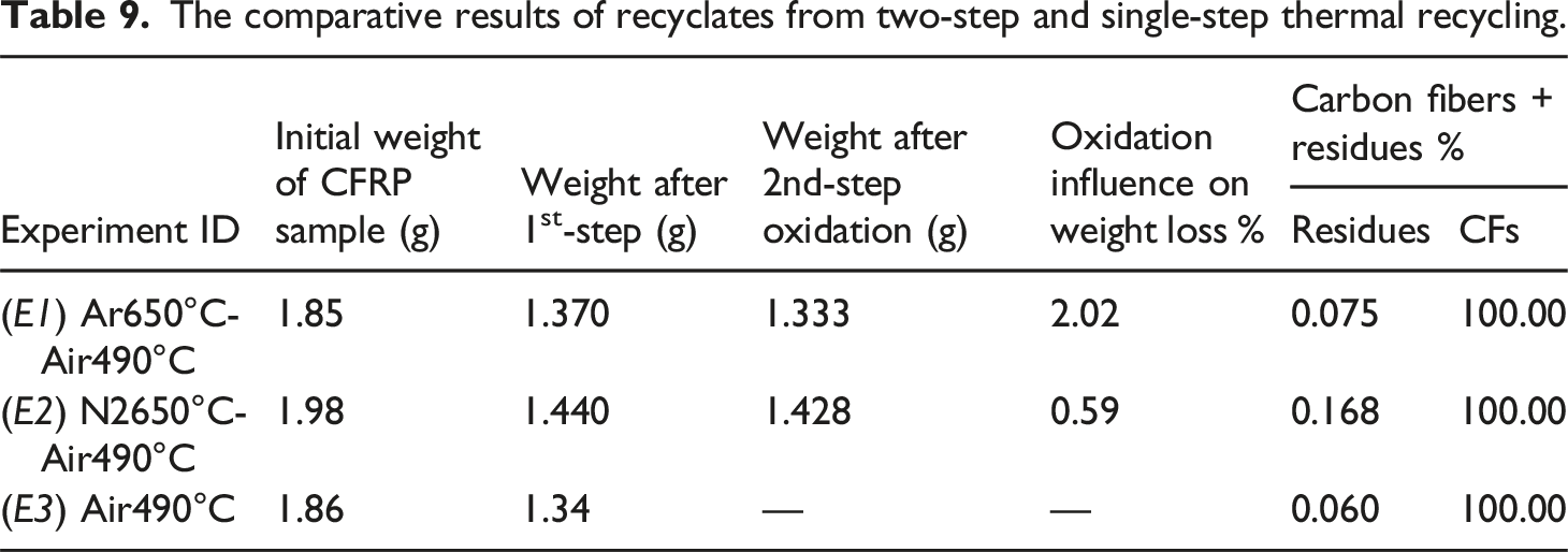
Table 5 shows the CFRP weight loss % comparison between the furnace with a holding time of 10 min and the Hitachi STA300 TGA without a holding time during thermal recycling. Carbon fibers at 490°C achieved 100% reclamation with negligible pyrolytic residue contamination of 0.06%. The amount of CFs in used CFRP samples is approximately 100% because the carbon fibers don’t degrade below the temperature of 490°C at 25°C/min. The variation of resin-decomposed residues is further calculated, as shown in equation (1).
High-temperature pyrolysis of CFRP under argon atmosphere
The thermal degradation of CFRP under an argon atmosphere shows only one reaction: resin decomposition. Significant weight loss has occurred from the temperature range of 308°C – 490°C. The range decomposes the resin matrix and forms the carbonaceous layer on the surface of CFs. The DTG graph shows the peak of 0.965 mg/min rate of weight loss at 410°C. At the same time, the amount of heat (energy) in this endothermic reaction is consumed 11.35 mJ/mg in the range of 384°C to 460°C then heat absorption is uniform till around 600°C; after this limit, the smooth pattern of heat absorption continues at the same rate. CFRP pyrolysis under argon atmosphere in the range of 490°C–700°C gradually reduces the carbonaceous layer and pyrolytic residues. This range shows only 1.8% weight loss and the activation energy shows minor thermal degradation as shown in Figures 6(b) and 12. Continuing the heat increase till 630°C reduces the 25.66% weight of CFRP, which does not affect the quality of carbon fiber due to the protective layer. Thermal gravimetric analysis of CFRP under argon atmosphere.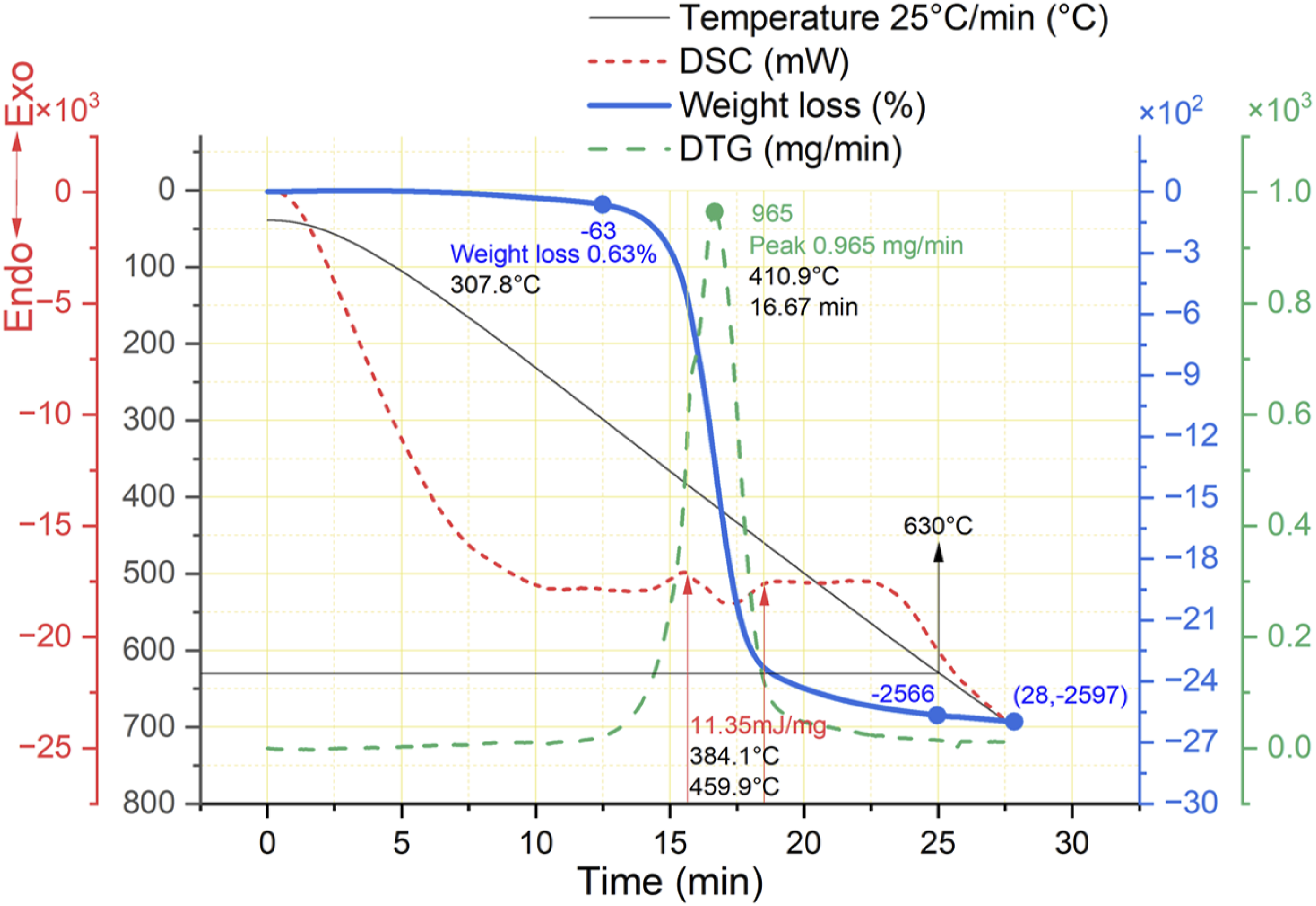
Figure 13 depicts the SEM and optical visuals at different temperature limits: 550°C, 600°C, 650°C, and 700°C. The surface morphology analyzed through optical and SEM microscopy provides better insights for understating the surface quality and damage. During thermal pyrolysis in an argon atmosphere till 490°C, CFs are stuck together due to the carbonaceous layer; this layer further decomposes and produces char as temperature increases and partially separates the fibers. For instance, at 550°C, Figure 13(a) shows a significant amount of char residues and sticking of carbon fibers due to the carbonaceous layer. At 600°C, it reduces the amount of char and partially decomposes the layer, separating the carbon fibers, as seen in Figure 13(b). Further increasing the temperature to 650°C and 700°C follow the same phenomenon and peel off the layer besides residue decomposition, as shown in Figure 13(c) and (d). This residue elimination correlates with a minor weight loss of 1.8% within this range, as mentioned above. SEM and optical microscopy of CFRP thermal degradation (Ar), (a) till 550°C, (b) till 600°C, (c) till 650°C, and (d) till 700°C.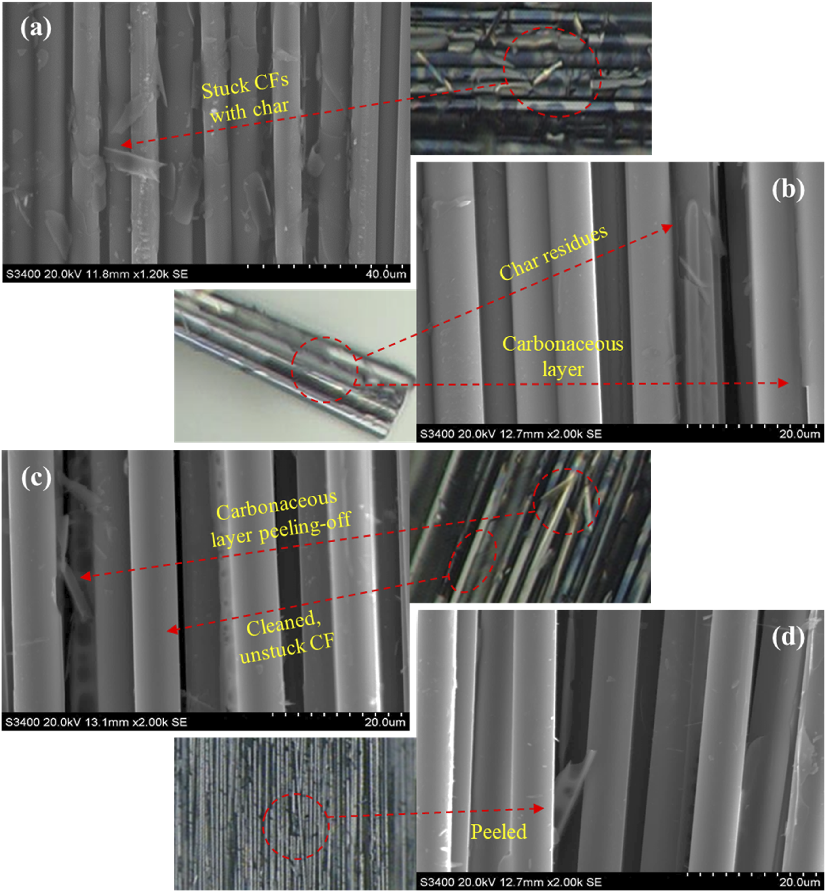
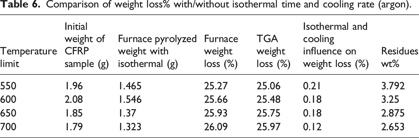
Comparison of weight loss% with/without isothermal time and cooling rate (argon).
High-temperature pyrolysis of CFRP under nitrogen atmosphere
The thermal degradation of CFRP under a nitrogen atmosphere shows resin decomposition like argon atmosphere. However, the reaction begins a little earlier at 302°C and ends at 490°C as compared to Figures 6(b) and 14. This temperature range brings significant weight loss while decomposing the resin matrix, forming the carbonaceous layer on the surface of CFs. While producing minor pyrolytic residues containing “O” and “Si” elements. The DTG graph shows the peak of 1.039 mg/min rate of weight loss at 412°C, which is a little faster than the argon atmosphere. In comparison, this endothermic reaction’s amount of heat (energy) is also increased to 17.01 mJ/mg in the range of 385°C to 466°C. Further exposure of CFRP with increasing temperatures like 490°C–700°C gradually reduces the amount of carbonaceous layer and pyrolytic residues. This range is similar to the argon atmosphere and shows only 1.8% weight loss. The activation energy shows a smooth thermal degradation pattern, which means the oxidation of residues is still required in both atmospheres, continuing the heat increase till 625°C does not affect the quality of carbon fibers. Thermal weight loss of CFRP in a nitrogen atmosphere.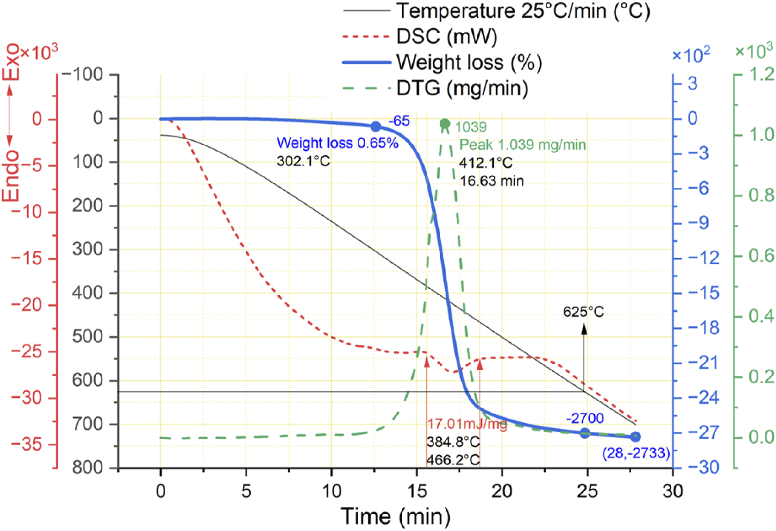
Figure 15 illustrates the SEM and optical visuals at different temperature limits such as 550°C, 600°C, 650°C, and 700°C. As shown in Figure 15(a) and (b), the surface morphology of CFs is slightly different from that of pyrolysis in an argon atmosphere; the carbonaceous layer comparatively forms a strong stickiness of fibers until 600°C. After this limit, the fibers are partially separated, with some residues from the carbonaceous layer peeling off as shown in Figure 15(c) and (d). SEM and optical microscopy of CFRP thermal degradation (N2), (a) till 550°C, (b) till 600°C, (c) till 650°C, and (d) till 700°C.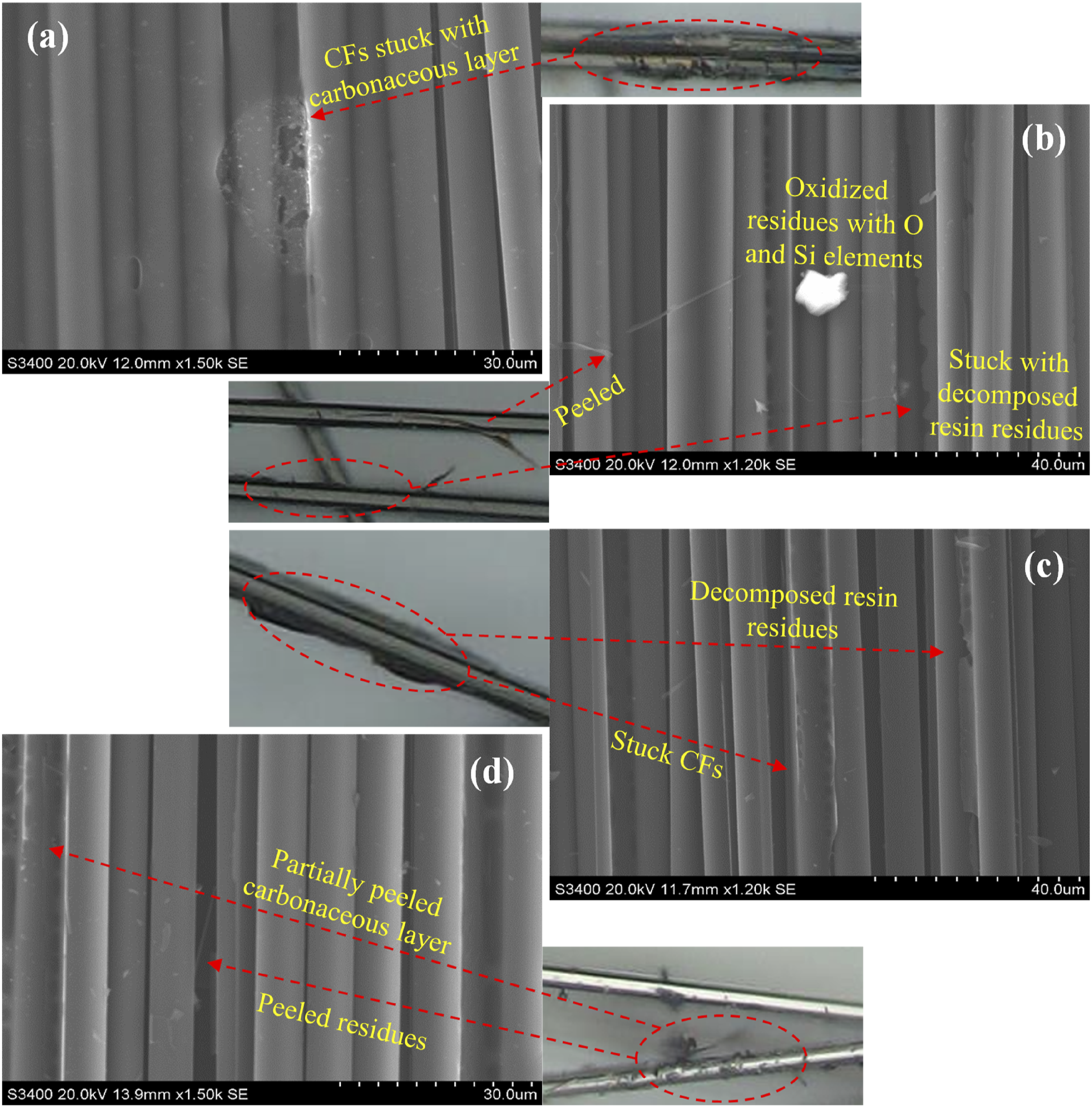
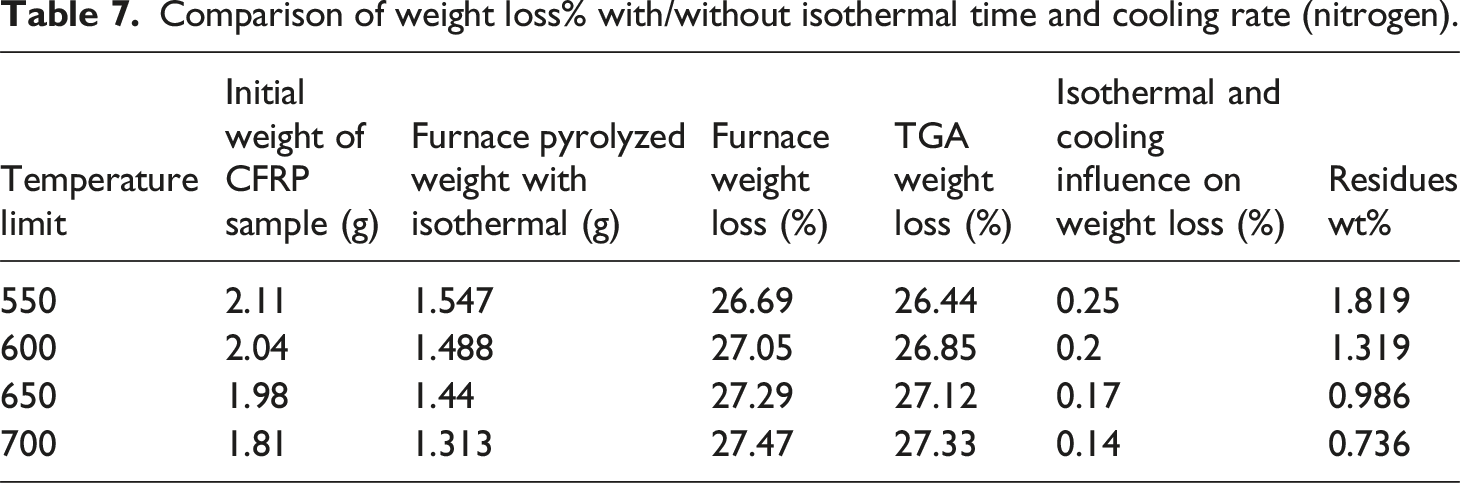
Comparison of weight loss% with/without isothermal time and cooling rate (nitrogen).
Considering the quality of recyclates under an argon and nitrogen atmosphere, the second oxidation step is required to achieve clean CFs. However, only a single step of oxidative pyrolysis can achieve near to similar results in an air atmosphere compared to two-step that is pyrolysis and oxidation. Consequently, the author attempted to recycle CFRP through both processes while comparing the data to optimize parameters for better results.
Comparison and characterization of two-step and single-step thermal recycling
A two-step method was adopted for the thermal recycling of CFRP that starts with first-step of pyrolysis in an N2/Ar atmosphere followed by second-step that involves oxidation in an air atmosphere to burn off the carbonaceous and char residues followed by their oxidation into gaseous products. Analysis of Figures 12 and 13 shows that there is still pyrolytic carbon even when heated to 650°C in an argon or nitrogen atmosphere; by comparing the change trends in Figure 11, the carbon fibers are separated after the removal of epoxy resin and pyrolytic carbon when heated to 490°C in an air atmosphere with an isothermal time. Therefore, CFRP is first pyrolyzed in an argon and nitrogen atmosphere to 650°C to remove the resin matrix without isothermal time, followed by CFRP oxidation in an air atmosphere at 490°C with isothermal and cooling rate factors to remove the residues from the surface of CFs. Alternatively, the analysis of section 3.3 shows positive results for thermal recycling through a single-step process, the comparative visuals of two-step thermal recycling process under both environments and single-step oxidative pyrolysis under air atmosphere are shown in Figure 16. SEM and optical microscopy comparison of two-step and single-step thermal recycling process, (a) two-step E1, (b) two-step E2, and (c) single-step E3.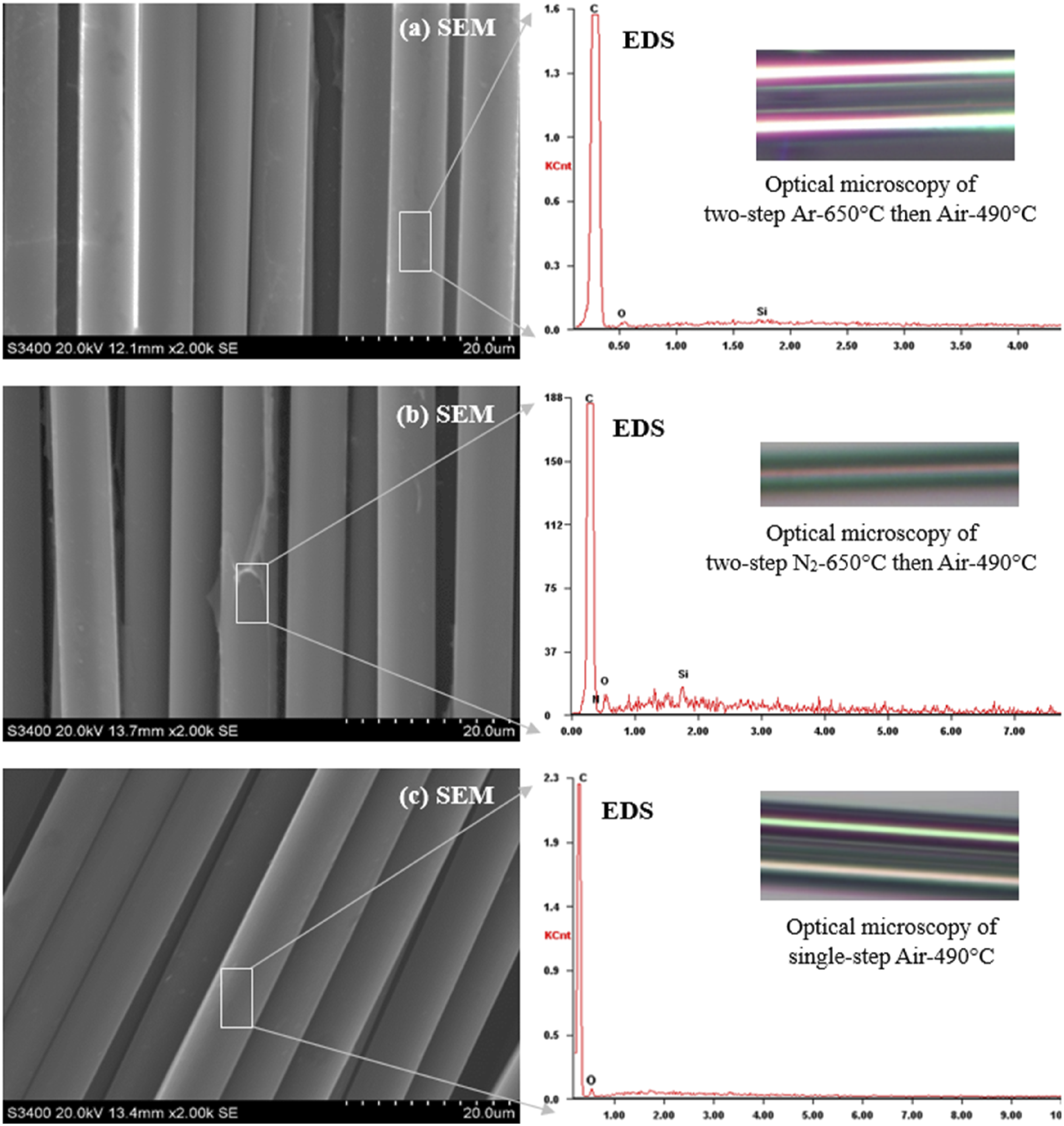
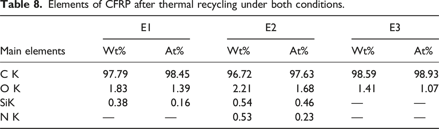
Elements of CFRP after thermal recycling under both conditions.
The comparative results of recyclates from two-step and single-step thermal recycling.
The mechanical properties vary in each category, with the least of 81.03% and 83.65% of tensile strength and modulus, respectively, which may be used to remanufacture advanced composites where structural and flexural properties are sensitive. Figure 17 shows the average tensile strength of virgin CF samples that is 2882.1 MPa. While, E1, E2, and E3 were 2409.37 MPa, 2363.66 MPa, and 2335.39 MPa, respectively. The average tensile modulus of virgin carbon fibers was 222.02 GPa, while, E1, E2, and E3 were 191.99 GPa, 185.87 GPa, and 185.7 GPa, respectively. Comparison of single fiber tensile testing (a) tensile strength and (b) tensile modulus.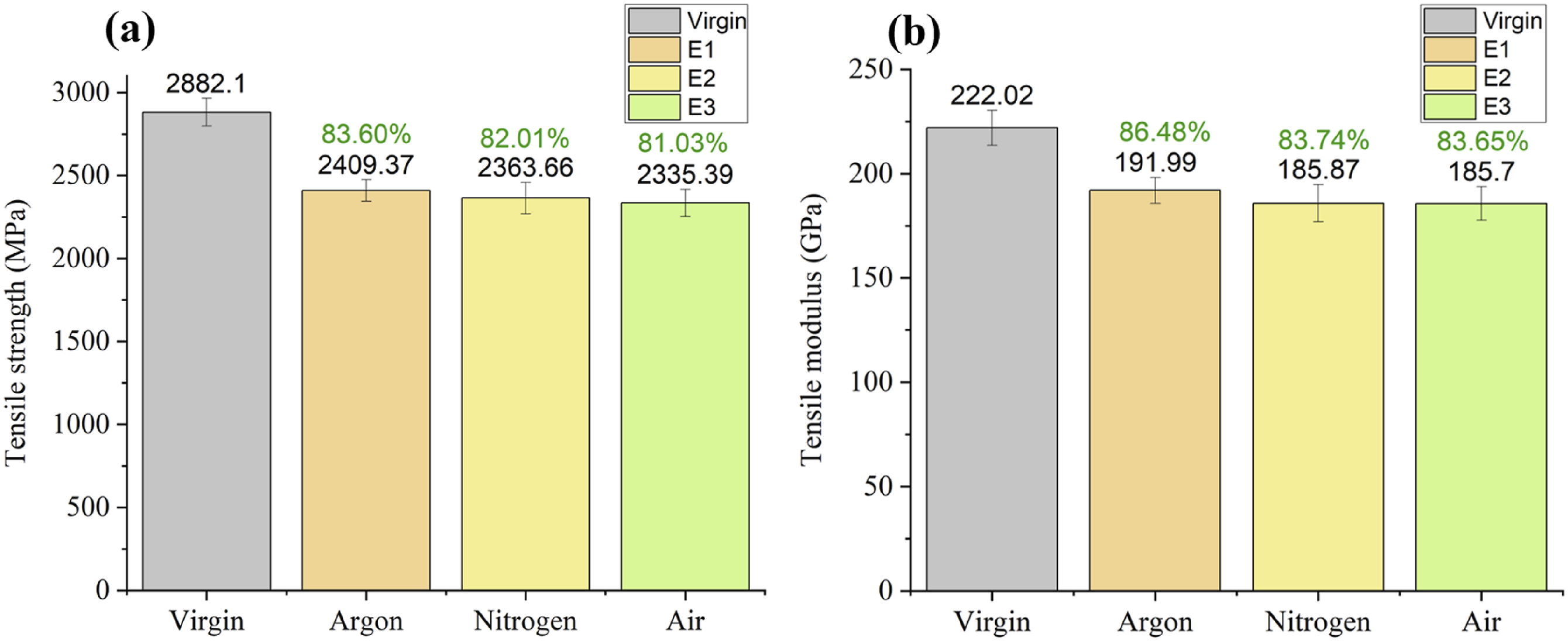
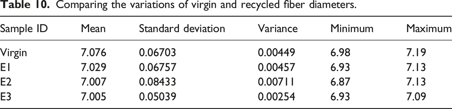
Figure 18 depicts the final appearance of CFRP after thermal recycling; reclaimed carbon fibers’ chemical composition and surface morphology are similar to those of virgin fibers. The process parameters used in thermal recycling do not significantly affect the fibers’ diameter and length. The variations of virgin and recycled (from E1, E2, E3) CF diameters are reported in Table 10, with a sample size of 10 from each category. Appearance of reclaimed CFs through optimized process parameters: 25°C/min, isothermal 10 min, colling 5°C/min till 300°C then 50°C/min cooling rate. (a) Two-step E1 (b) two-step E2, and (c) single-step E3. Comparing the variations of virgin and recycled fiber diameters.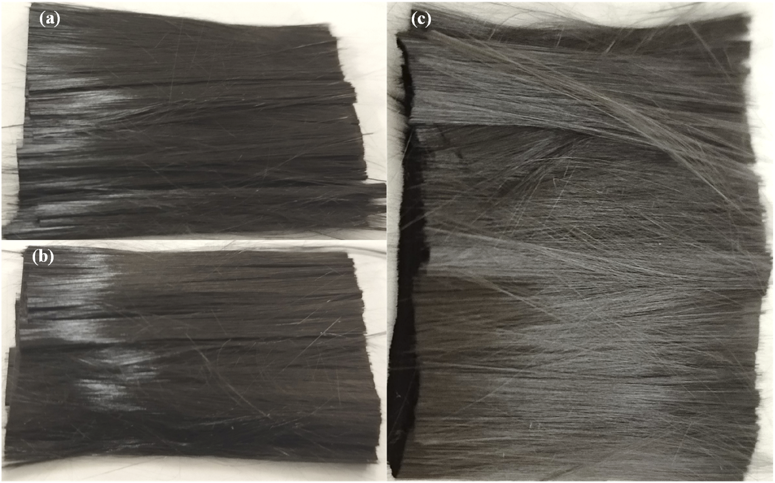
This study successfully recycled carbon fibers while retaining their original lengths from the waste component. This advancement paves the way for additive manufacturing research to utilize these recyclates in producing new CFRP components. Alternatively, these CFs might couple with virgin epoxy resin solution to form CFRP composite components through traditional manufacturing methods such as forging or resin transfer molding (RTM).
Conclusion
This study investigated the high-temperature thermal recycling process under optimized parameters along with a comparative experiment between single-step and two-step methods during thermal recycling. Pilot experimental analysis was performed using TGA to evaluate the effect of heating rate and different atmospheres on thermal degradation, a customized muffle furnace was used for reclaiming CFs from CFRP waste followed by surface morphology analysis, chemical composition, and mechanical properties testing. The main findings are as follows: • A single-step and two-step thermal recycling processes both achieved 100% reclamation of clean CFs having surface quality near to virgin with a fiber’s diameter difference of ±0.12 μm. The process parameters for single-step oxidative pyrolysis (E3) are heating the CFRP waste at 25°C/min till 480–490°C, holding the limits for 10 min, followed by sequential cooling, first at 5°C/min till 300°C, then at 50°C/min till room temperature preserving CFs from surface damages that is, thermal shocks and pits. The whole process finishes in almost 1.25 h. Although heating rates below 25°C/min had little effect on the weight loss of CFRP during recycling, the reaction completion time decreases as the heating rate increases. However, isothermal dwelling time after reaching the temperature limit and sequential cooling in an oxygen-containing atmosphere significantly influences the degradation process of CFRP. • On the contrary, the optimized parameters for the two-step include pyrolyzing the CFRP under an argon and nitrogen atmosphere (E2 and E3) till 650°C at 25°C/min heating rate, then cooling at 50°C/min till 300°C. Then change the atmosphere into the air for oxidation at 25°C/min heating rate till 490°C, leaving it for 10 min followed by sequential cooling, first at 5°C/min till 300°C then at 50°C/min till room temperature. The entire recycling process takes less than 2 h. However, isothermal time does not influence the CFRP under argon and nitrogen atmospheres. • Regarding the quality of reclaimed carbon fibers, a two-step E1 have better properties than those of two-step E2 and a single-step E3. However, the CFs reclaimed through E3 are cost effective. While, CFs obtained from E2 and E3 can be treated and improved chemically, like acid etching or applying a suitable sizing agent before applying the resin matrix and remanufacturing the composite component. The thermal recycling parameters used in this study are applicable for composites made from A-stage materials (resin in raw/uncured state and dry CFs). In contrast, a two-step thermal recycling process can be applied to recycle thermoplastic composites. However, the recycling output of thermoset composites made from B-stage prepreg (partially cured resin with CFs, laminate prepreg) may differ. • The surface of reclaimed carbon fibers from both processes shows functional groups, which are beneficial for adhesive properties. The concluded tensile strengths are E1-83.6%, E2-82.01%, E3-81.03% and tensile modulus are E1-86.48%, E2-83.74%, E3-83.65%. Although, the difference in reclaimed CFs is not big, E1 process is recommended for CFRP based on thermoset composite due to the rationality between process simplicity and recyclates output. In addition, CFRP based on thermoplastics, the E1 process is recommended due to the quality preferences.
Further studies will continue to recycle CFRP using the optimized parameters and remanufacture composite material using virgin epoxy and CF recyclates through traditional RTM and additive manufacturing approaches.
Footnotes
Declaration of conflicting interests
The author(s) declared no potential conflicts of interest with respect to the research, authorship, and/or publication of this article.
Funding
This research was funded by National Natural Science Foundation of China (No. 52275455), Science and Technology Plan Project of Liaoning Province, China (grant number 2022TH1/10800081).
Data Availability Statement
Data available on request from the authors.