
Abstract
Processing of specialized flexible conductive components has drawn a lot of attention as the electronic component industry is moving towards intelligence and wearability. The processing of flexible, custom-made conductive components has recently become a key objective. Additionally, additive manufacturing has emerged as a crucial method. The viability of producing a composite material out of graphene oxide (GO) and thermoplastic polyurethane (TPU) using the laser sintering (LS) technology was established in this work. Following the carbonization treatment on the entire GO/TPU LS portion, the evolution of the matching microstructure was seen, and both dimensional variation and electrical conductivity were examined in the study. Effects of the GO content in the composite powders on the thermal stability, dimensional appearance, and electrical conductivity of carbonized parts were gradually revealed. Additionally, it was explained how the carbonization temperature affected the electrical conductivity of the carbonized GO/TPU portion. The experimental findings showed that the carbonized portion of the GO/TPU composite material had excellent electrical conductivity when the GO content reached 2.5 wt% and the carbonization temperature was set at 800°C. The surface electrical resistivity of the part was calculated as 0.031 Ω·cm. References for the various methods of preparing flexible wearable conductive components were also predicted.
Introduction
The market potential for flexible electronic devices, such as flexible electrodes, sensors, and circuit boards, is significant due to the quick development of electronic devices in the realms of intelligence and wearability. As a result, related flexible electronic devices for biological, gas, and electronic skin have been continually researched and produced.1–4 One of the additive manufacturing technologies, the laser sintering (LS) approach allows for a wide variety of printed materials to be chosen and does not require support during the printing process.5–7 During the LS printing, the absence of shear stress is favorable for the formation and preservation of the electrical conductive network structure, and thus the LS technique has unique advantages in the processing of electrical conductive materials.8–10 Thermoplastic polyurethane (TPU) is regarded as the optimum flexible material for LS processing.11–13 Remarkably, the electrical conductivity of the conductive component produced by LS processing is significantly influenced by the conductive filler.14–16 By using ball-milling mixed PA12 and carbon black powders, Athreya 17 et al. created a complex material with electrical conductivity of 10-4 Scm-1. However, the excessive amount of carbon black reduced the bending strength of the portion as it was created. Another possibility is to use a polymer non-solvent to coat polymer particles with nanoscale fillers, allowing the fillers to be evenly dispersed over the parallel surface. In the study by Eshraghi 18 et al., it was discovered that when PA12 particles in isopropyl alcohol were coated with 5 wt% graphite nano-platelets, the electrical conductivity improved from that of the pure polymer from 2 × 10⁻¹⁰ S·cm-1to 6.8 × 10⁻⁸ S·cm-1. The findings on the preparation of flexible LS carbonized conductive parts utilizing graphene oxide (GO) as conductive filler are very scarce, although GO is a type of extensively used conductive material.19–22 In the current study, GO was used as the conductive filler in a GO/TPU composite material that was manufactured utilizing LS processing. The LS portion was subsequently carbonized. The TPU particles were thermally broken down following the high-temperature carbonization process, and the degree of GO reduction was increased to produce a reduced graphene oxide (RGO) layer. It is ultimately possible to acquire the carbonized component with the best electrical conductivity. This work is expected to provide references for the direct laser writing carbonization (DLWc) technology to prepare flexible wearable sensors on the surface of TPU parts.
Experimental Section
Materials
In this study, the GO/TPU composite powders were made using the solution mixing methodology. The average particle size of the TPU powders, according to Shanghai Tiannian Material Technology Co., Ltd, was 80 μm and they had a white look. Powders created by electrolytic water oxidation from Shenzhen Matterene Technology Co., Ltd Were selected as GO. A particular amount of deionized water was then added to the GO solution after the GO particles had first been ultrasonically distributed throughout the solvent. The aforementioned GO aqueous solution was next evenly combined with the sifted TPU powders before being put into a drying oven (Shanghai Jinghong Experimental Equipment Co., Ltd) set at a continuous temperature of 45°C until the total mass was no longer decreased (with 1 wt%, 1.5 wt%, 2 wt%, 2.5 wt%, 3 wt% GO respectively). Finally, the composite powders were placed in ZS-350 sifting machine for sieving (Jiangsu Guibao Group Co., Ltd). Later, it was sealed until use. (Figure 1). Preparation process of GO/TPU composite powders.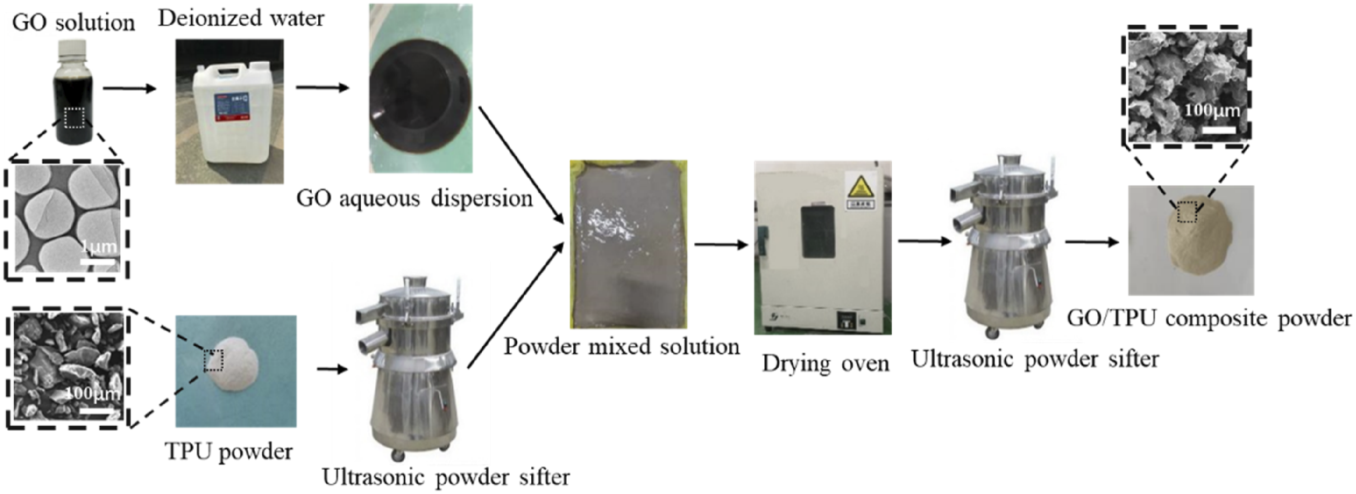
LS Processes
LS processing parameters.
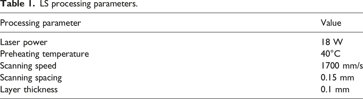
Equipment for LS and schematic diagram of the process.
Post-processing Treatment
After removing the surface particles, the LS-treated item was removed from the LS apparatus and placed in a tube furnace (Shanghai Institute of Fine Mechanics, Chinese Academy of Sciences). To avoid oxidation and combustion during the carbonization process, nitrogen was added to the tubular furnace. The carbonization processing parameters can be configured as follows to improve control of the carbonization process and lower the likelihood of deformation and cracking. After reaching 230°C at a rate of 1°C/min, the temperature was raised gradually to 300°C at a rate of 0.5°C/min while being held for 45 minutes. The temperature was then raised to the desired level (400, 600, 800, or 1000°C) at a rate of 2°C/min for about 1 hour. It was then gradually cooled down to the optimum temperature.
Characterizations
Scanning electron microscope (SEM) FEI Quanta200 was used to observe the microstructure using an electron beam accelerated at a 15 kV voltage (Netherlands FEI Company). The TGA5500 equipment was subjected to a thermogravimetric study (TA Company, USA). Byes3003 universal testing machine (Shanghai Bangyi Precision Measuring Instrument Co., Ltd) was used to assess the bending strength of the LS-processed part, and specimens for the bending test was created using the GB/T9341-2008 plastic bending property test method. Using an RTS-9 four-probe tester, the electrical conductivity of the LS-treated item was assessed at room temperature (Guangzhou Four-Probe Technology Co., Ltd).
Results and Discussion
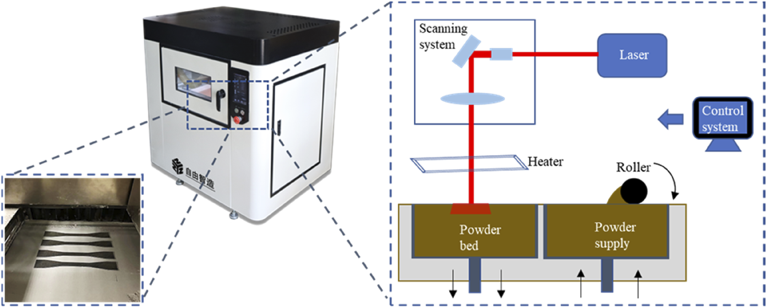
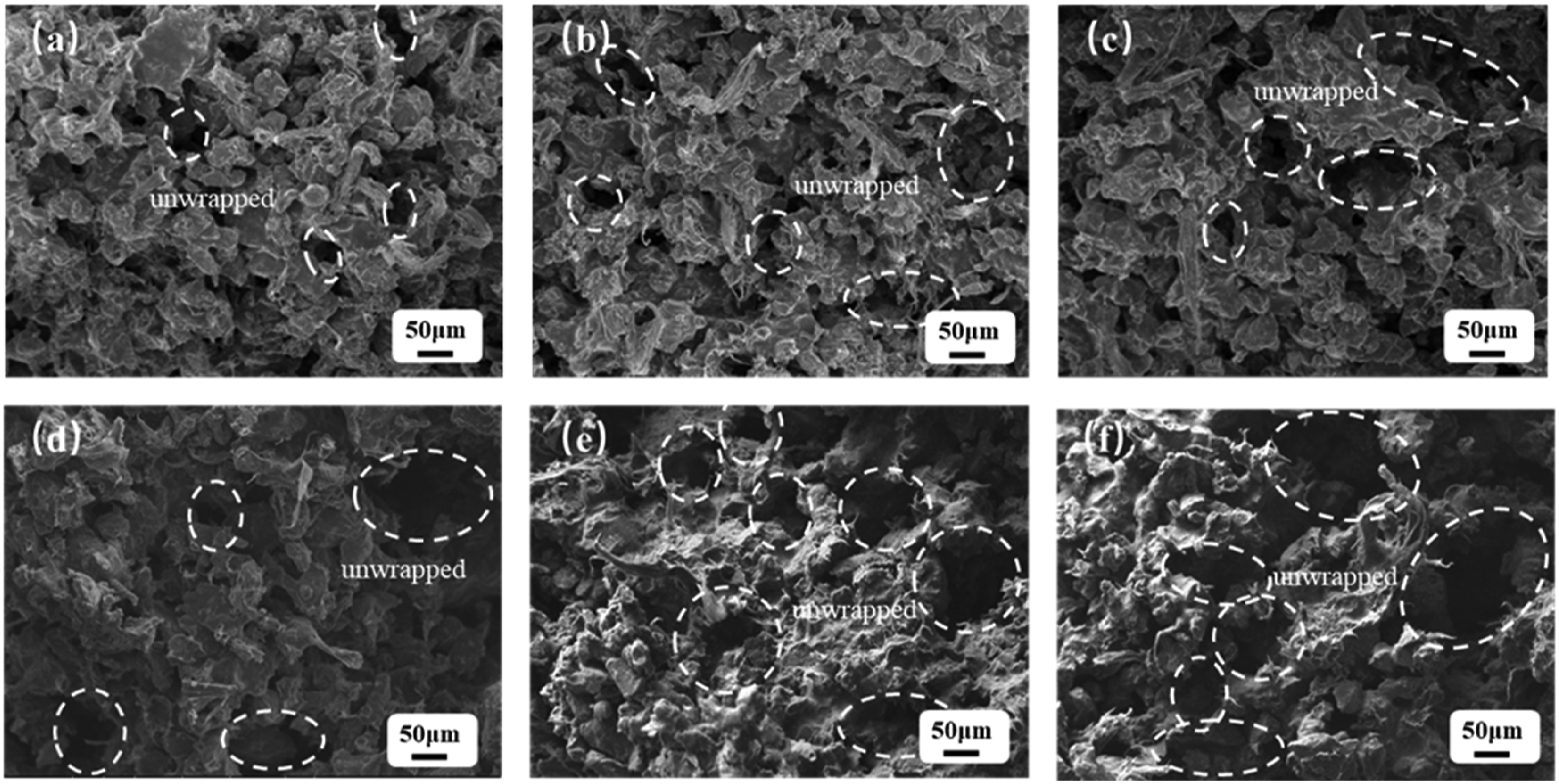
The electrical conductivity of the LS-treated portion is significantly influenced by the GO. The amount of GO in the part will undoubtedly have an impact on how well it forms because TPU must be added for melting and binding the GO. In Figure 2(a), it is shown that the pure TPU section has few visible pores, and several massive sintering necks were produced between the particles, demonstrating strong particle bonds. Figure 2(b)-(d) presented the microscopic morphologies of sintered components of GO/TPU composites with GO contents of 1, 1.5, 2, 2.5, and 3 wt%, respectively. The pores of the sintered portions are substantially larger than those of pure TPU when compared to pure TPU. It could be explained by the fact that more GO cannot be wrapped by the melted TPU particles as the amount of GO continuously increased. Resultantly, from a macroscopic standpoint, the mechanical features of LS-treated parts showed a decreasing trend as the combination of GO and TPU particles weakened. (Figures 3 and 4). Characterization process. Microscopic morphologies of GO/TPU parts with different GO contents: (a) Pure TPU (b) GO content of 1 wt% (c) GO content of 1.5 wt% (d) GO content of 2 wt% (e) GO content of 2.5 wt% (f) GO content of 3.5 wt%.
The effects of GO content on the bending ability and density of LS-treated parts are shown in Figure 5. The bending strength of the sintered part of the GO/TPU composite steadily decreased as the GO percentage raised in comparison to pure TPU. The bending strength of the LS treated portion decreased by 1.14 MPa as the GO content was increased from 1 wt% to 1.5 wt%. Combining SEM observation, it was shown that the viscous flow of TPU particles might be significantly impacted when the content of GO was gradually raised while being heated by a laser. Fewer sintered necks formed as a result of a weakening of the particle bonding effect. Consequently, the sintered portion had greater porosity with the increase in GO content. Therefore, with the greater porosity and content, bending strength and density were decreased.
24
The variations in the bending strength and density with different GO contents.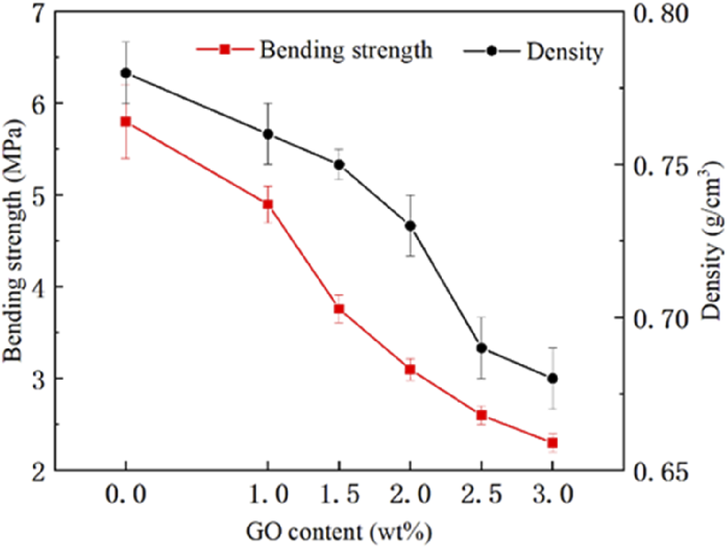
The TG curves of sintered parts with GO contents of 0, 1, 2, and 3 wt% were shown in Figure 6. The TGA variation of pure TPU was essentially the same as that of GO/TPU composites with various GO concentrations. These situations were attained when the temperature was lower than 260°C. Naturally, 293°C was the temperature at which pure TPU pyrolysis. In contrast, GO/TPU composites’ pyrolysis temperature was in the range of 303 °C–308°C, up to 15°C higher than that of pure TPU. It highlighted how adding GO could increase the thermal stability of TPU material. Since graphene’s high thermal conductivity made it easier for heat to dissipate inside such composites. TG curves of LS processed parts of GO/TPU composites with different GO contents.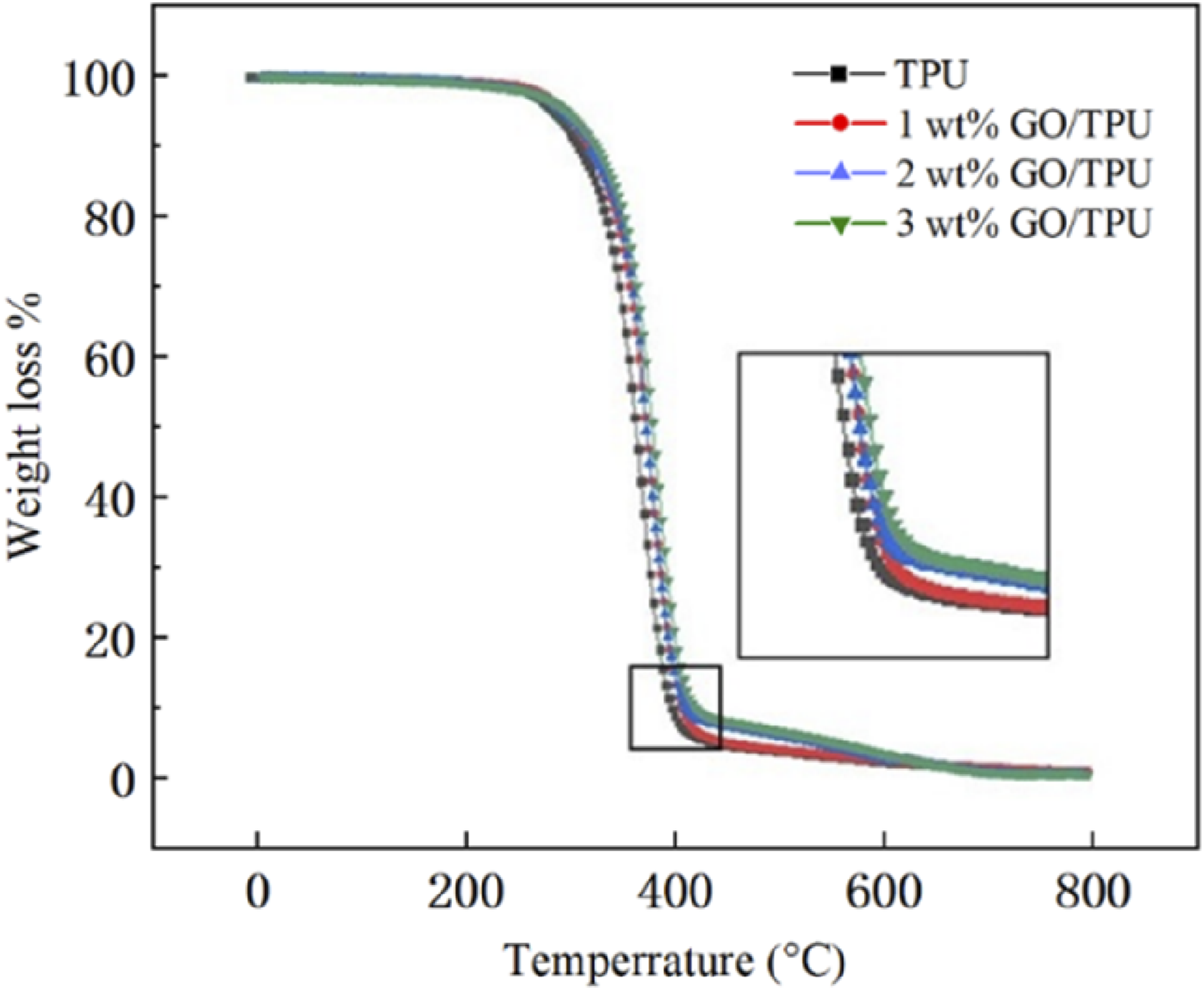
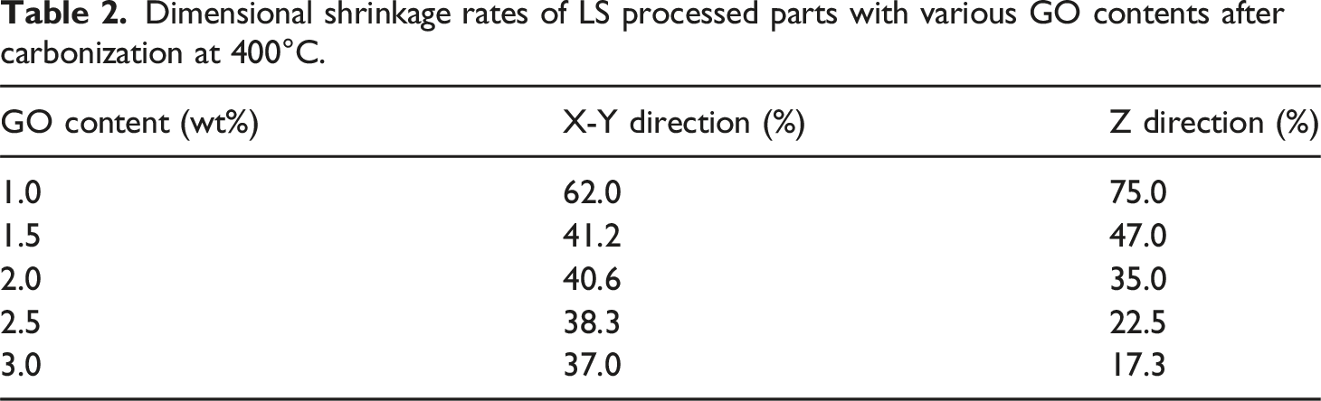
To increase electrical conductivity, carbonization treatment was used for the LS-processed component. The morphologies of LS-treated pieces with various GO contents are shown in Figure 7 following heating at 400°C in a vacuum tubular furnace. The geometry of a sintered object could be preserved as GO content increased, but volume loss could also be seen. Table 2 provides an overview of the X-Y and Z-direction shrinkage rates of sintered parts with various GO concentrations. According to Table 2, the dimensional shrinkage was significantly reduced when the GO content was raised from 1 wt% to 1.5 wt%, with a decrease of 20.8% in the X-Y direction and 28% in the Z direction. With the constant rise in GO content, the dimensional shrinkage was further reduced, although the pace of decline was noticeably slowed. The dimensional shrinkage was only reduced by 1.3% and 5.2% in the X-Y direction and Z-direction, respectively when the GO content was raised from 2.5 wt% to 3 wt%. It should be highlighted that the TPU has low carbonation and was not heat resistant.25–28 The TPU material was broken down into tiny molecular pieces during the carbonation treatment at high temperatures. This high temperature subsequently allowed for easy volatilization. As a result, the TPU particles in Figure 7(b) cannot be seen, leaving the flake-like RGO to serve as the major supporting structure. The rapid gas escape was caused by the pyrolysis of TPU during the carbonation treatment at high temperatures, as illustrated in Figure 7(c). It also encouraged the development of porous structures inside. Carbonization of LS processed parts and the corresponding SEM images:(a) Morphologies of LS processed parts with different GO contents after carbonization at 400°C; (b) SEM image of LS processed part with the GO content of 2 wt% (×1000) after carbonization at 400°C; (c) SEM image of LS processed part with the GO content of 2 wt% (×2000) after carbonization at 400°C. Dimensional shrinkage rates of LS processed parts with various GO contents after carbonization at 400°C.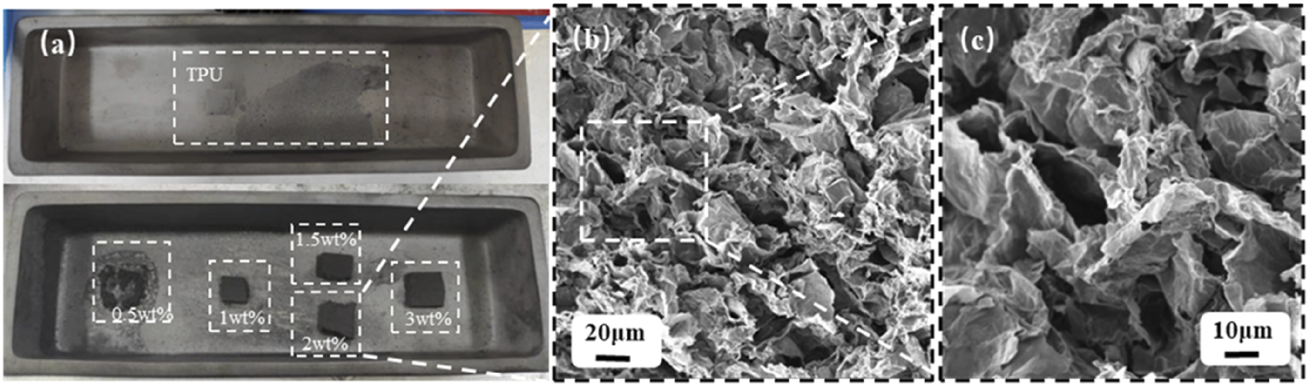
The surface electrical resistivity of LS-treated parts with various GO concentrations following carbonization treatment is shown in Figure 8. The surface electrical resistance of sintered parts following carbonization treatment at a temperature of 800°C was noticeably reduced with the increase of GO concentration when the GO level was below 2.5 wt%. The part’s RGO content and the tightness of the conductive network skeleton inside determined its electrical conductivity, hence increasing the GO content can efficiently boost the electrical conductivity of LS-processed parts.
29
The electrical resistivity, on the other hand, didn’t change significantly when the GO content exceeded 2.5 wt%. When the GO content was high a peculiar phenomenon of dimensional contraction along with density analysis was observed. High GO content also demonstrated flake-like RGO layers of the final carbonized part that could be agglomerated.30–32 The density of the as-built conductive system was no longer noticeably augmented. The conductive contrivance led by the formation of RGO was produced so that the electrical conductivity was no longer increased with the GO content. (a) Surface electrical resistivity of carbonized parts with different GO contents after carbonization at 800°C (b) Surface electrical resistivity of carbonized parts (GO content of 2.5 wt%) at various carbonization temperatures.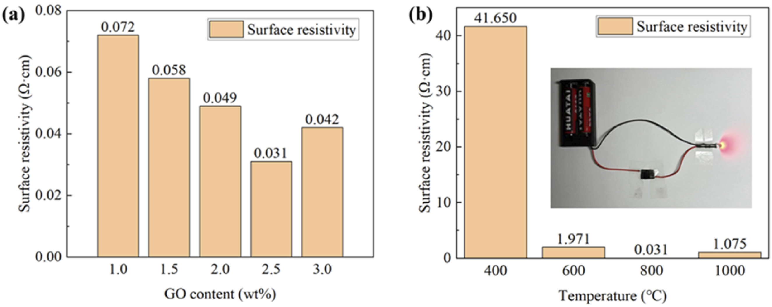
Meanwhile, the carbonation factors influenced the electrical conductivity of LS-processed parts. The surface electrical resistivity consequences of the carbonized part with a GO content of 2.5 wt% at varying temperatures are shown in Figure 8(b). The electrical resistivity of carbonized parts dropped as the temperature rose from 400°C to 600°C, while electrical conductivity dramatically increased. When the temperature reached 800°C, the residual oxygen-containing functional groups on the flake-like RGO could be eliminated, 33 resulting in the carbonized part exhibiting excellent electrical conductivity. Furthermore, such a component could be linked in series in the circuit, and the current could then pass through this component to light up the LED. However, incredibly high temperatures had the contrary effect. Large bubbles appeared on the material surface were observed due to the extremely high temperature of the carbonization process at 1000°C. The appearance of bubbles could be related to the high magnitude of destruction to the internal flake-like RGO assembly. A significant reduction in the electrical conductivity of the composite material was also associated with carbonization.
Conclusions
In this study, for the production of the GO/TPU composite part, the solution blending method was used to combine TPU and GO with a content of less than 3 wt%. To produce the conductive part, carbonization treatment was used for the entire LS-treated GO/TPU composite part. Investigating the effects of GO content on the LS-processed composite portion was done methodically. It was proven that as GO content rose, the porosity of the sintered portion increased and the parallel density and bending strength decreased. On the carbonized GO/TPU composite parts, the effects of different GO contents (1, 1.5, 2, 2.5, and 3 wt%) were also discovered. It suggested that the inclusion of GO could lessen the volume shrinkage of LS-processed parts brought on by carbonization treatment. A lower volume shrinking rate might have resulted from higher GO content. The surface electrical resistivity of the carbonized GO/TPU composite part was noticeably lowered with the increase in GO content when the GO content was less than 2.5 wt%. The electrical conductivity did not alter much while the GO level was maintained between 2.5 and 3 wt%. With the rise in carbonization temperature, the TPU polymer particles were gradually broken down. Primarily microstructure was made up of RGO flake-like particles. The circuit rate of such carbonized portion with GO content decreased as the carbonization temperature approached 800°C. The circuit rate determined was 0.031 Ω ·cm for a such carbonized part with a GO content of 2.5 wt %. This work has effectively demonstrated the viability of using GO/TPU composite material as LS material. After carbonization, it was possible to produce a GO/TPU composite part with outstanding electrical conductivity. This discovery might serve as a guide for DLWc and other technology-based manufacturers of innovative flexible modules. Furthermore, for further research in the near future, the combination of the LS technique and the carbonization process can achieve the simultaneous printing and carbonization of an electrically conductive channel to create flexible conductive elements that can be customized.
Footnotes
Author Contributions
D.M.: Conceptualization, Y.G. and J.L.; methodology, D.M. and Z.Y.; investigation, Y.G.; data curation, Z.Y.; writing—original draft preparation, D.M.; writing—review and editing, Y.G.; visualization, D.M., Z.Y. and Y.G.; supervision, J.L and Y.G.; project administration, Y.G. All authors have read and agreed to the published version of the manuscript.
Declaration of conflicting interests
The author(s) declared no potential conflicts of interest with respect to the research, authorship, and/or publication of this article.
Funding
The author(s) disclosed receipt of the following financial support for the research, authorship, and/or publication of this article: Supported by Opening Project of the Key Laboratory of Advanced Manufacturing and Intelligent Technology (Ministry of Education), Harbin University of Science and Technology (KFKT202410)
Data Availability Statement
The authors declare that the data supporting the findings of this study are available within the article. Complementary data relevant for the present study are available from the corresponding author upon reasonable request.