
Abstract
A polyester fiber-reinforced thermoplastic composite pipe (FRTP) utilized for high-pressure water transportation experienced perforation leakage and bulging rupture of the outer protective layer after 6 months of service. The study was conducted by physical and chemical properties test, thermal analysis, mechanical analysis, pressure performance analysis, and morphology analysis. The failure primarily due to a crack defect on the inner surface of the cross-linked polyethylene (PEX) of this pipe, which allowed it to pass the pressure test but led to failure after a period of operation. Under the continuous action of high pressure, the crack expands and the lining layer is perforated, forming a leakage point through which high-pressure fluid entered the interlayer and accumulated in the outer protective layer of the pipe body. This outer protective layer gradually thinned and the high-pressure fluid at the leakage point pierced through the pipe, forming a perforation failure on the pipe body.
Introduction
Fiber reinforced composites are a class of advanced materials formed by high-strength fibers embedded in matrix materials ( such as polymers, metals or ceramics ). The core idea is to combine the advantages of both ( such as the high strength of the fiber and the toughness of the matrix ) through the synergistic effect of the fiber and the matrix to achieve better comprehensive performance than a single material. Fiber-reinforced composites are shifting from “replacing traditional materials“ to “achieving performance that traditional materials cannot match”, especially in the context of carbon neutrality. Its lightweight advantages promote innovation in traditional energy, transportation and other fields. The fiber reinforced thermoplastic composite pipe (FRTP) is a non-metallic pipe increasingly used in the surface production systems of western oilfields, effectively solving the corrosion problem of gathering pipelines. In recent years, the use of FRTP pipes in oilfields has been increasing steadily. An FRTP pipe consists of a thermoplastic pipe as the matrix, reinforced by organic fibers (such as aramid or polyester fibers) in reinforcement bands, covered with a thermoplastic protective layer. A typical organic fiber reinforced thermoplastic composite pipe has a three-layer structure, as shown in Figure 1. As the quantity of FRTP pipe used and the expansion of application conditions have increased, the problems associated with FRTP pipes in field applications have also increased.1–5 Qi
1
sdudied a crack failure of polyvinylidene fluoride (PVDF)-lined RTP pipe used in acidic gas fields. Kong
2
researched burst failures in RTPs because of the damage to sealing rings led to the leakage of conveying medium in the joint. Li,
3
Zhang,
4
and Ding
5
studied failures of steel-reinforced thermoplastic pipes (SRTPs) due to defects in the properties of resin materials, leading to environmental stress cracking (ESC). Appearance and structure of the FRTP.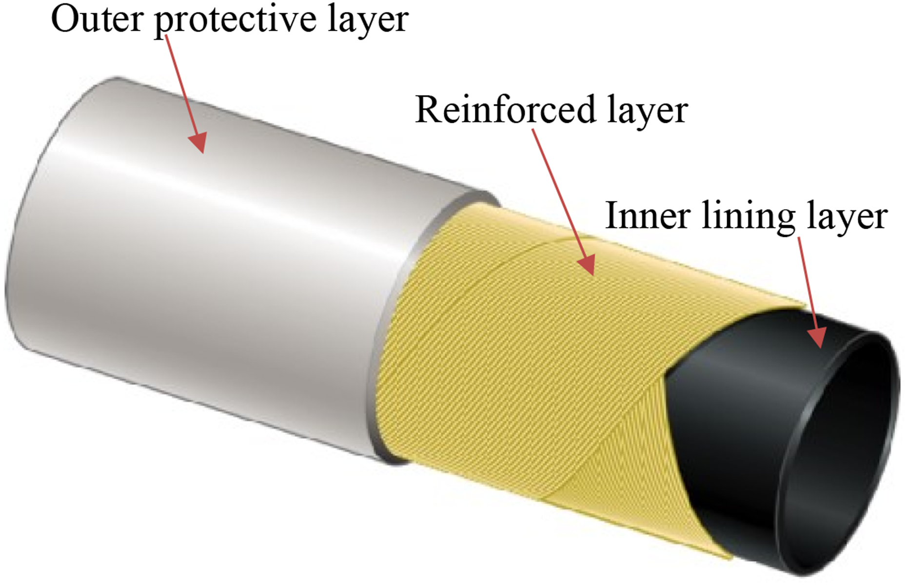
Thi D. Le 6 focuses on the design of a Reinforced Thermoplastic Pipeline (RTP), made of High-density polyethylene (HDPE) inner pipe, reinforced by glass fiber wrapping (GFRP), and inserted into an outer HDPE pipe, under internal pressure. Zahiraniza Mustaffa 7 attempts to highlight the response of RTP imposed to crack failures using hydrostatic burst test and validated with numerical simulations under various internal pressures. Malik Abdul Karim 8 evaluate the key mechanical properties of BRTPs, including hoop tensile strength, axial tensile strength, and parallel plate compression test. M. Elkhodbia 9 presents a comprehensive assessment of the failure of a steel-reinforced flexible thermoplastic composite layered pipe in a sour environment characterized by hydrogen sulfide (H2S) exposure. Reis 10 researched influence of aging on the failure pressure of glass fiber reinforced polymer (GFRP) pipes used in the oil industry.
A large body of literature and numerous scholars’ have demonstrated the non-metallic pipes failure because of service working conditions, such as temperature, pressure, and medium. Liu
11
and Kuang
12
used numerical simulations of steel-reinforced flexible pipes (SRFPs) and steel strip reinforced flexible pipes (SSRFPs) under internal pressure. Shi
13
researched steel wire-reinforced thermoplastic pipes subjected to combined internal pressure and bending moments at various temperatures. Some scholars have also studied the mechanical behavior of non-metallic pipes through modeling. Bai,14–18 Li,
19
Zheng,
20
and Yuan
21
investigated the mechanical behavior of metallic strip flexible pipes under various loading conditions. Fatima Majid
22
analyzed failure and damage modeling of high-density polyethylene (HDPE) pipes. As indicated in this study, failures caused by defects in FRTP pipeline materials are less frequently reported. In this study, a high-pressure water injection FRTP pipe failed during operation. The failure manifested as perforation leakage and bulging, as well as rupture of the outer protective layer, which occurred approximately 10 m from the pipe body, as shown in Figures 2(a) and (b). The pipeline is about 2.7 km in length, with the specification RF-S-II-DN50-32 MPa. The transmission medium is produced water from the gas field. The pipeline was completed and put into operation at the end of November 2022. The operating pressure was between nine and 11 MPa, and the pipe burst after 6 months of operation. FRTP pipe failure appearance.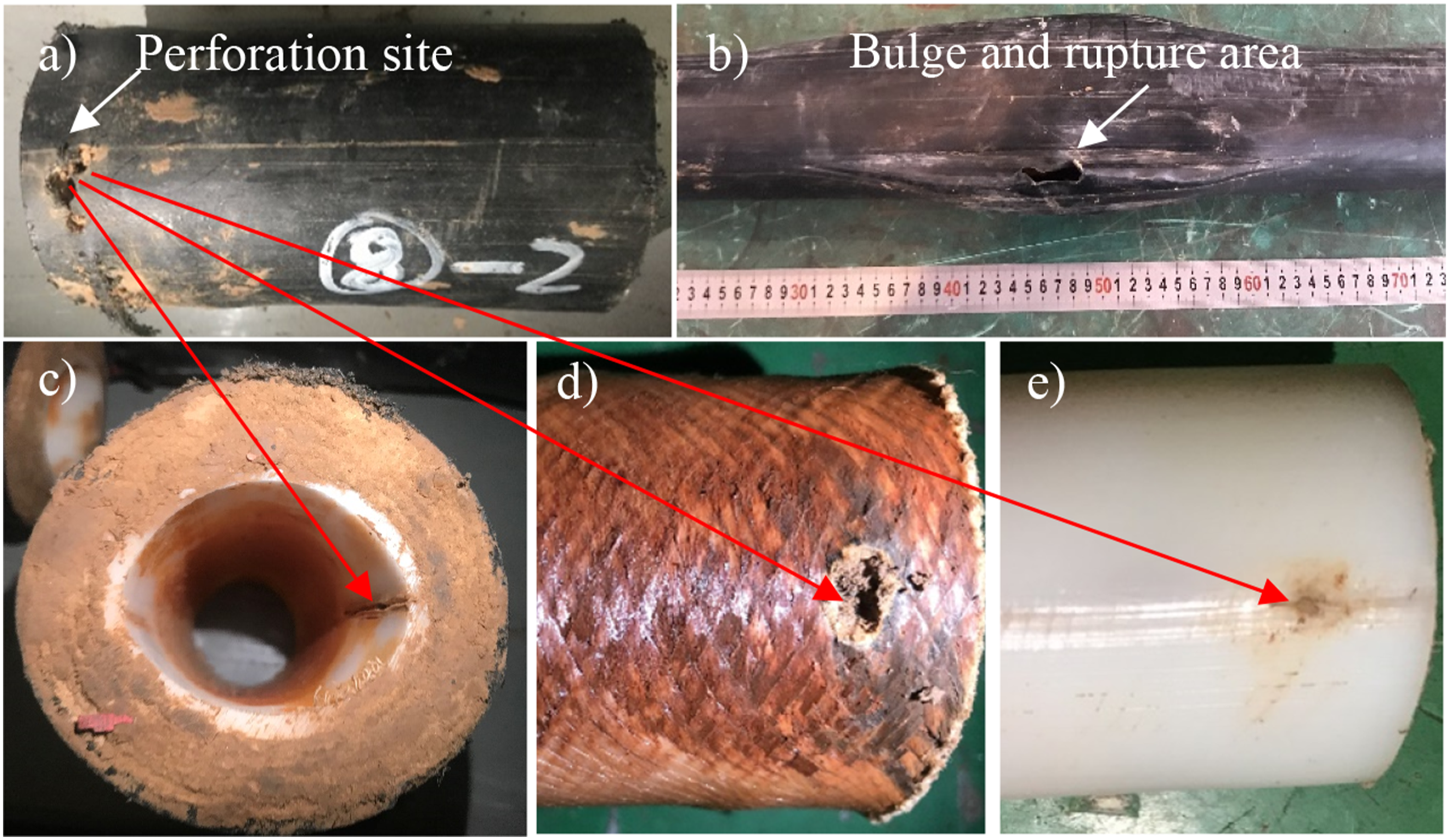
The section of the pipe that experienced leakage failure is depicted in Figure 2(c). This section measures 200 mm in length. In the outer protective layer of the leaking portion, there is a hole approximately 20 mm in size, with corresponding penetrating cracks in the inner liner. These penetrating cracks are also present at the opposite end of the same plane. The shape of the pipe body is elliptical, with the major axis measuring 55.42 mm and the minor axis measuring 46.63 mm. Cracks are distributed at both ends of the elliptical shape. The failed pipe was dissected, and upon peeling off the outer protective layer, it was observed that the reinforcing layer tapered in a ‘horn'-like shape, narrowing from the outside inward, and culminating at a point on the outer surface of the inner lining layer, as shown in Figures 2(d) and (e).
Experimental
To determine the reasons for the perforation, bulge, and rupture of the FRTP pipe, a series of experiments were conducted to thoroughly investigate the causes of the failure. The density of the liner was detected by gas pycnometer method by a densimeter. The XRD-300DL vicat softening temperature (VST) tester was employed to test the VST of the inner pipe. The Nicolet iS50 Spectrometer was used to test the attenuated total reflection fourier transform infrared (FTIR) spectroscopy of inner pipe to study the characteristic functional groups. The degree of crosslinking of the inner liner samples was tested using a heating extraction with xylene. The oxidation induction temperature (OIT) of the inner pipe was determined using a differential scanning calorimeter (DSC) by TA AQ200. The AGS-X10 kN ultra-large stroke testing machine was utilized to test the tensile strength and elongation of the inner pipe, respectively. The compressive cracking stability of the complete pipe section also adopted by the AGS-X10 kN test machine. Besides, a full-size physical pipe hydrostatic pressure and hydraulic blasting test were carried out on a non-metallic pipe hydraulic test system by TGRI-CDJM SY-II. Finally, the morphology of the leakage point and the crack morphology of the lining layer of the failed pipe were systematically observed using an optical microscope (OM) and scanning electron microscope (SEM).
Results and Discussion
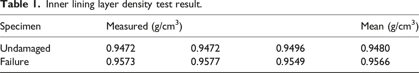
Density of the Inner Lining Layer
Inner lining layer density test result.
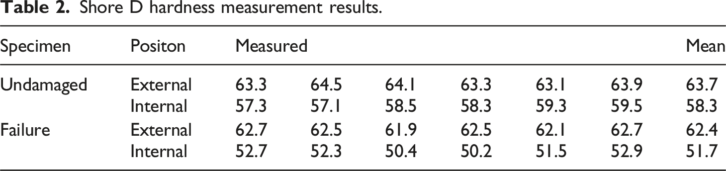
Hardness of the Inner Lining Layer
Shore D hardness measurement results.
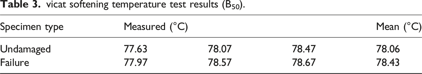
Vicat Softening Temperature
vicat softening temperature test results (B50).
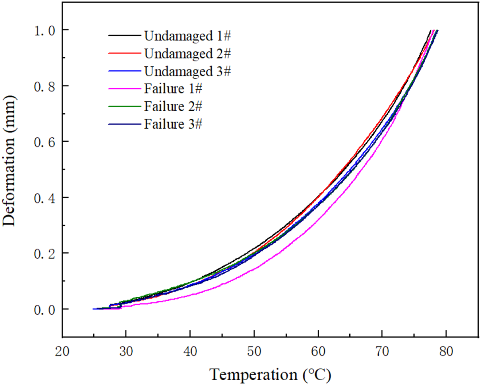
Temperature deformation curve of the inner lining layer.
Infrared Spectrum
To find out the structural composition of the inner lining layer of the undamaged and failed parts, infrared analysis was performed on the undamaged part of the lining, the area near the perforation, and the perforation itself. The infrared (IR) spectra inner lining layer of the RTP (reinforced thermoplastic) pipe specimens test results are depicted in Figure 4. The spectra confirm the lining material is polyethylene, with clear characteristic absorption peaks of the polyethylene. The infrared (IR) spectroscopy results show that the failed samples of the RTP (reinforced thermoplastic) pipe exhibit different absorption peaks at 1072 cm−1, suggesting the presence of impurities or foreign matter at the pipe perforation. ATR-FTIR spectra of the inner lining layer.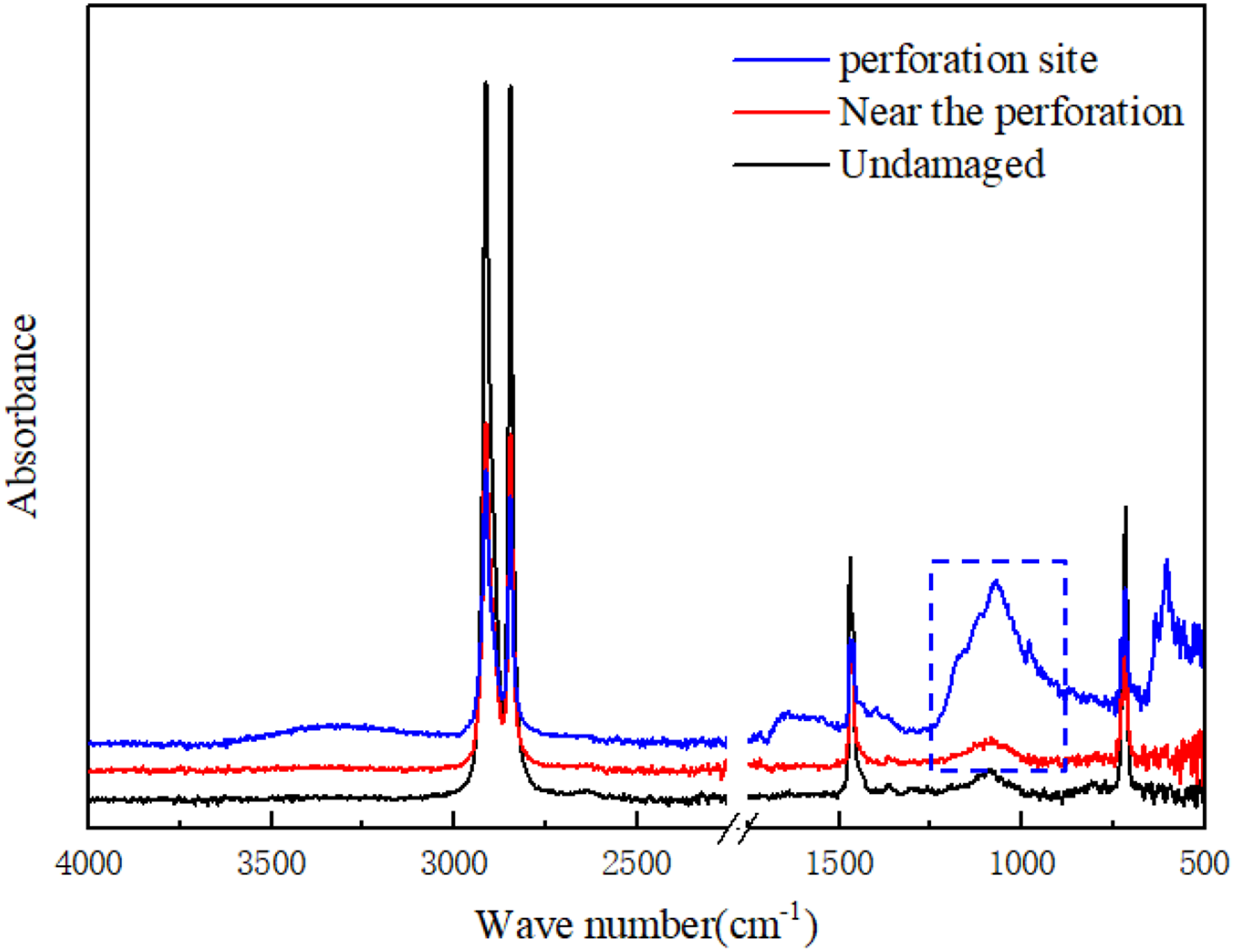
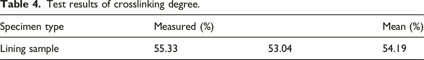
Degree of Crosslinking
Test results of crosslinking degree.
Differential Scanning Calorimeter
Samples were taken from the undamaged and perforated parts of the inner lining layer of the RTP pipe. Differential scanning calorimeter (DSC) was used to figure out the melting point, melting enthalpy, and oxidative induction time (OIT) of the inner lining layer, presented in Figure 5, provide insights into the thermal properties of the RTP pipe’s inner lining layer. The increased melting point and decreased melting enthalpy in the failed part suggest that the resin’s structure may have been altered, potentially due to degradation or the presence of impurities. The lower OIT in the failed part indicates a reduced resistance to oxidative degradation, which could have contributed to the pipe’s failure. The lower thermal degradation capacity in the failed part indicates that the resin was more susceptible to degradation under thermal stress, which could have accelerated the failure process. DSC curves of the specimens of the pipe.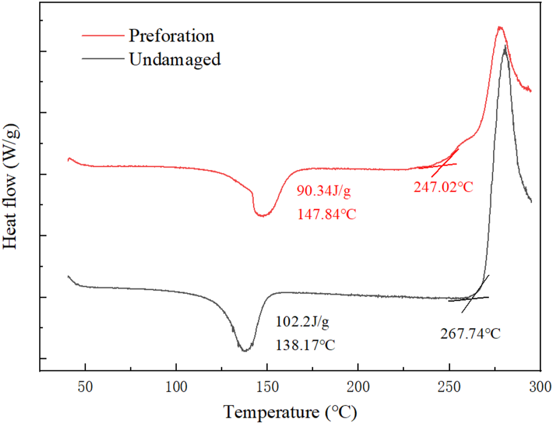
Tensile Strength
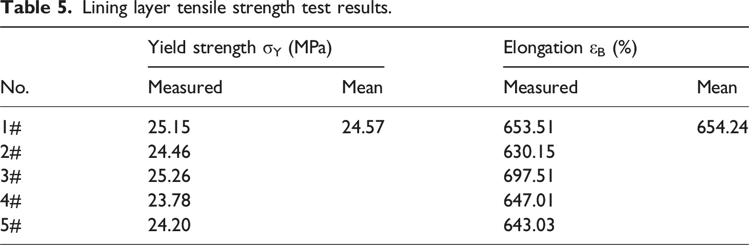
Lining layer tensile strength test results.
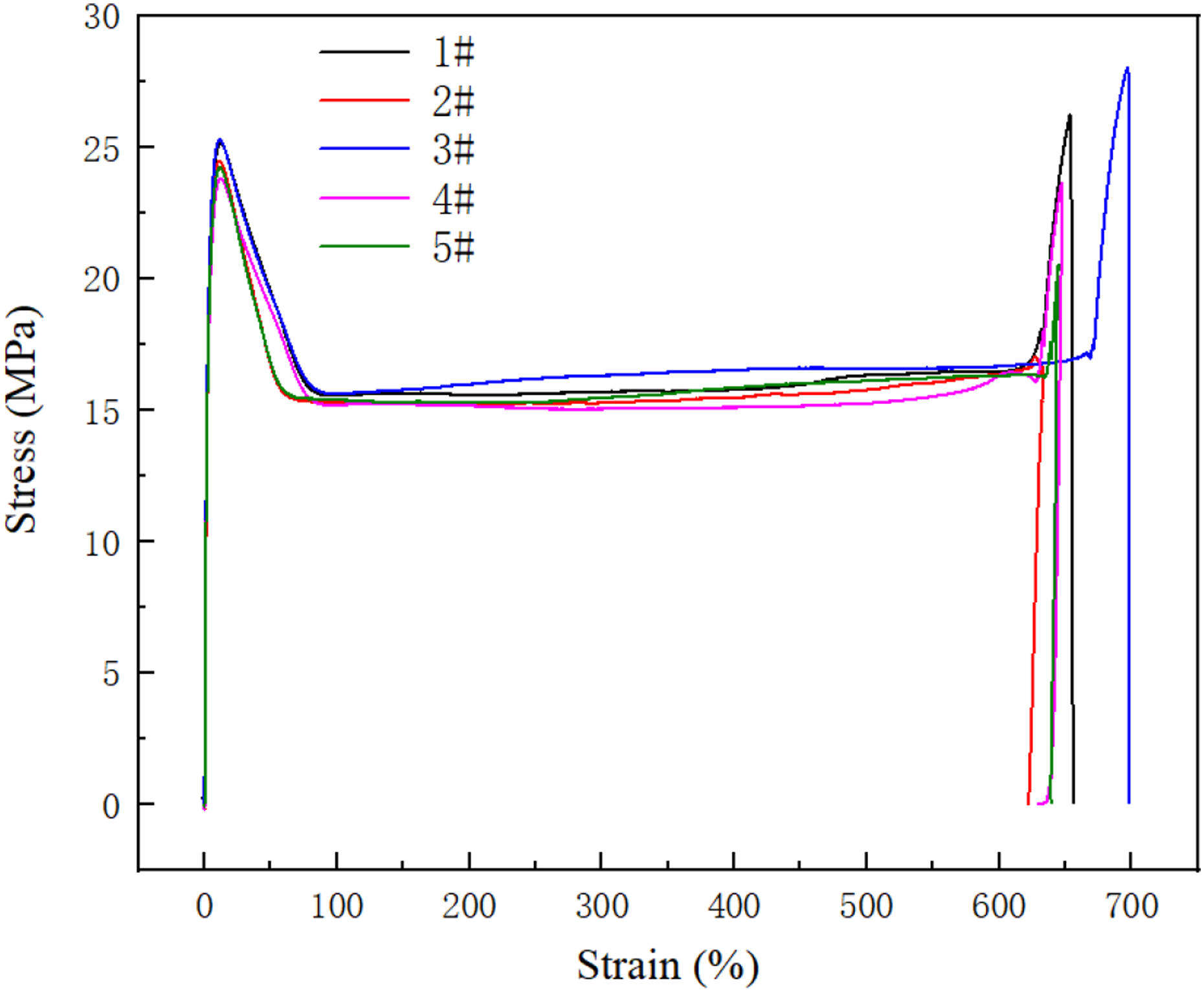
Tensile strength stress-strain curve.
Pressure Performance Analysis
The pressure-bearing performance of the composite pipe, including its ability to withstand external and internal pressures, was analyzed. As illustrated in Figure 7, after the intact sample is compressed to 1/2 of the pipe’s outer diameter in 10∼15 seconds, there are no cracks on the visual sample’s surface, and its compressive cracking stability meets the requirements of SY/T 6662.2-2020. Figure 7 is mainly to verify whether the lining crack is formed by external pressure. The flattening test verifies that even if the inner wall of the pipeline is pressed to fit, the lining does not crack, and the possibility of lining cracking caused by external pressure is excluded. Compression cracking stability test results.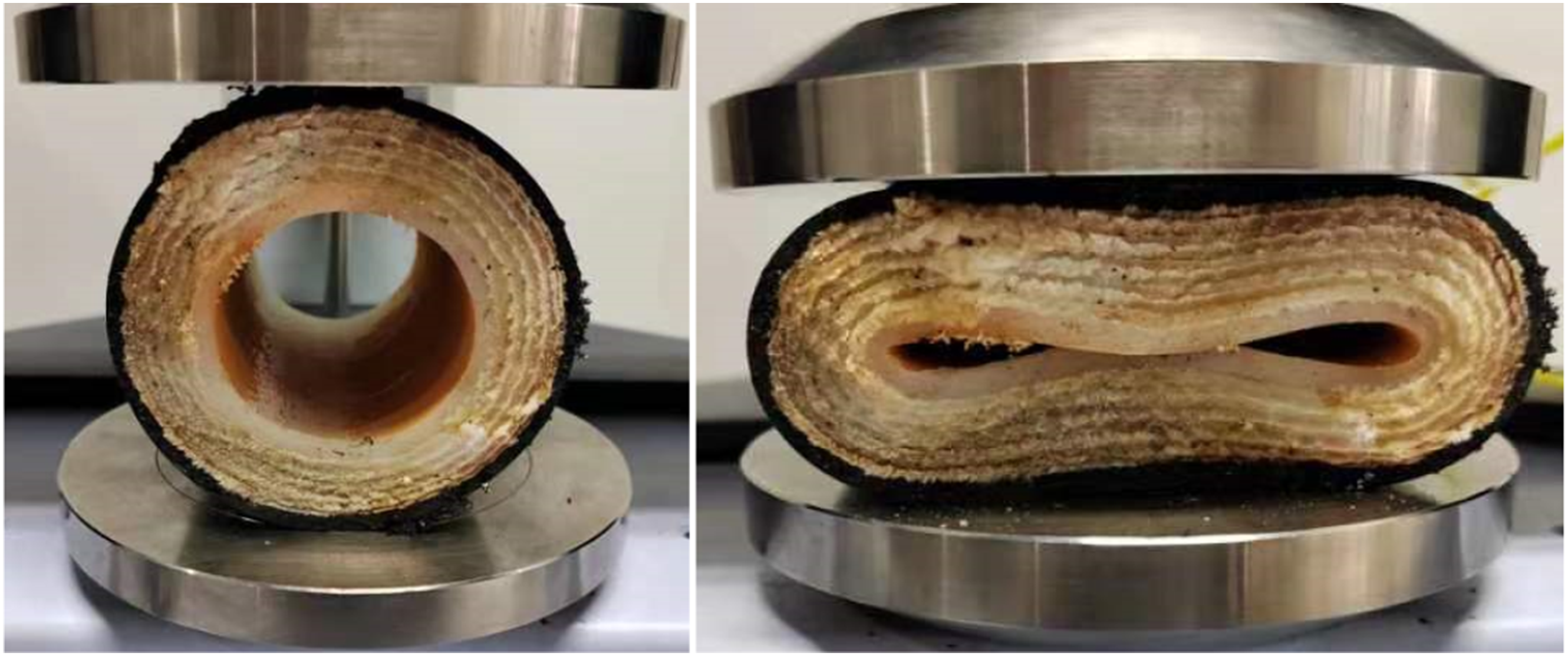
Referring to SY/T 6662.2-2020, the intact sample did not crack or leak under the condition of room temperature and two times the nominal internal pressure for 1 hour. Hydrostatic internal pressure test pressure-time curve is shown in Figure 8. Generally, the short-term hydrostatic test under 2 times nominal pressure is used to test its long-term pressure bearing performance. If it leaks during the test, it shows that its pressure bearing performance does not meet the requirements. Hydrostatic internal pressure test pressure-time curve.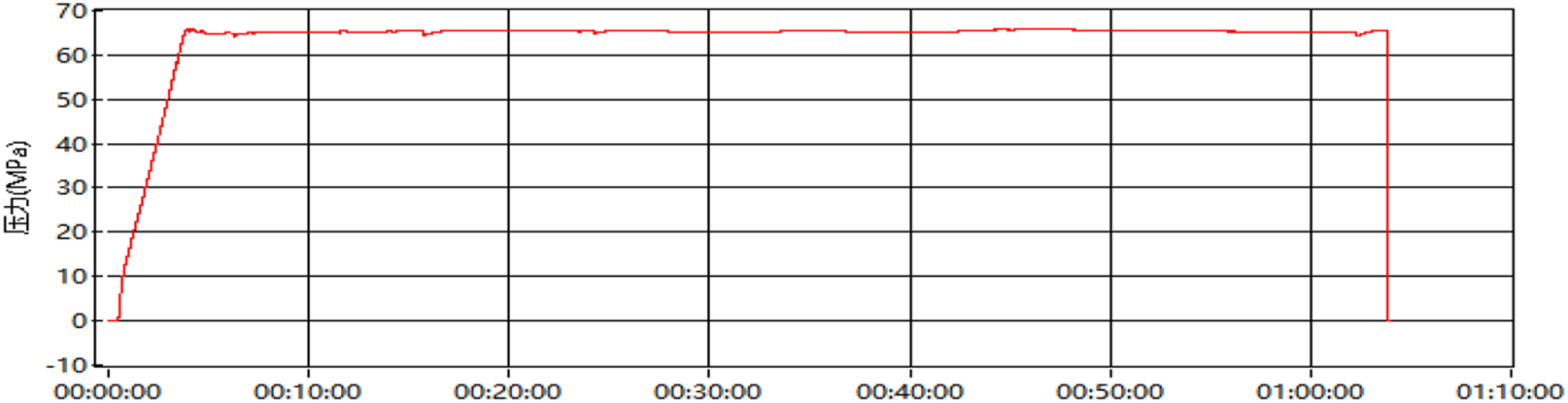
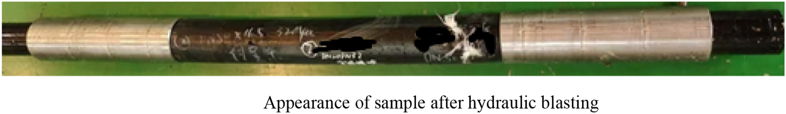
The sample underwent a hydraulic burst test at room temperature. The burst pressure was 100.9 MPa. The pressure curve is present in Figure 9, and the sample after the burst test is present in Figure 10. Before the blasting test, Figure 10 is the intact pipe samples were taken from the adjacent positions of the failed pipeline, mainly to test whether the ultimate pressure bearing capacity reached more than three times the nominal pressure of the pipeline. The burst strength of the samples at room temperature meets the requirement of SY/T 6662.2-2020 that the burst strength must be higher to 3 times of the nominal pressure. Pressure-time diagram of hydraulic blasting. Appearance of sample after hydraulic blasting.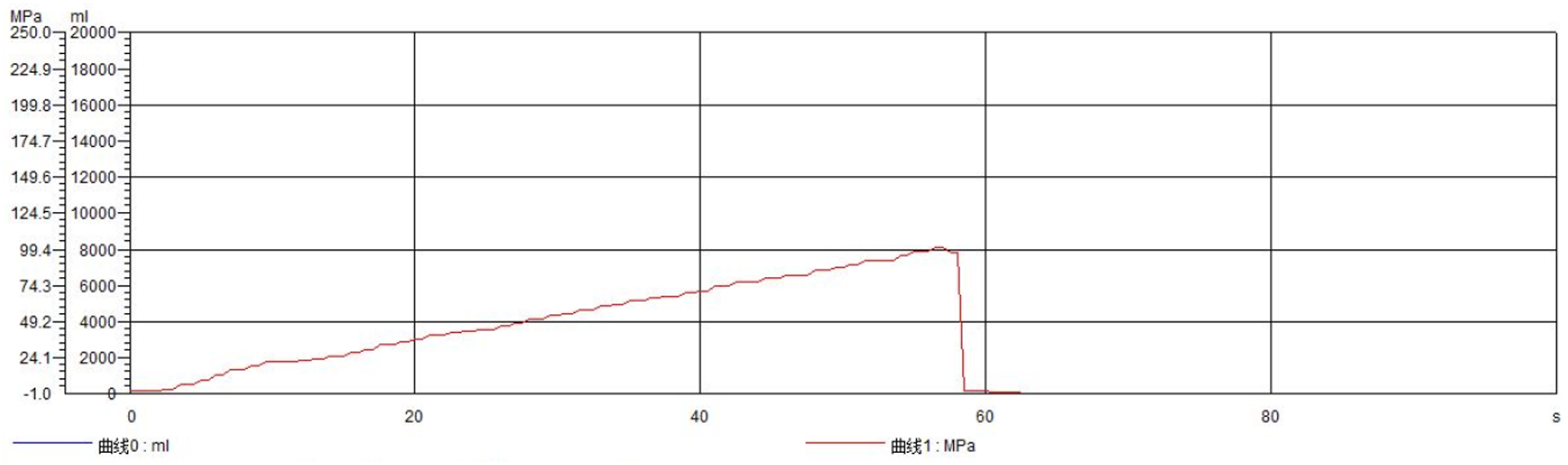
Morphology Analysis of the Leakage
The inner surface at the puncture point displays a penetrating crack, as depicted in Figure 11(a). The leakage point and crack morphology of the lining layer of the failed section are exhibited in Figure 11(b). The leakage point in the lining layer originated from the leakage of the high-pressure fluid, creating a hole roughly 3 mm in diameter. On both sides of this hole, along the longitudinal axis of the pipe body, there are penetrating extension cracks, and there is a non-penetrating crack parallel to the upper end of the penetrating crack. Figure 11(c) and (d) presents a close-up view of the puncture point and the penetrating crack. The lining at the puncture point is torn, displaying ductile cracking characteristics, while the penetrating crack appears smoother and exhibits brittle cracking characteristics. Figure 11(e) and (d) shows the sample fractured along the crack, with the crack surfaces Figure 11(c) andbeing overall flat. The brittle cracking near the inner wall constitutes approximately 2/3 of the wall thickness, and the ductile cracking near the outer wall accounts for about 1/3 of the wall thickness, confirming that the inner lining layer predominantly experienced brittle cracking. The inner surface of the lining layer at the failure site.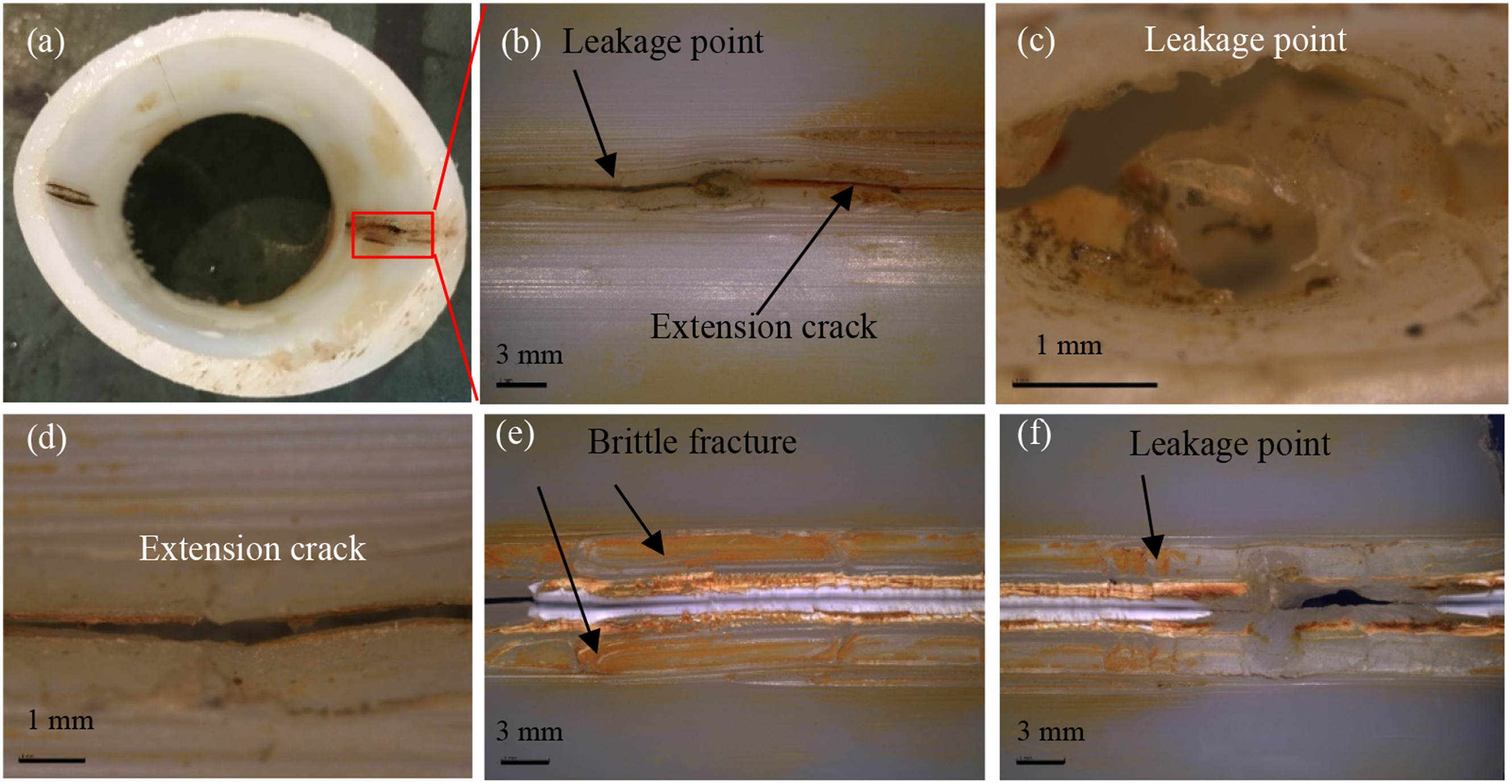
Figure 12(a) and (b) are the electron microscope morphology of the resin at the perforation site, which has the characteristics of ductile cracking morphology. Figure 12(c) and (d) are the electron microscope morphology of the resin at the crack section, which has the characteristics of brittle cracking morphology. The SEM of the lining layer at the failure site.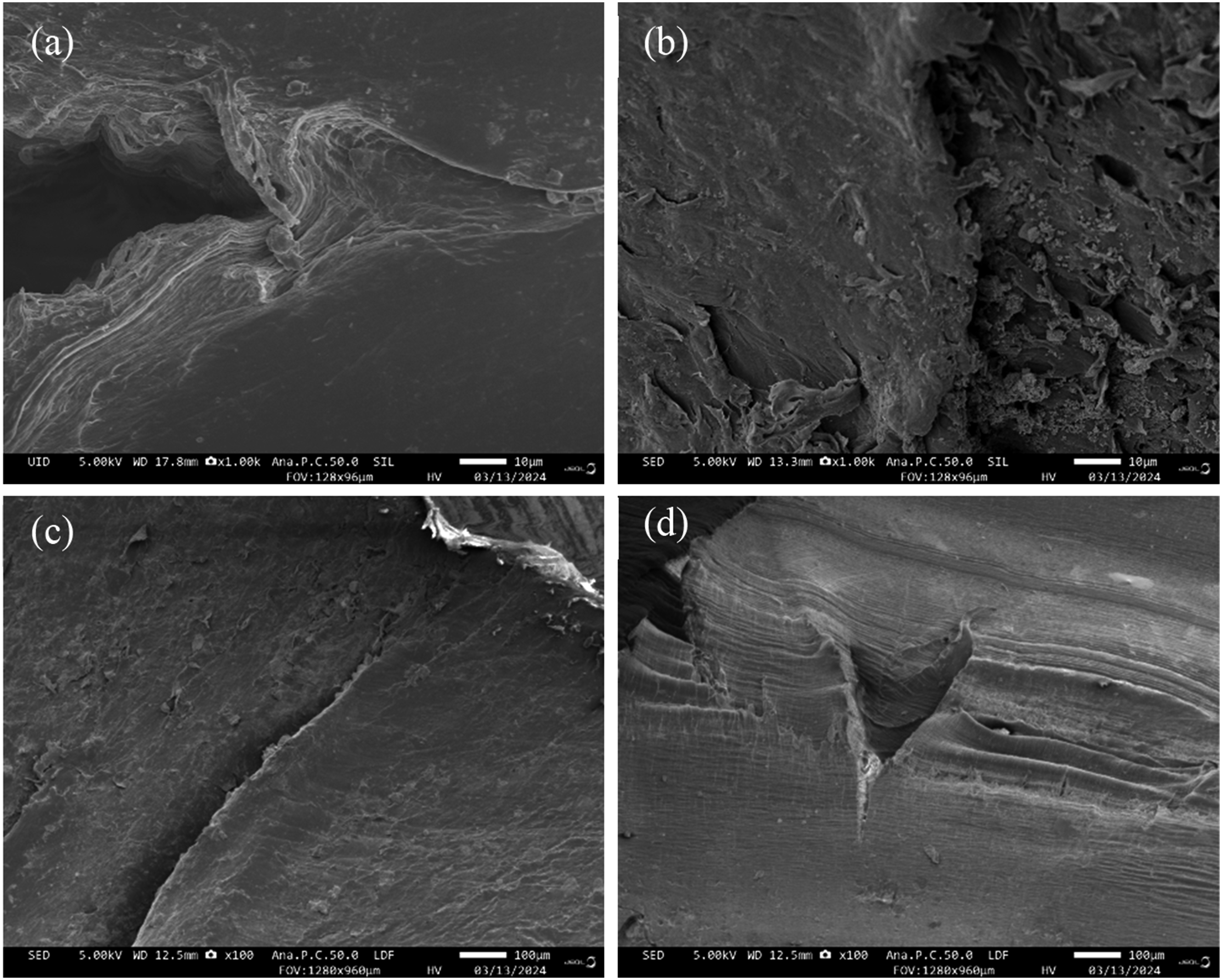
As shown in Figure 13(a) and (b), the non-penetrating crack and the end of the crack are locally amplified, and the crack extension direction is consistent with the direction of the lining extrusion line and parallel to the other extrusion lines. Figure 13(c) and (d) shows a non-penetrating crack with a puncture at the other end of the pipe body (see Figure 2), which is consistent with the previously mentioned non-penetrating crack. The crack is present on the extrusion line, inner surface of the fracture exhibits characteristics of brittle cracking. Near the outer surface, there are characteristics of both ductile and brittle cracking, but it is predominantly brittle. The morphology of the lining layer at the unpenetrated crack.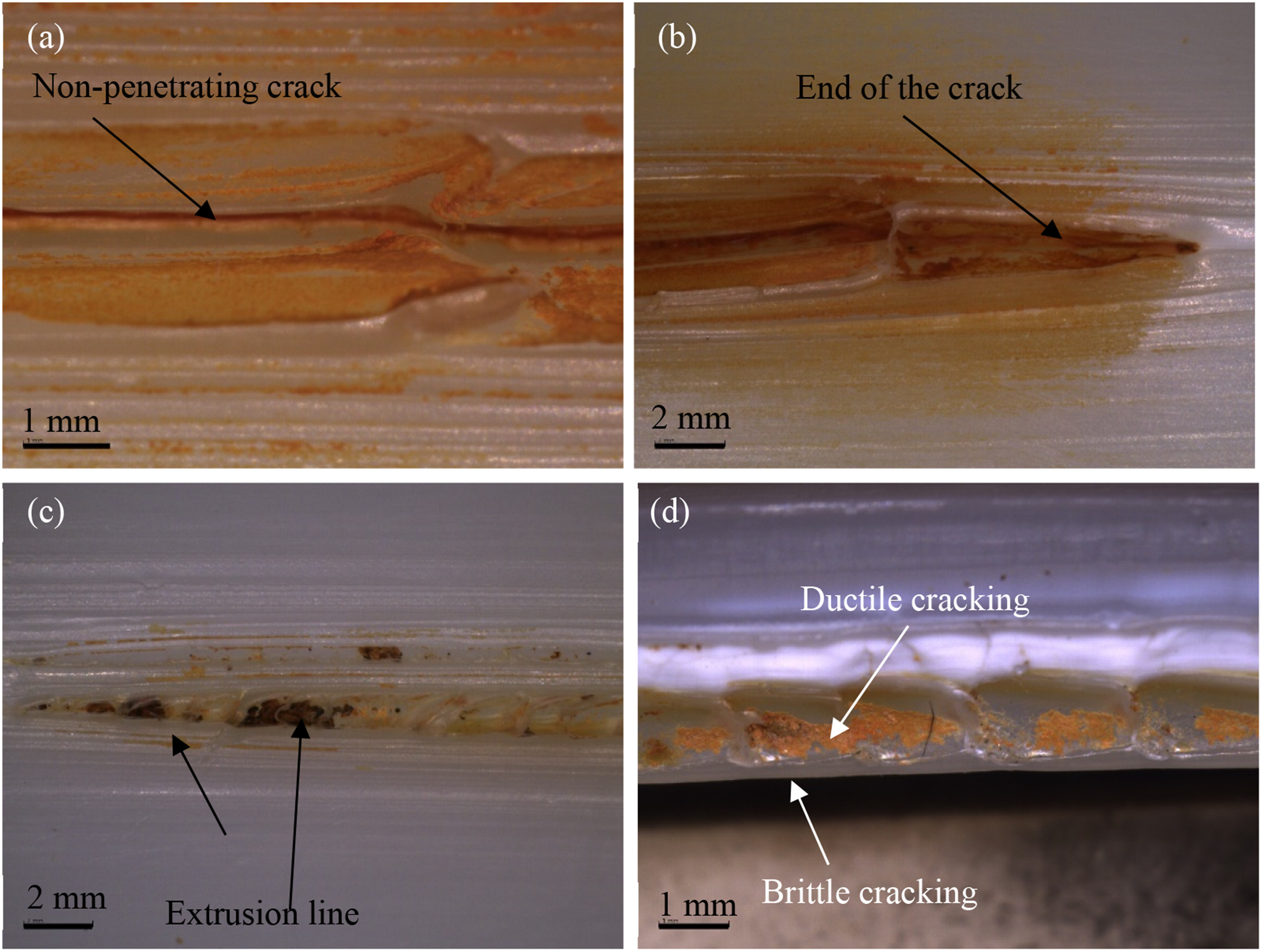
The resin fracture and crack tip of the unpenetrated crack are shown in Figure 14(a) and (b) respectively. The fracture surface is flat and shows the characteristics of transgranular joint fracture. The SEM of the lining layer at the unpenetrated crack.
Analysis of the Bulging Rupture
The bulged area of the outer protective layer extends approximately 500 mm and has thinned and ruptured along the circumferential uplift of the pipe body, as shown in Figure 15. When the bulging pipe was dissected, it was discovered that the reinforcing layer fibers exhibited signs of sewage immersion in the area of the bulge and its left end, while no such signs were found at the right end. The inner and outer surfaces of the lining layer showed no signs of bulging or breakage, and the structure remained intact, as depicted in Figure 16. Appearance morphology of the bulge area of the pipe. Appearance morphology of the bulge area of the pipe after dissection.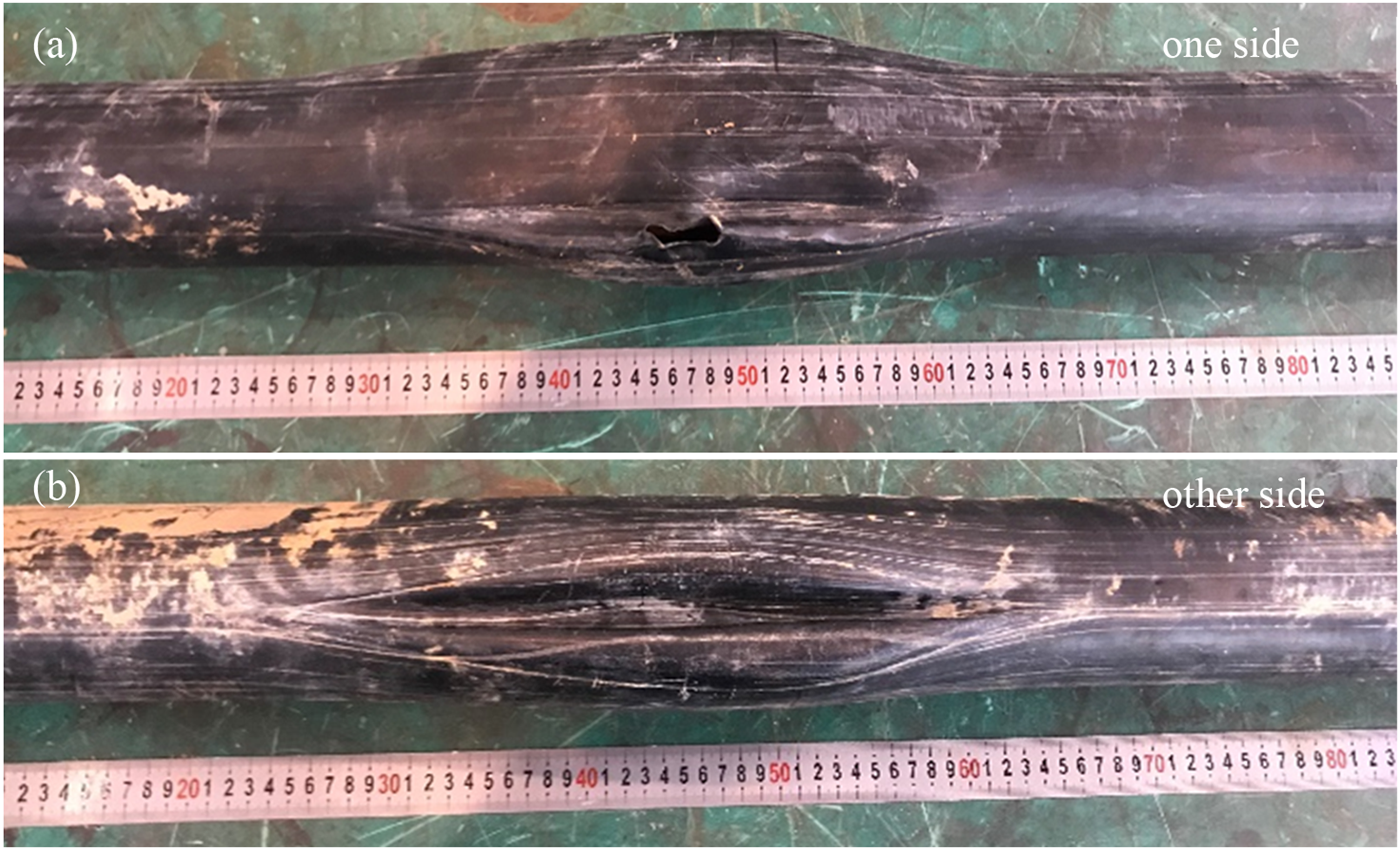
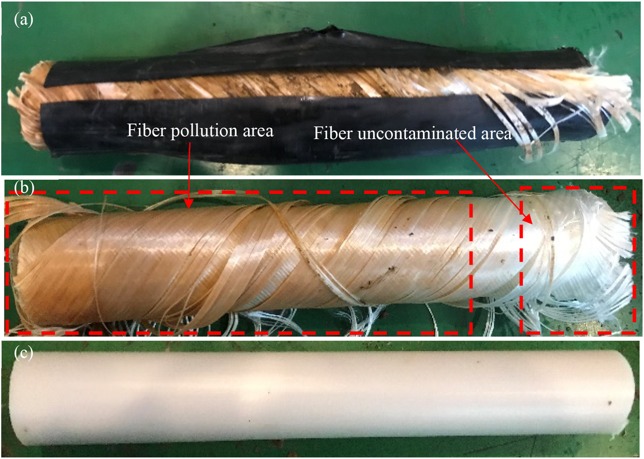
As illustrated in Figure 17, the pipe sections adjacent to the longitudinal extension direction of the bulge area were dissected, revealing traces of sewage immersion in the fibers of the left pipe section and no traces on the right side. According to feedback from the site, the location more than 10 m to the left of the bulge area is the failed pipe section shown in Figure 2. It is surmised that after the sewage seeped out from the lining crack of the failed section, it entered the reinforcing layer. The bulge formed in the area where the outer protective layer was relatively weak, more than 10 m to the right of the leakage site. Here, the outer protective layer became thinned and ruptured, and the fluid ceased to further penetrate to the right within the interlayer. The appearance of the pipe sections on both sides of the bulge area after dissection.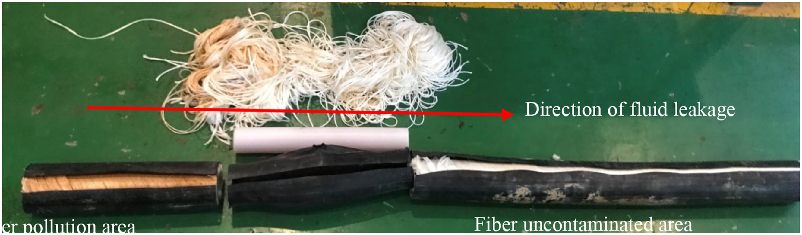
Root Cause Analysis
Material Analysis
The liner density of the samples from both the intact and failed pipe sections of the produced water reinjection flexible composite pipe meets the requirements of GB/T 15,558.1-2015. The results of infrared spectroscopy and the crosslinking degree test confirm that the lining material is cross-linked polyethylene. The analysis results of the tensile strength of the lining layer indicate the lining material remain stable. The test outcomes for compressive cracking stability, hydrostatic pressure, and burst strength of the pipe body demonstrate that the performance of the pipe body under external and internal pressure complies with the standard for flexible composite high-pressure conveying pipe RF-S-II-DN50-32 MPa. The results of the Shore hardness analysis at the failure site indicate that the hardness at the puncture or crack site is about 11% lower than at the intact position, and the failure site is relatively soft, making it more likely to form longitudinal creases after the pipe body is compressed. The analysis of the oxidation induction temperature shows that the antioxidant degradation capability of the lining material in the failed section has a lower quality than that in the intact section, making it a weak point in the lining.
Failure Cause Analysis
Based on the feedback from the site, the pipeline underwent a pressure test before commissioning, maintaining a stable pressure of 40 MPa for 4 hours without any pressure drop. The tightness test pressure remained stable at 32 MPa for 24 hours, also without any pressure drop, indicating that the pre-commissioning pressure test met the design requirements. The pipeline’s transmission medium is produced water from the gas field, with the transmission temperature being room temperature, and the maximum operating pressure is 15 MPa. The potential causes of pipe body failure due to swelling, over-temperature, or over-pressure operation have been ruled out.
Morphological analysis results reveal that regular holes have formed on the pipe body, expanding gradually from the inside out. The outer protective layer has holes with an opening diameter of 20 mm, with a corresponding focus in the lining layer of a 3 mm pinhole. The perforation in the pipe body is trumpet-shaped overall, suggesting that it was formed by high-pressure fluid breaching the lining layer. Adjacent to the leakage point in the inner lining layer are penetrating cracks, with unpenetrated cracks found along the extension line and parallel to the penetrating cracks. The end of the unpenetrated crack aligns with the extrusion line on the inner lining layer’s inner surface. The cracks are primarily brittle, with no signs of fusion. These findings indicate that the lining layer developed longitudinal unfused defects along the extrusion line during the extrusion process. Results from material analysis also indicate that the oxidation induction temperature and hardness at this part are lower than in the normal pipe body. Therefore, the unfused defect in the inner liner is identified as the primary cause of leakage and perforation in the flexible composite pipe after a period of field testing and operation.
The anatomical analysis of the ballooned section of the outer protective layer (Figure 17) shows that the lining within the ballooned region is intact. The failure pipe section shown in Figure 2 is approximately 10 m to the left of this ballooned region. It is inferred that sewage leaking from the lining crack of the failed section entered the reinforcement layer, causing a bulge to form in the weaker area. This outer layer gradually became thinner until it ruptured.
Conclusions and Preventive Actions
(1) The produced water reinjection flexible composite pipe (RF-S-II-DN50-32 MPa) has met the requirements of the SY/T 6662.2-2020 standard in the test results for compressive cracking stability, hydrostatic pressure, and burst strength. (2) The liner density of the same type of pipe complies with the GB/T 15,558.1-2015 requirements; the VST B50 is 78.06°C; the yield strength and elongation at break are stable, and the material is cross-linked polyethylene. However, the degree of crosslinking does not meet the GB/T18992.2-2003 standards. (3) The lining layer of the failed pipe sample has a crack defect, which allowed it to pass the pressure test but subsequently fail after a period of operation. (4) The inner liner developed a crack, creating a leakage point through which high-pressure fluid entered the interlayer and accumulated in the weaker area of the outer protective layer of the pipe body. This outer layer gradually became thin and eventually burst, and the high-pressure fluid at the leakage point pierced through the pipe, resulting in a perforation failure of the pipe body.
Footnotes
Declaration of conflicting interests
The author(s) declared no potential conflicts of interest with respect to the research, authorship, and/or publication of this article.
Funding
The author(s) disclosed receipt of the following financial support for the research, authorship, and/or publication of this article: This work was supported by the Key Science and Technology Projects for Basic and Prospective Research of CNPC (2023ZZ11; 2024DJ101).