
Abstract
The diaphragm plate is one of the key components of elastic coupling. The use of carbon fiber composite materials (CFRP) to manufacture elastic coupling diaphragms can better improve the operation of the shaft system in the transmission system. Diaphragm surface design is a key content of diaphragm design. In this paper, a sine-wave curved membrane disk structure is designed based on ABAQUS. The effects of different surface forms, ply angles and ply angle ratios on the structural properties of CFRP diaphragms were compared and analyzed. The CFRP sine-wave curved diaphragm plate is fabricated by the compression molding process, and experimental testing and validation research on the torque transmitting ability and the axial displacement compensation ability of the CFRP sine-wave curved elastic membrane disk structure are carried out. The test results show that the CFRP sine-wave curved elastic membrane disk structure of this pavement structure can transmit a torque of 7.5 kN·m, and the axial displacement compensation capacity can reach 4 mm, which is better than that of the ordinary elastic membrane disk structure with better axial displacement compensation capacity.
Keywords
Introduction
Elastic coupling is a structure with high elasticity and certain damping characteristics. It is used to improve the operation of the shaft system, adjust the torsional vibration characteristics of the transmission shaft system, compensate for vibration, and shock-induced displacement of the axis of the master and slave motor (including angular displacement and axial displacement). At the same time, it transmits torque and motion without interruption. It is widely used in diesel engine power units and shaft systems of transmissions with large interference torque in shipbuilding, heavy-duty automobile and other industries. The elastic element is the key component in the elastic coupling, determining the excellent transmission performance. It is divided into two main categories: metallic and non-metallic elastic elements. Flexible couplings with non-metallic elastic elements are preferred for small and medium torques and in harsh environments.1–4
Advanced composite materials are a new type of material emerging in the 1960s, which showed strong vitality as soon as it was introduced and became the four alternative materials for structural design together with titanium alloy, aluminum alloy and alloy steel. 5 Among them, fiber-reinforced resin matrix composites (hereinafter referred to as composites) have superior properties such as high specific strength, specific modulus, good corrosion resistance, designability, etc. They have been widely applied in structural design in the fields of aerospace, shipping, transportation and construction.6,7
Composite materials have received widespread attention in many high-precision field applications, due to their excellent special properties. Numerous scholars have carried out research on the structural design of composite products. Hao et al. 8 used FORTRAN language to write the material subroutine to build the box model of T700 CFRP, and determined the final design by designing the reinforcement, profile design and layup structure of the box. Sui et al. 9 conducted a mechanical analysis of variable thickness CFRP robotic arm to determine the design of mechanical light-weighting. Tang et al. 10 designed a CFRP pressure-resistant cylinder structure for high-pressure environments by setting parameters and improving structure. Li et al. 11 explored the connection, sealing and friction of metal-free lined CFRP hydraulic pipes, and developed a new process of split manufacturing-combined molding to achieve high-precision, low-cost manufacturing. Zhou et al. 12 performed stress and structural analysis of flywheel based on energy storage and used particle swarm algorithm to optimize the structural design of CFRP / Al hybrid cured high-speed flywheel. Harrell et al. 13 used a multi-scale model to predict the lightning damage of CFRP panels used in the wing beam cap of wind turbine blades, and the results were used to guide the structural design. Zhou et al. 14 carried out research on the structural design of marine CFRP railings based on the existing structural design of CFRP towers, with reference to the design of marine metal railings. Guo et al. 15 designed a continuous smooth deformed wing trailing edge with piezoelectric fiber composites as actuators and CFRP as load-bearing members. Mihalache et al. 16 designed a CFRP centrifugal compressor impeller to achieve a 600% weight reduction and double its thickness, reducing the number of blades from 17 to 7. Jin et al. 17 used a multilevel optimization method to optimize the layup of CFRP control arms for lightweight design. Ma and Bai et al.18,19 designed a lightweight CFRP oil sump by adjusting the geometric characteristics and further defining the lay-up design and filling process options. Masatoshi et al. 20 proposed a nonparametric shape topology optimization method for the design of fiber placement angles using CFRP shell structures. Ma and Zha et al. 21 investigated the effects of geometry, aluminum tube thickness, fiber layup winding angle, and the number of CFRP layers on the crashworthiness of a crash box under axial load and 30° oblique collision using CFRP/Al crash box. Wang et al. 22 innovatively designed a curved triangular cross-section CFRP truss structure, in order to adapt to the curved surface structure of airships and other floating vehicles. Wu et al. 23 carried out a study on the thermal deformation mechanism for high-precision CFRP panels in extreme low-temperature environments. Bilalis et al. 24 simulated the static and dynamic behavior of a marine CFRP drive shaft to determine the optimal CFRP drive shaft layup. Xu et al. 25 investigated topology optimization methods for CFRP stacked members with different failure criteria to reduce the risk of structural failure damage.
This paper is based on the structural design methodology of composite materials. 26 A sinusoidal curved CFRP elastic membrane disk structure is designed based on the general numerical analysis software ABAQUS. Sine wave surfaces are better at absorbing and dispersing stress. By adjusting the fiber layup design, the optimal sinusoidal curved membrane disk layup is determined, ensuring its strength and torsional stiffness while transmitting torque and compensating for displacement. Following the CFRP molding process method, 27 the sinusoidal curved CFRP elastic membrane disk structure is fabricated and its performance is experimentally tested and studied. Compared to a metal disk, this structure is lighter in quality and better in performance, realizing the replacement of traditional metal disk structures.
Curved membrane disk structure design
In order to determine the structural form of curved membrane discs, a comparative analysis of the relevant properties of CFRP membrane discs with the same layup but different curved forms was carried out. The design focuses on a comparative analysis of membrane disks with two surface forms: circular curved surfaces and sine-wave surfaces.
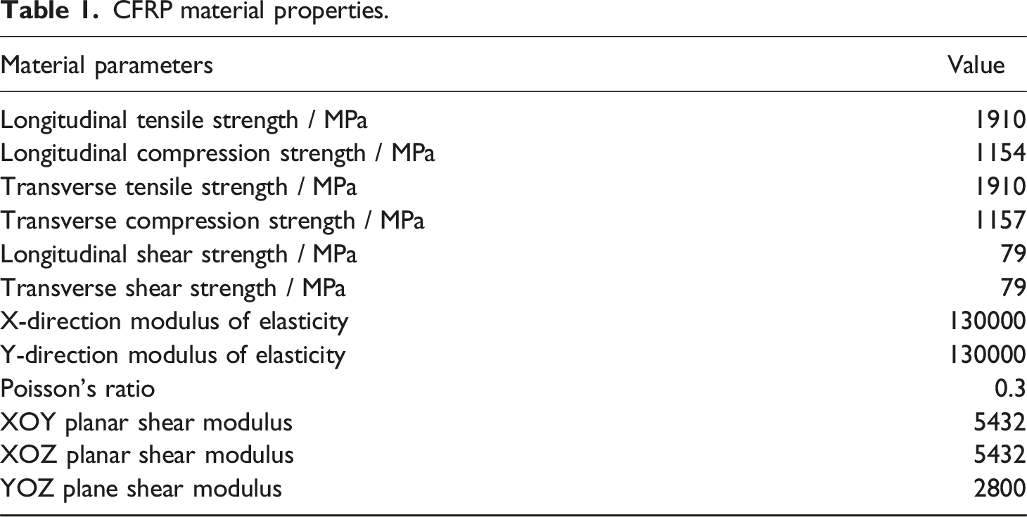
CFRP material properties.
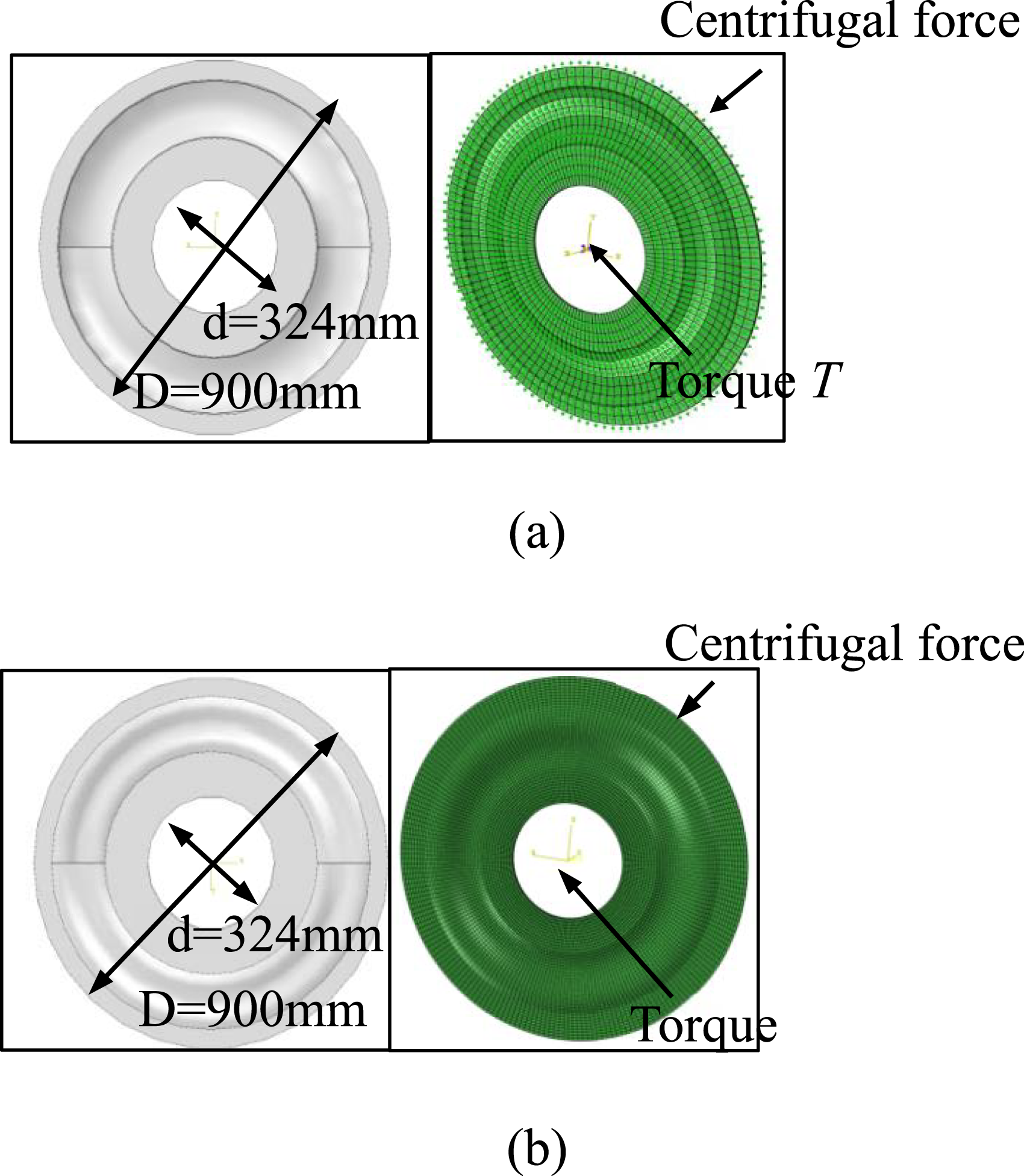
Geometric model and numerical model of circular curve and sine-wave curve membrane plate: (a) circular curve membrane plate, (b) sine-wave curve membrane plate.
Comparison of stress and strain distributions of composite membrane disks with the same layup but different curved surface forms under the same rotational speed and the same torque T is shown in Figure 2. Comparative analysis of stress and strain distribution of circular and sinusoidal curved membrane disk: (a) Stress map of a circular curved membrane disk, (b) Stress cloud of a sine-wave curved membrane disk, (c) Strain cloud of a circular curved membrane disk, and (d) Strain cloud of a sine-wave curved membrane disk.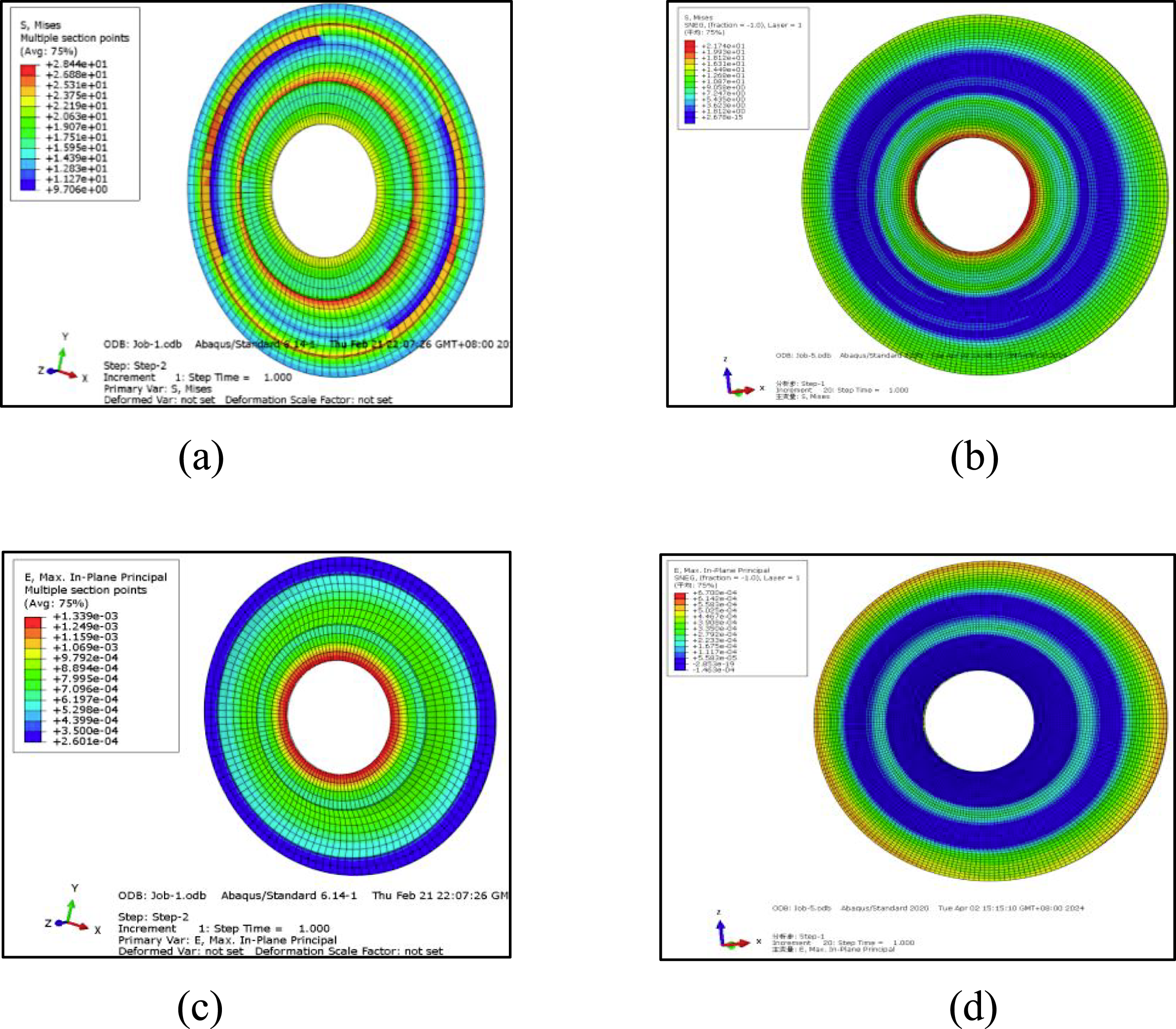
From the above figure, the stress distribution of the circular curved membrane disk ranges from 9.7 to 28.4 MPa , the stress distribution in the curved surface region ranges from 15.9 to 28.4 MPa;The overall stress distribution of the sine-wave curved membrane disk ranges from 1.8 to 21.7 MPa, the stress distribution in the curved surface area ranges from 5 to 12.7 MPa; The overall strain distribution of the circular curved membrane disk ranges from 260 to 1339 με, strain distribution in the curved surface region ranges from 529 to 889 με; The overall strain distribution of the sine-wave curved membrane disk ranges from 56 to 670 με, the strain distribution in the curved region ranges from 335 to 391 με. The sine-wave curved membrane disk is basically uniformly distributed.
It can be seen that the sinusoidal curved membrane disk has less stress in the overall and curved surface area compared to the circular curved membrane disk, indicating that the performance of the sinusoidal curved membrane disk is better than that of the circular curved membrane disk. The two curved membrane discs are formed by membrane compression molding and their manufacturing costs are similar, so the sinusoidal curved membrane disc is chosen next for the layup design due to its better performance.
Sine-wave curved membrane disk layup design and analysis
Analysis of the effect of layup angle
The effect of different layup angles on the ability of sine-wave curved membrane disk to transmit torque, axial displacement compensation and angular displacement compensation is firstly investigated, based on the methodology of literature. 27 A total of seven obliquely intersecting symmetric layup forms ([±θ]4S, totaling 16 layers) of sine-wave curved membrane disks with different layup angles were designed. Numerical analysis software (ABAQUS) was used to calculate and analyze the mechanical properties of sine-wave curved membrane disks in the form of diagonally intersecting symmetric layups ([0°]4S, [±15°]4S, [±30°]4S, [±45°]4S, [±60°]4S, [±75°]4S, and [90°]4S) with different layup angles under the action of the torque T (T = 12.5 kN.m), the axial displacement load D (D = 5 mm) and bending moment M (M = 0.025 kN.m).
Under the action of the same torque T (T = 12.5 kN.m), the calculation results of the maximum torsion angle and axial displacement on the sine-wave curved membrane disk with different diagonal symmetric layup angles are shown in Figure 3. Variation of maximum torsion angle and axial displacement of sine-wave curved membrane disk with different diagonal symmetric layup angles: (a) Maximum torsion angle variation, (b) Variation of the maximum axial displacement.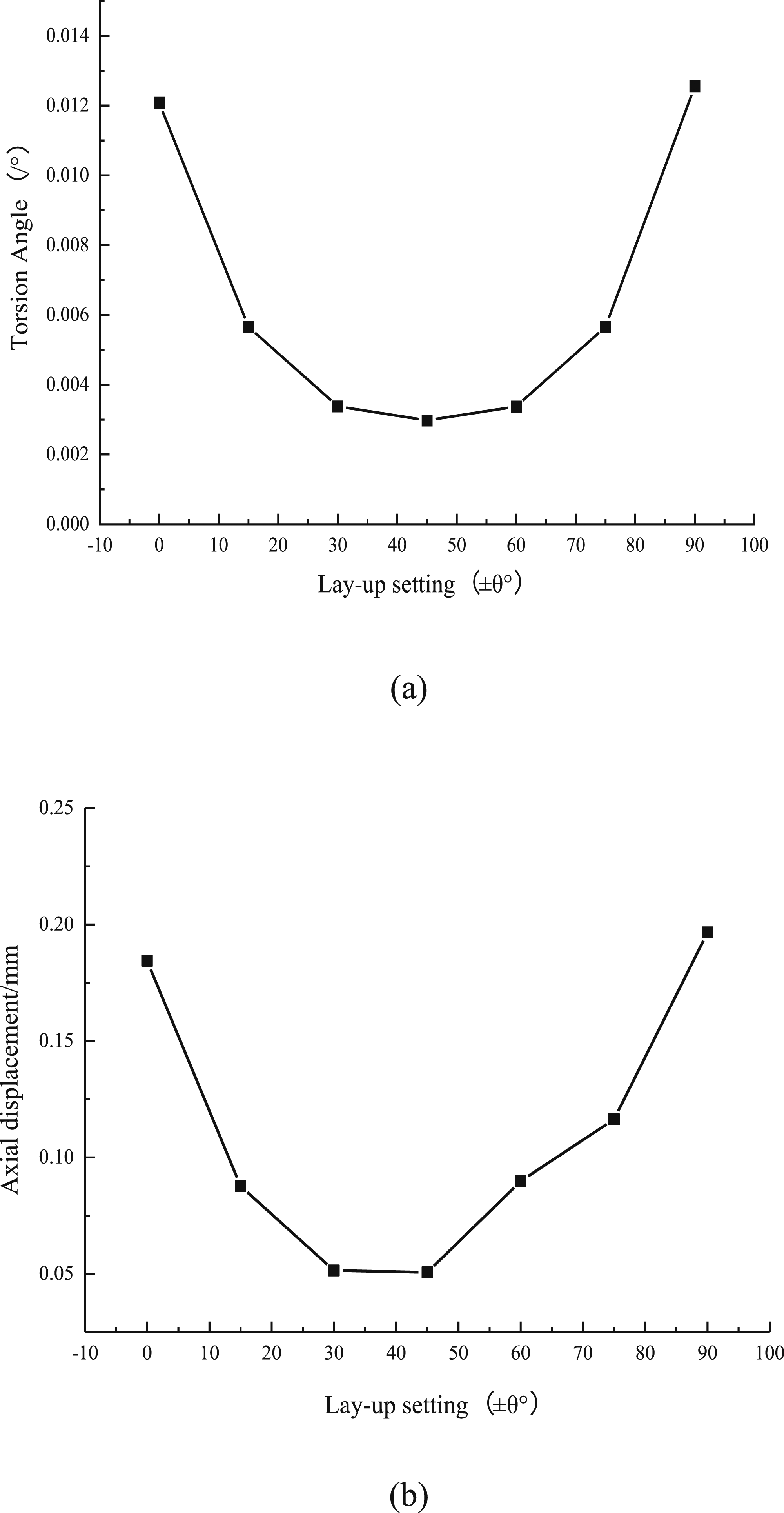
As can be seen from Figure 3, in the case of diagonal symmetric layup, the deformation of torsion angle and axial displacement produced on the curved membrane disk with different diagonal layup angles of sinusoidal wave under the action of the same torque T is minimized when the curved membrane disk adopts the form of diagonal symmetric layup of [±45°]4S. It is shown that this angled form of layup allows the curved membrane disk to have a high capacity to bear torque. Therefore, ±45° layup angle can be considered in the layup design of sinusoidal curved membrane disk.
Under the same axial displacement load D = 5 mm (Figure 4(a) shows the schematic diagram of the load and layup number), the maximum stresses within each layup in various diagonally symmetric layup forms of sine-wave curved membrane discs are shown in Figure 4(b). Maximum stress in each layer of sine-wave curved membrane plate structure with different oblique symmetric lay under axial displacement load: (a) Diagram of load and lay, (b) Maximum stress in each ply.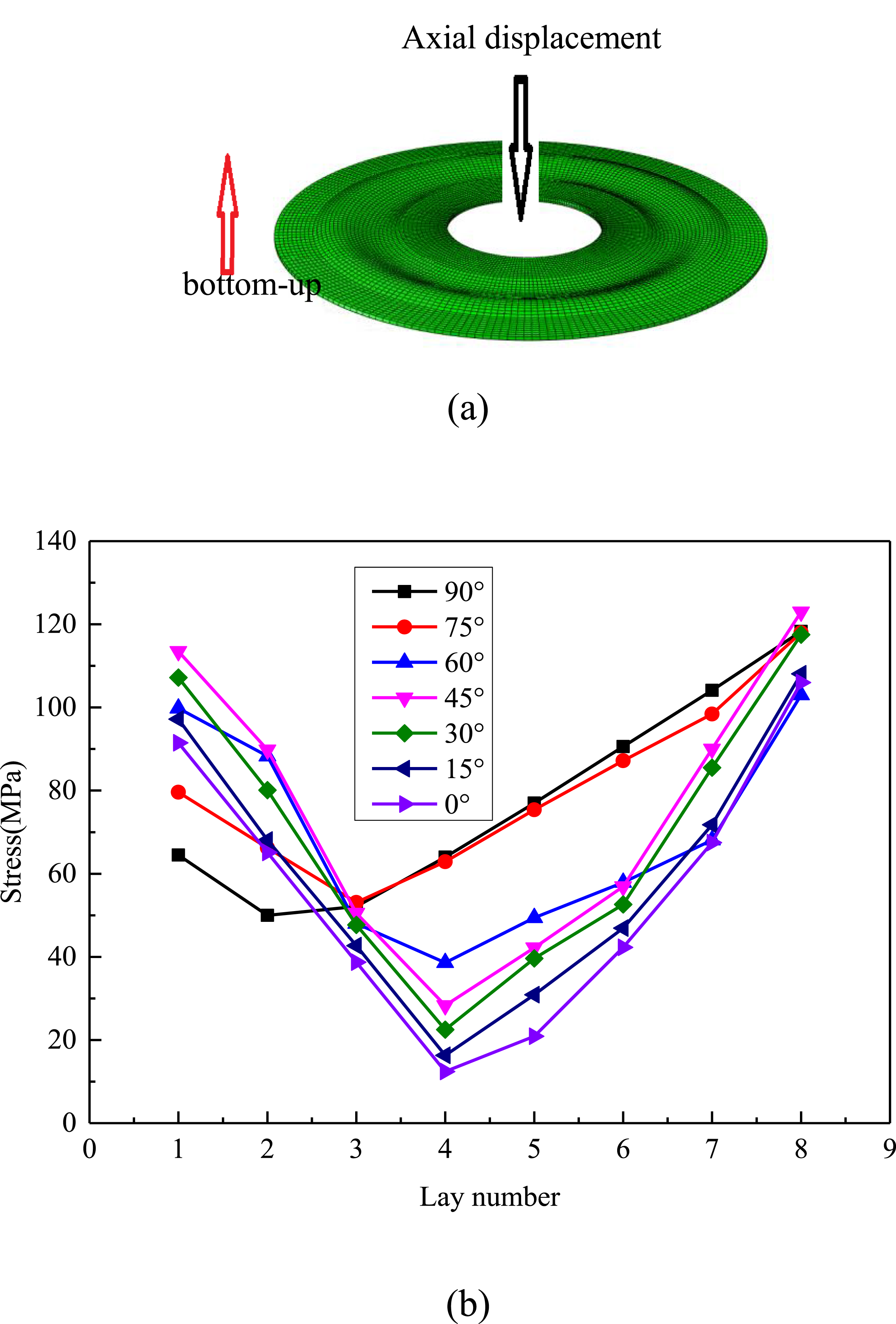
As can be seen from Figure 4, under the action of axial displacement load D = 5 mm, the sine-wave curved membrane disk in the form of 0°, 15°, 30° and 45° diagonally symmetrical layups is analyzed, and the maximum stresses within each layup are symmetrically distributed in the form of symmetrical distribution along the middle surface of the layups (layer 4), ang the upper and lower outer surface layers (layers 1 and 8) of the sine-wave curved membrane disk have the highest stresses; In contrast, the maximum stresses in the layers of 60°, 75°, and 90° sinusoidal surfaces are not symmetrically distributed in several types of diagonally symmetrical layups; Figure 4 also shows that [0°] 4S (fibers are laid in the radial direction of the sinusoidal curved membrane disk) obliquely intersected symmetrically laid sine-wave curved membrane disks produce the least stresses within each layup. The analysis results show that, in the axial displacement compensation process, the addition of 0° layers can increase the axial compensation ability of the sinusoidal curved membrane disk. Therefore, in the layup design of sine-wave curved membrane disk, 0° layup should be given consideration.
In addition, the distribution of stresses in various diagonally symmetrically laid CFRP sine-wave curved membrane disks under axial displacement load D (D = 5 mm) is shown in Figure 5. Stress distribution of [0°] 4S and [90°] 4S sine-wave curve membrane plate structure with oblique symmetrical lay: (a) [0°] 4S, (b) [90°] 4S.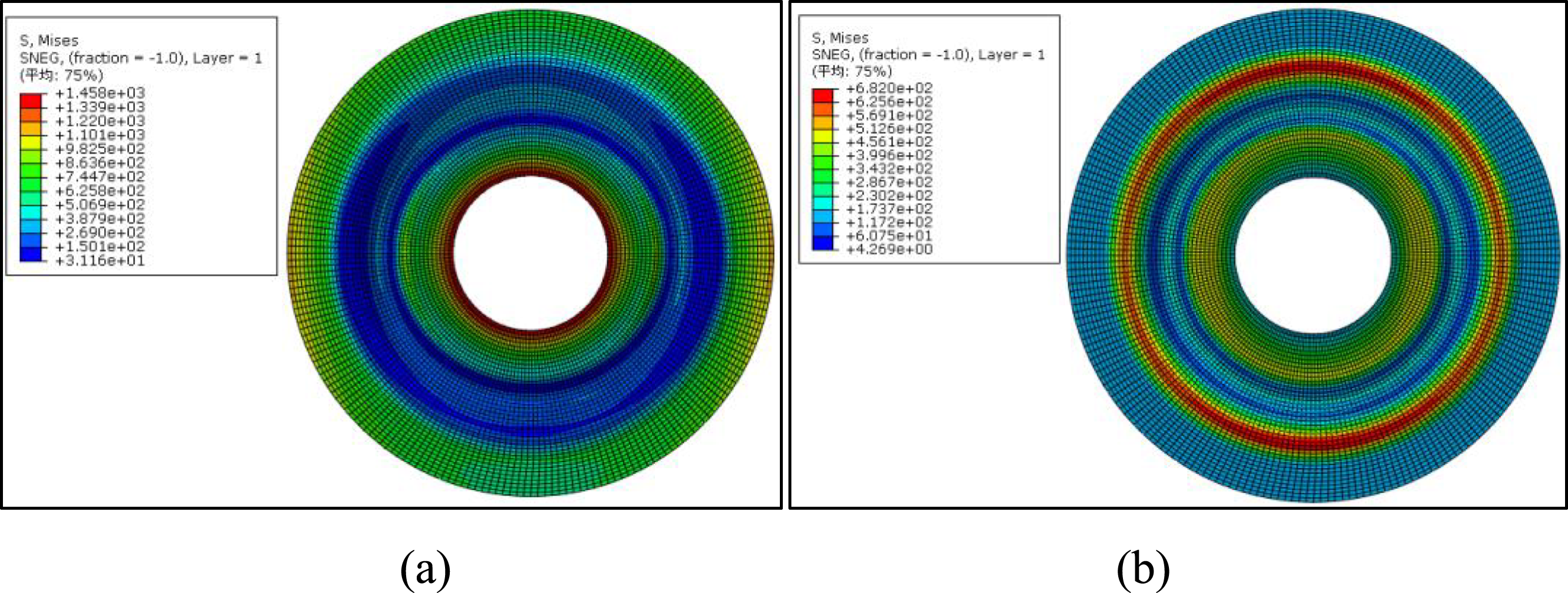
As can be seen in Figure 5, comparing the sine-wave curved membrane disks laid obliquely and symmetrically at [0°]4S and [90°] 4S, it is found that the internal stresses in the area of the [0°] curved surface are basically uniformly distributed. It is further stated that 0° layups should be considered in the design of layups for sine-wave curved membrane disks.
For the same bending moment M, the load applied to the sine-wave curved membrane disk and the layup sequence number are shown schematically in Figure 6(a), and the maximum stresses within each ply of various diagonally symmetric ply forms of sine-wave curved membrane disks under this load are shown in Figure 6(b). Maximum stress in each layer of sine-wave curved membrane plate structure with different oblique symmetric lay under bending moment M: (a) Diagram of bending moment M, (b) Maximum stress in each ply.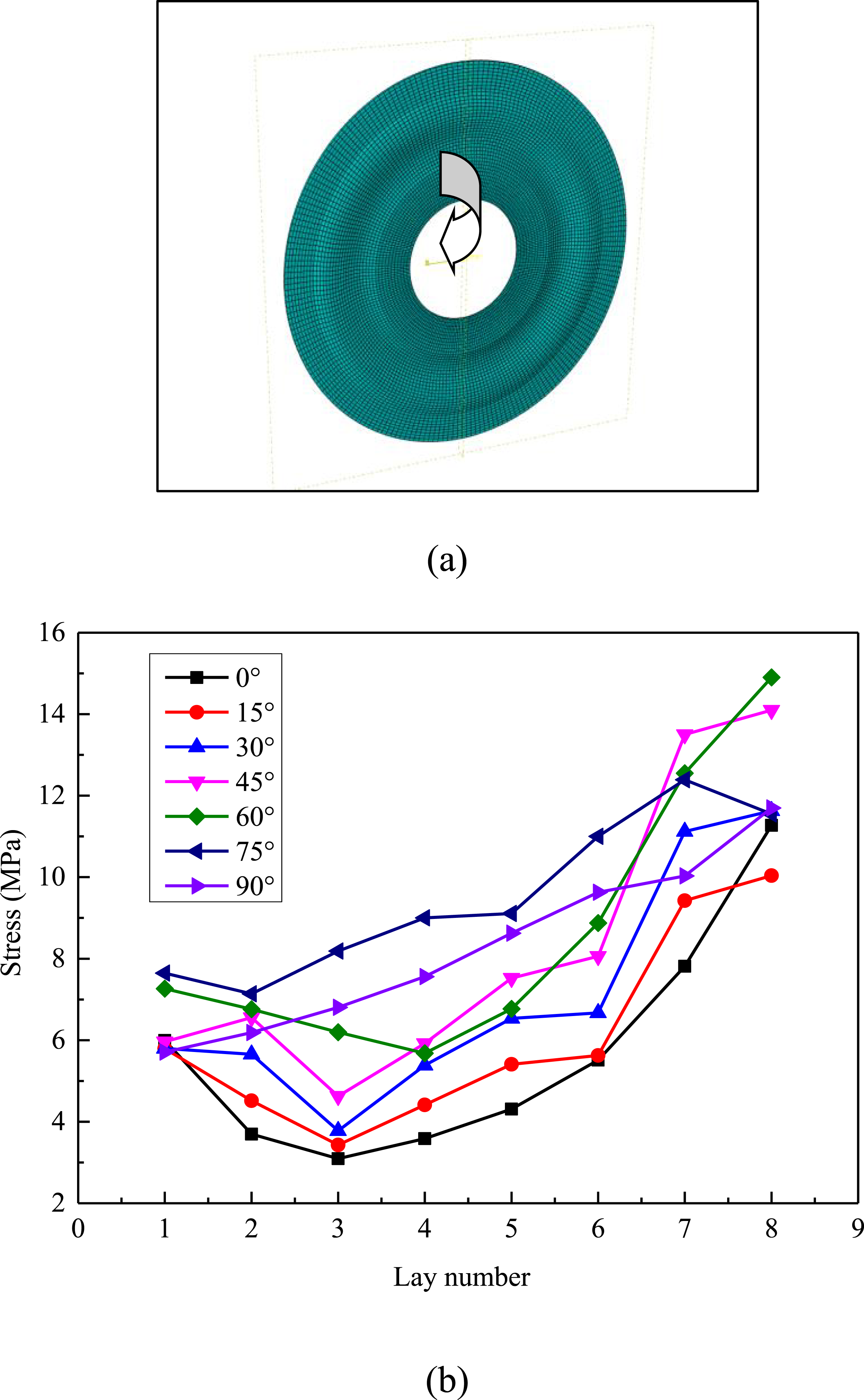
As can be seen from Figure 6, under the action of bending moment M, the maximum stresses within each layer of the sine-wave curved membrane disk with different diagonally symmetric layup forms are distributed asymmetrically along the layups, and the stress increases sequentially from the first layer to the surface layer. Stresses are minimized in a sine-wave curved membrane disk laid obliquely and symmetrically at [0°] 4S. The stress distribution in its layers shows a similar form of distribution when the pavements are set less than 45°. The stress distribution in the layers of the 90° diagonally symmetrically laid sine-wave curved membrane disk is relatively uniform.
From the above analysis process, it can be seen that the layup angles of 0°, ±45° and 90° should be fully considered during the design process of layup of sine-wave curved membrane discs. In order to better realize the function of transmitting torque as well as compensating axial and angular displacements with sine-wave curved membrane disks.
According to the conclusion of literature, 28 in order to make the sinusoidal curved membrane disk have high torque transmitting ability, the layup design of the sinusoidal curved membrane disk should ensure the content of 45° layup in the layup design. Secondly, in order to avoid the buckling phenomenon of sine-wave curved membrane disk structure in the process of transmitting torque, the proportion of 90° pavement should be appropriately considered in the process of pavement design.
Pavement design
The CFRP sine-wave curved membrane disks are computationally analyzed based on the above mentioned layup angles and proportions of different layup angles. Following the general principles of plywood design and taking into account the circumferential symmetry of the structure, the design of CFRP sine-wave curved membrane disk layup is carried out. This design realizes the ability of CFRP sine-wave curved discs to transmit torque and compensate for axial and angular displacements. After iterative analysis for optimization of different layup angle combinations, the final CFRP sinusoidal curved membrane disk layup form was determined as [0°/15°/30°/45°/60°/75°/90°/90°/-75°/-60°/-45°/-30°/-15°/0°]S.
The stress and strain distribution of the sine-wave curved membrane disk under a single load (torque T = 125 kN.m, axial displacement load D, bending moment load M = 250N.m) is shown in Figure 7. The results show that the maximum stress of CFRP sinusoidal curved membrane disk under single-torque condition occurs around the surface of the disk and the hole of the inner ring, and the resulting maximum strain is ≤ 1759 με, as shown in Figure 7(a). Under the single axial displacement loading condition, the maximum stress occurs at the circumference of the outer ring hole of the membrane disk, and the resulting maximum strain is ≤ 103 με, as shown in Figure 7(b). Under the single moment load condition, the maximum stress of the membrane disk appears near the surface and the hole of the outer ring of the membrane disk, which produces the maximum strain ≤632 με, as shown in Figure 7(c). Combining the above working conditions, the maximum stress on the CFRP sinusoidal curved membrane disk is ≤ 12.4 MPa, and the maximum displacement it generates is ≤ 1038με, as shown in Figure 7(d). The analysis results satisfy the design index of membrane disk. Stress and strain distribution of sine-wave curve membrane plate structure under single load and complex load: (a) Torque T, (b) Axial displacement D, (c) Bending moment M, and (d) Torque T、axial displacement D and Bending moment M.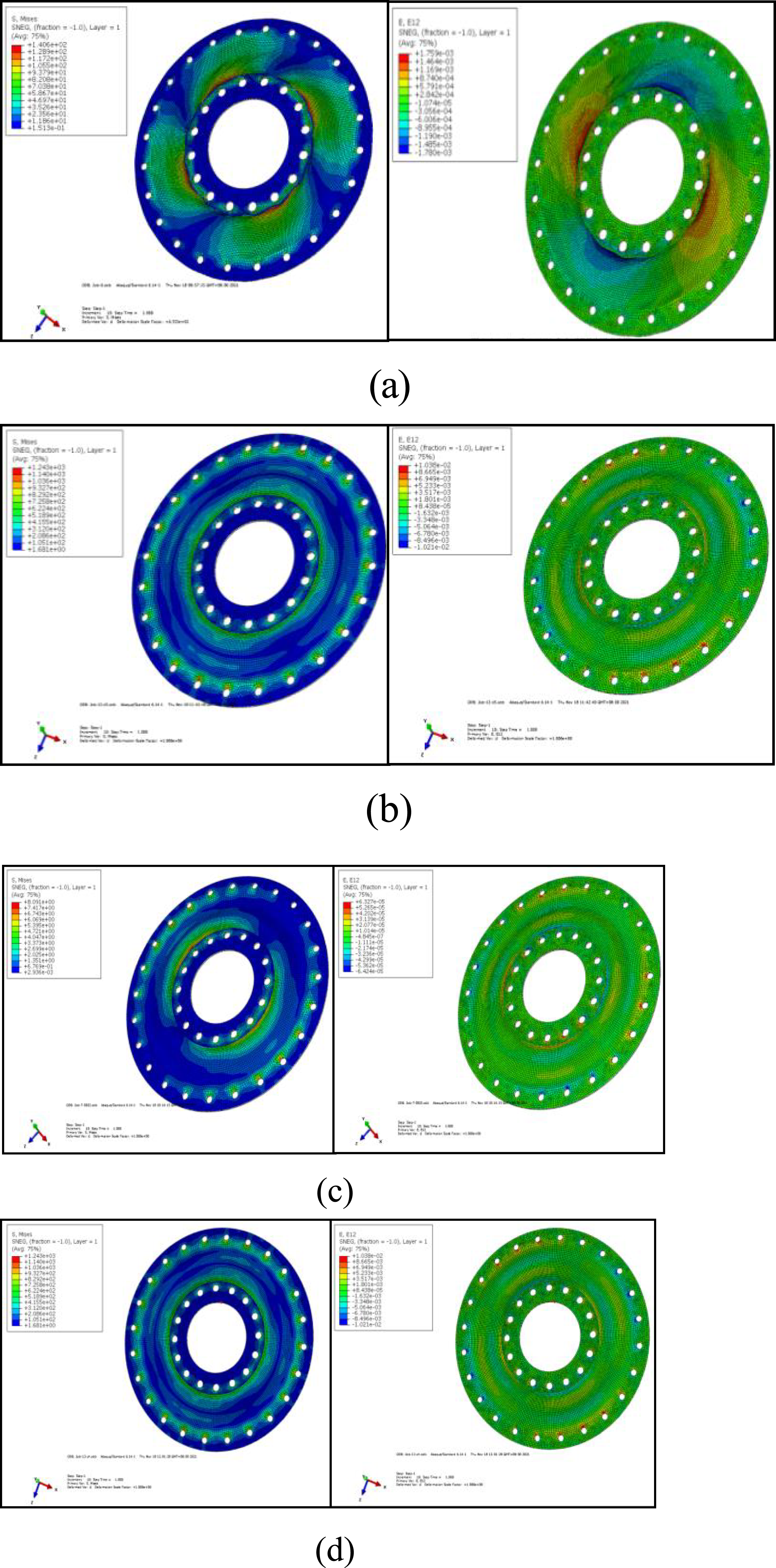
Fabrication of CFRP sine-wave curved membrane disks
To fabricate the CFRP sinusoidal curved membrane disk, Toray’s 12K T700S was used as the reinforcing phase of the composite, and the resin matrix was selected as epoxy resin 5228. It can be fabricated by the molding process, according to the characteristics of CFRP sinusoidal curved membrane disk structure. The general scheme of its fabrication can be referred to the literature. 28 The process in the design and production of the mold is as follows:
Mold design
Guide mechanism design
The role of the guide mechanism should not be ignored in the mold design process. The guide mechanism ensures accurate relative position of the convex and concave molds, precise mold clamping and smooth mold clamping process. At the same time, the guiding mechanism can withstand the lateral pressure of the melt inside the cavity on the cavity wall. Therefore, the design process of the guide mechanism of CFRP sine-wave curved membrane disk mold should take into full consideration of the thickness of the mold, the strength with sufficient resistance to lateral pressure (the mold material adopts 7075-T651 aluminum alloy), as well as the convenience of installation and other factors. Eventually, a 3 × 16 locating pin was selected as its guiding mechanism.
Design of demolding structure
First, the structural characteristics of the CFRP sine-wave curved membrane disk are analyzed to determine that the upper and lower molds are the same and the split surface is in the middle of the mold. Second, consider the shrinkage characteristics of the part. Mold design needs to be considered when the mold release problems, after research to make two kinds of mold release measures: (a) Since the resin system of the composite material shrinks due to heat and the adhesion decreases during heat curing, there is a possibility of automatic demolding of the part. Therefore, a 93° bevel with a certain accuracy level can be milled in the cavity with a CNC milling machine. (b) Five threaded holes are cut into the upper die of the mold, and demolding is achieved by bolting out the inserts through the bolt connection relationship. The mold structure is shown in Figure 8. Upper and lower molds of the mold and assembly drawing.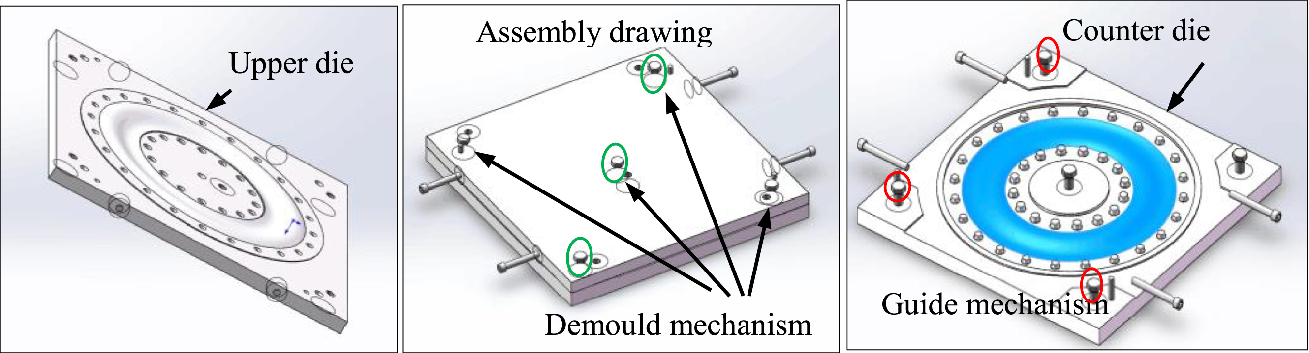
Curing molding
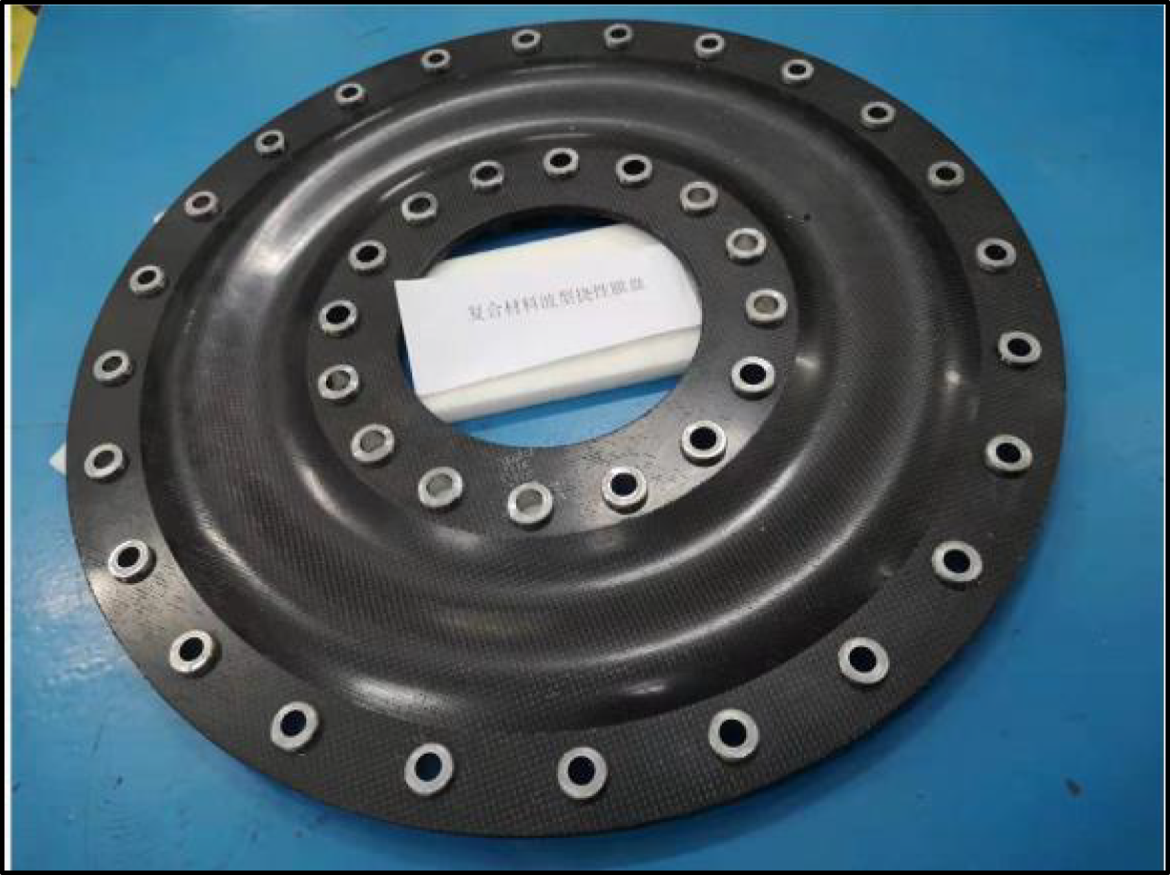
The prepreg is slit into the desired pattern of different angles and the layup of the structure is fabricated in accordance with the layup sequence, according to the conclusion of the layup design of the CFRP sine-wave curved membrane disk structure. The laying process of the membrane tray structure is as follows: cleaning of the mold, preheating of the prepreg, laying and closing the mold. And then, the curing and molding treatment was carried out according to the process parameters of the prepreg, and its curing history is shown in Figure 9. After the specimen is completely cooled, it is removed from the curing oven for final demolding and post-treatment processing. After demolding, the structure of CFRP sine-wave curved membrane disk is shown in Figure 10. Curing history of CFRP sine-wave curved membrane disk structure fabrication. CFRP sine-wave curved membrane disk structure.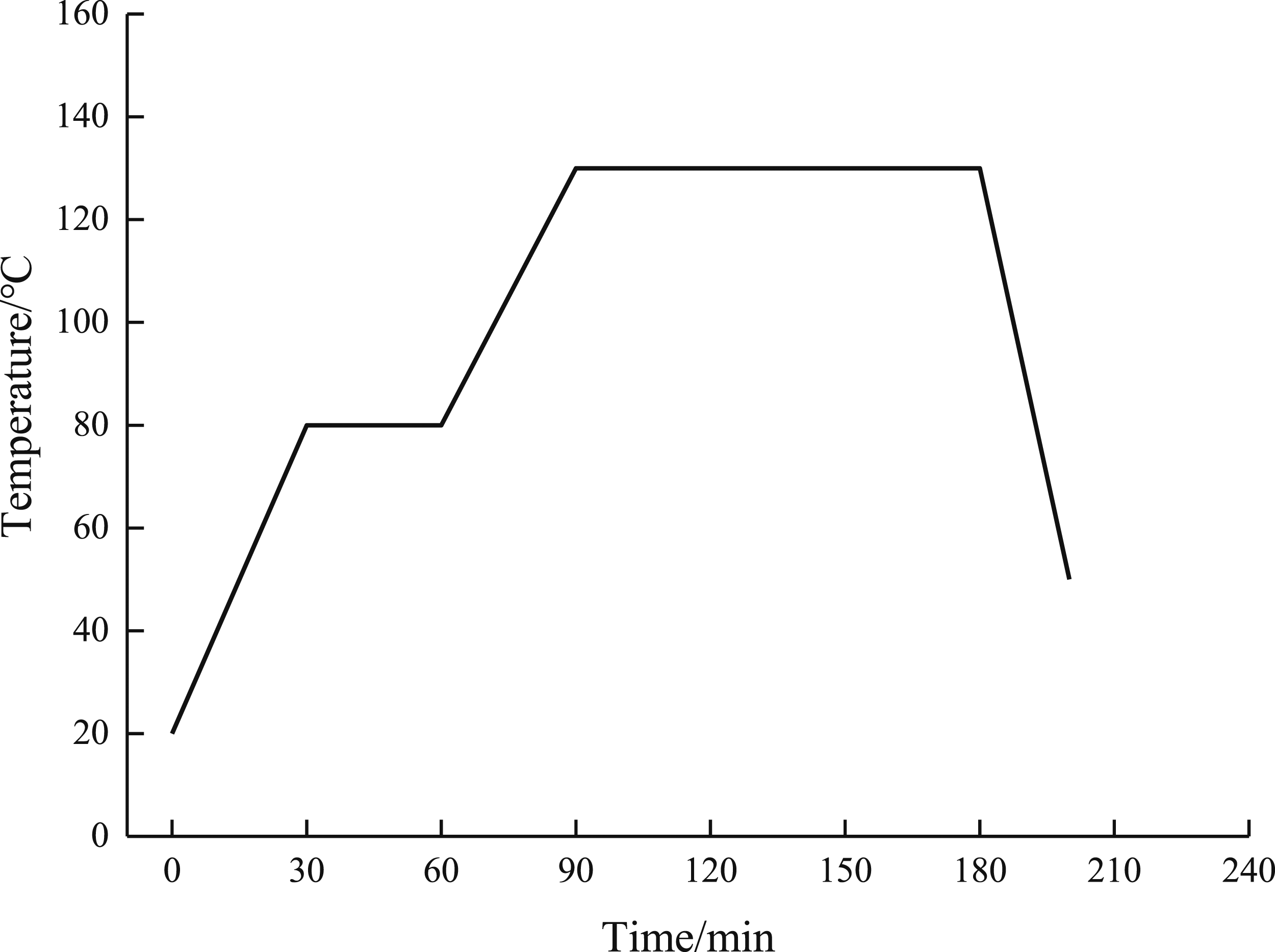
Experimental testing and analysis
Torsion test and analysis of results
A self-developed torsion testing machine was used to test the performance of CFRP sinusoidal curved membrane disk against axial impact displacement load and the strain distribution of each part during the axial displacement load. Measurement of the surface strain of a flexible coupling diaphragm disk by strain testing. The performance of CFRP sinusoidal curved membrane disks is analyzed and the correctness of the design calculation method is verified. Fix the outer ring hole of the membrane disk to the measuring fixture and add a washer in the inner ring hole. Apply axial displacement load to the washer with a pressure plate. A displacement loading test bench was used to load the membrane disk with 0 to 4 mm axial displacement load. A force transducer is used to record the loading force. A percentage table was used to record the displacement of the platen displaced at an angle of 120°.
A 45° strain gauge was attached to the front and back of the CFRP sine-wave curved membrane disk. The strain gauge was measured in three directions: tangential, radial and 45°. Strain gauge paste position 01 and 11 for the axial projection of the same position and the closest to the hub (0 for the front 1 for the reverse, the same below), 02 and 12 are axially projected in the same position and in the middle of the disk, 03 and 13 are axially projected at the same location and closest to the rim, 04 and 14 are the frontal crests with the opposite troughs, 05 and 15 are then at the frontal wave trough and the opposite wave peak. The location of the strain gauge paste is shown in Figure 11. The location of the strain gauges should be selected to ensure a uniform arrangement of the extended sine wave curve. To ensure the accuracy of the test, each group was measured 5 times and the average value was taken as the final test result. Position of strain gauge on the composite sine wave curved membrane plate structure in torsion test.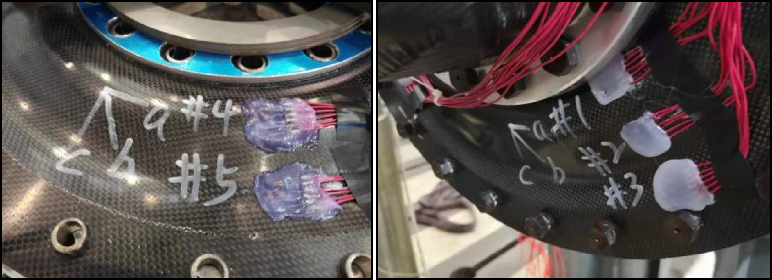
Apply a torque load T (T = 0 to 7.5 kN·m) using a torsion tester. JM5937 A dynamic strain tester was used to collect the values of the strain gauges at key locations, and the test results at test point 1 (which is the closest to the hub, so the strain generated here is the largest strain generated on the whole disk) were compared and analyzed with the simulation results. The test setup and a comparison of the test and simulation results are shown in Figure 12. Torsion testing and results for composite sine wave curved membrane plate structure: (a) Torsion test apparatus, (b) Comparison of test results and simulation results for point 1, and (c) Test results for points 2, 3 and 4.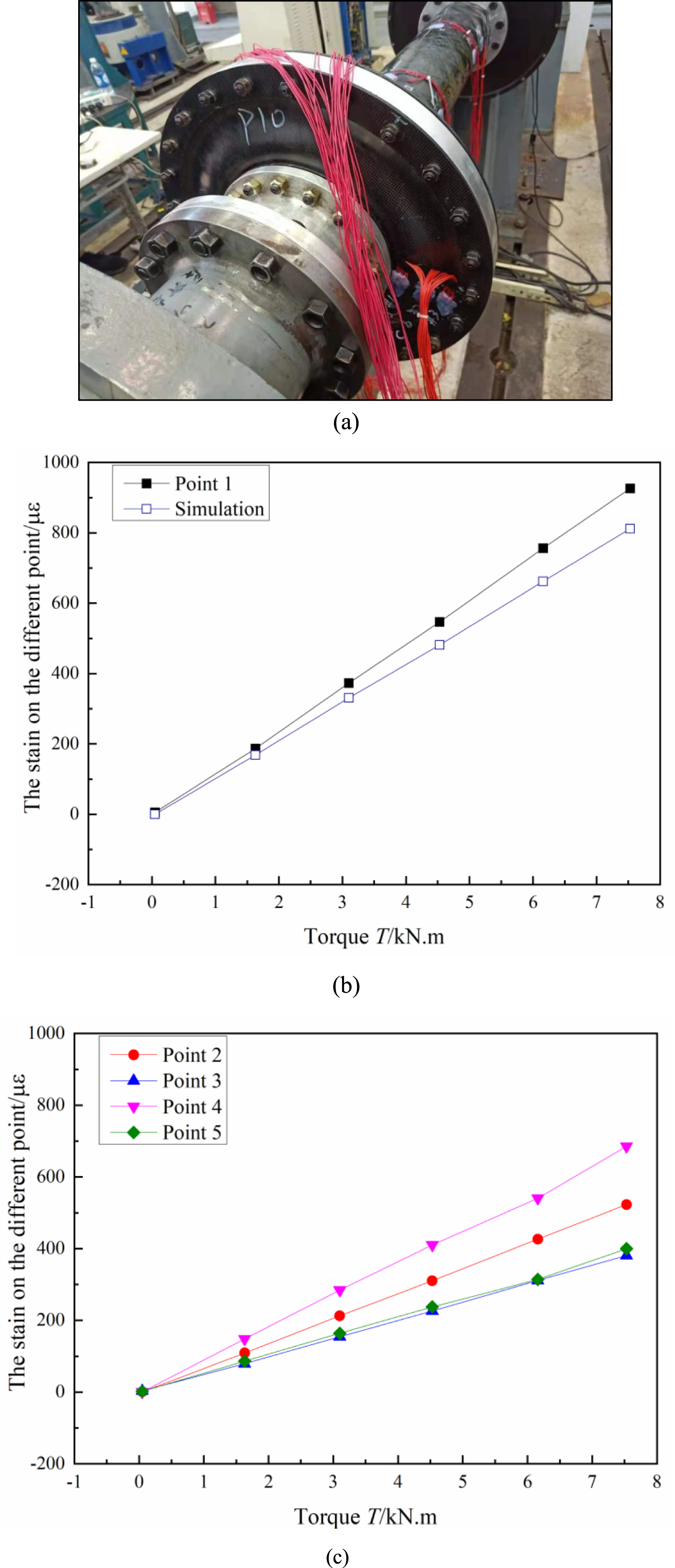
As can be seen in Figure 12(b) and (c), Points 1 to 5 correspond to the positions of the serial numbers labeled in Figure 11, respectively. the strain values at each test point increase as the torque T increases. The strain values at each test point along the radial direction from the center of the membrane disk to the edge of the disk gradually become smaller for the same load, Maximum strain generated at test point 1. The maximum strain generated at test point 1 is about 927 με, which is much smaller than the failure strain of CFRP structure (5000∼8000 με) when the torque T = 7.5 kN.m, it is shown that the structure can transmit a torque of at least 7.5 kN.m. In addition, it can be seen from Figure 12(b) that the simulation results for test point 1 are lower than the experimental results, and the value of the difference between the two increases as the load increases. The main reason is that the CFRP sine-wave curved membrane disk is in a completely ideal state in the simulation process. That is, between the fiber and resin in a single layer and between the layers are perfect bonding state, while the actual components in the production process are bound to have certain defects. Therefore, the torsion test test results of CFRP sine-wave curved membrane disk are larger than the theoretical values.
Axial compensation ability test and result analysis
The experimental procedure for testing the axial compensation capability of CFRP sinusoidal curved membrane disk is as follows: First, fix the outer ring hole of the membrane disk to the measuring fixture and insert a washer in the inner ring hole; Secondly, the pressure plate is utilized to apply an axial displacement load of 0∼4 mm to the washer; Finally, the displacement was recorded with a displacement percentage meter, while the loading force was recorded using a force transducer, and strain gages were used to collect the strain at key locations. The test setup is shown in Figure 13. Axial compensation ability test of composite sine wave curved membrane plate structure.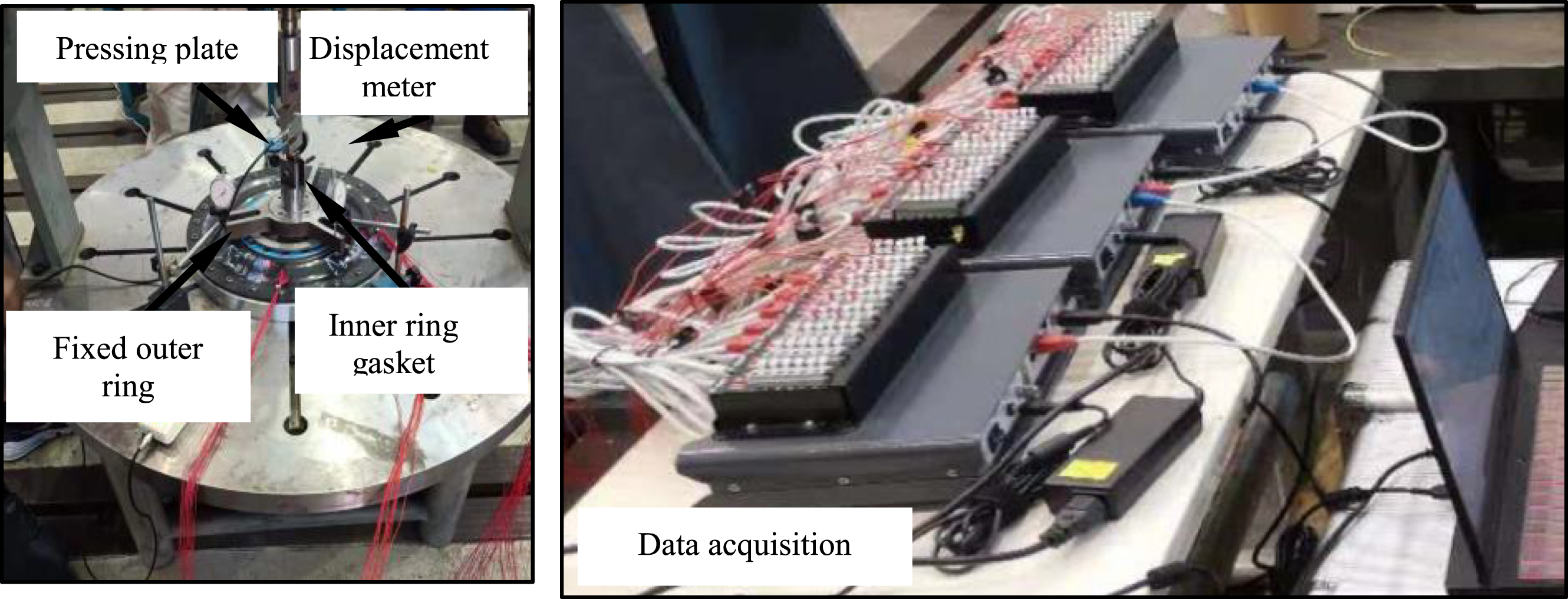
The strain distribution at each test point of the CFRP sine-wave curved membrane disk under axial displacement load, and its stiffness profile are compared with the simulated values in test and simulation. As shown in Figure 14. Comparison of experimental and simulated stiffness curves of composite sine-wave curved membrane plate: (a) Strain distribution at the test point, (b) Comparison of experimental and simulated stiffness curves.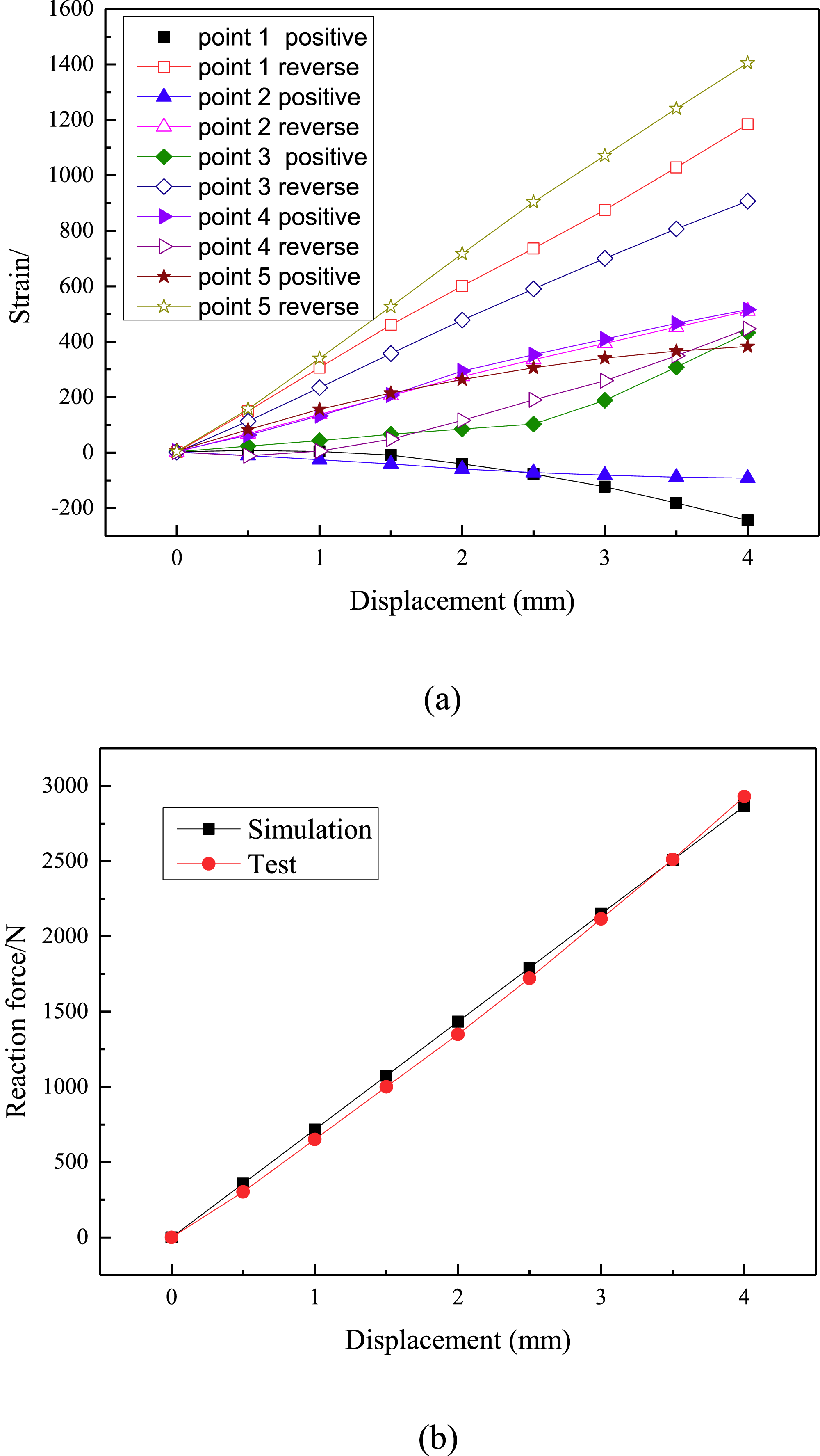
From Figure 14(a), Points 1 to 5 correspond to the positions of the serial numbers labeled in Figure 11, respectively. it can be seen that, under the action of axial displacement load, the strains of CFRP sinusoidal curved membrane disk at the same position on both sides of the disk are asymmetrically distributed, and the strain values at the back side of the disk are higher than those at the front side of the disk, and along the radial direction from the center of the disk to the edge of the disk the strain values of the test points do not show a gradual decrease in the tendency of strain values. The distribution is characterized by εpoint 5 > εpoint 1 > εpoint 3 > εpoint 2 > εpoint 4. The main reason for this is that the structure adopts the design of waveform surface, the backside of test point 4, that is, the trough position of the backside of the membrane disk produces the smallest strain, test point 2 is located between the peak and the trough of the structure, so it produces smaller strain, and the backside of test point 5, that is, the peak position of the backside of the membrane disk produces the largest strain, with a maximum of 1400 με, which is much smaller than the failure strain of CFRP structure (5000∼8000 με), indicating that the structure can provide high axial displacement compensation (at least 4 mm of axial displacement compensation can be provided). Meanwhile, it can be seen from Figure 14(b) that the experimental values of the axial stiffness of the structure fit perfectly with the simulated values, which further demonstrates the accuracy of the numerical model developed in the research process, which can be used to further analyze the other properties of the structure.
Conclusion
Combined with the numerical analysis software to design the curved surface form of curved membrane disk, and on the basis of which the layup design of CFRP curved membrane disk with sine-wave form was completed. The molding process was used to make it, and the following conclusions were obtained through a large number of experimental tests and analytical studies: (1) The maximum stress is distributed on the surface of the circular curved membrane disk, and the maximum strain is concentrated at the edge of the bore. The maximum stress distribution of the sinusoidally curved membrane disk is at the edge of the inner hole, and the maximum strain is at the outer edge of the membrane disk. The smaller stress and strain distribution of the sinusoidal curved membrane disk compared to the normal circular curved surface indicates that the performance of the sinusoidal curved membrane disk is better. Therefore, the sinusoidal curved membrane disk is identified as the final design surface. (2) The analysis of the effect of layup angle and the effect of the ratio of different layup angles, as well as the study of the effect of fiber layup angle on the structural properties of composite curved membrane discs can be seen: the ±45° fiber layup angle is conducive to improving the torsional strength of the curved membrane disc, the 0° fiber layup angle can improve the axial displacement compensation ability of the curved membrane disc, and the 90° fiber layup angle can enhance the angular displacement compensation ability of the curved membrane disc, and the layup form of the CFRP sine-wave curved membrane disc is determined to be [0°/15°/30°/45°/60°/75°/90°/90°/-75°/-60°/-45°/-30°/15°/0°]S after repeated calculations. (3) The modeling of CFRP sine-wave curved membrane disk has been verified to be accurate by comparison of torsion and compensating capacity test experiments. Composite sine-wave curved membrane discs molded in a layup scheme are capable of transmitting a torque of 7.5 kN.m, while their axial displacement compensation capability of up to 4 mm enables them to be used as required. (4) The CFRP sinusoidal curved membrane disk designed in this work is mainly used in the marine field, which requires the disk to have the advantages of high strength and high torque transmitting ability. In order to fully utilize the material in the desired load-bearing region, future research can be considered for CFRP planar variable thickness membrane disk structures.
Footnotes
Declaration of conflicting interests
The author(s) declared no potential conflicts of interest with respect to the research, authorship, and/or publication of this article.
Funding
The author(s) disclosed receipt of the following financial support for the research, authorship, and/or publication of this article: This research is supported by the Science Foundation of National Key Laboratory of Science and Technology on Advanced Composites in Special Environments (Grant no. JCKYS2023603C022); This research is supported by the Natural Science Foundation of Heilongjiang Province of China(Grant no. LH2023E114); This research is supported by the Basic Research Support Program for Outstanding Young Teachers in Undergraduate Colleges and Universities in Heilongjiang Province (Grant no. YQJH2023144); This research is supported by Basic Research Operating Costs of Undergraduate Colleges and Universities in Heilongjiang Province Scientific Research Projects (Grant no. 2022GJ03); This research is supported by Dragon River Engineering Fledgling Goose Innovation Team Support Program (Grant no. CY202302).