
Abstract
A multiple-reinforced steel-plastic composite pipe (MRSPCP) is a new type of composite pipe developed in China recent years. The MRSPCP is composed of high-density polyethylene (HDPE) matrix, steel-wire mesh, and steel strip. It is an improved version of the traditional structural wall pipe, and it is able to carry both external and internal pressures. Nowadays, it has been employed in many projects that require large diameter and high flow media transportation, such as water distribution systems, drainage systems, agricultural irrigation systems. As the MRSPCP is newly developed, its mechanical properties and failure mechanism are not clear, and its design method lacks theoretical basis, so this paper carries out the experimental, theoretical and simulated research to investigate the short-term mechanical properties of the MRSPCP. Firstly, uniaxial tensile tests are carried out to acquire the mechanical properties of the constituents. As the steel wire is curly and it is hard to get the stress-strain relationship directly, an inverse identification method was applied to determine the mechanical parameters of a bilinear model representing the steel-wire mechanical behavior. Moreover, short-term burst tests of the MRSPCP are carried out to assess its mechanical performance and provide data for the verification of the theoretical and simulated research. Secondly, a theoretical model is established to calculate the failure pressure by constructing force equilibrium relationship along the axial and hoop directions of the MRSPCP respectively, based on elastic mechanics. In the end, a finite element model of MRSPCP is established, considering the nonlinear mechanical property of the materials. Both the theoretical and the simulated results agrees well with the burst test result, with the relative error of only −13.18% and −4.41% respectively. As the finite element model not only provides more accurate result, but also it can demonstrate contour plots of different constituents inside the MRSPCP, the model is used to study the effects of the pipe thickness, composite strip winding angle and steel-wire diameter on the mechanical properties of MRSPCP. This study might be a guide for the design and safe application of the MRSPCP and similar composite pipes.
Introduction
After railway, road, water and air transport, pipeline transport has become the fifth mode of transport, with its economic, efficient and safe and reliable advantages, and has become an indispensable part of the modern social economy. The existing pipes in the market have a wide variety due to the different application scenarios and performance requirements, but as the demand for pipe transportation evolves, new pipes are constantly being developed. Especially for the drainage pipe, there are many commonly used pipes, and among these pipes, ductile iron pipes1,2 and polyethylene (PE) structure-wall pipes
3
stand out. However, as the climate becoming more extreme and deficiencies in pre-existing urban planning,4,5 urban flooding is occurring more frequently and more severe,6,7 as shown in Figure 1, so demand for pipes that can withstand internal pressure is gradually emerging, because that kind of pipe can be used to pump away flooded water in combination with pumping machine, besides meeting daily drainage needs.
8
Urban flooding across the globe. (a) Houston, USA. (b) Beijing, China. (c) Karachi, Pakistan. (d) Saratov, Russia.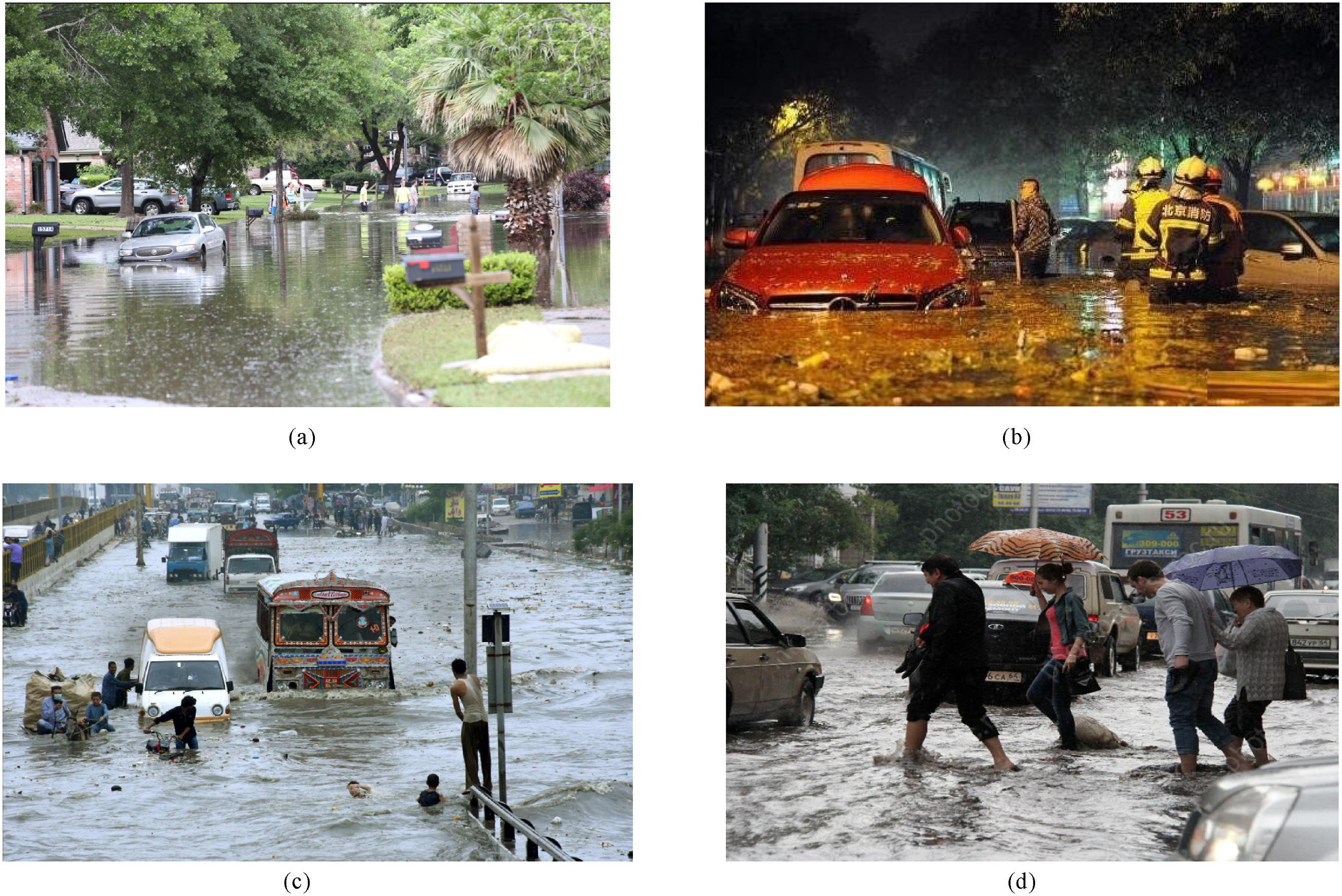
A ductile iron pipe has a good bearing capacity and impact resistance, which is suitable for urban water supply, sewage discharge and industrial fluid transportation. However, the weight of ductile iron pipe is heavier, the transportation and installation cost are higher, and the most worrisome aspect is that its resistance to chemical corrosion is not as good as plastic materials. A PE structure-wall pipe, which is characterized by light weight, corrosion resistance, easy construction, is suitable for large drainage systems, but it can hardly bear internal pressure to meet current requirements for urban flooding, due to its limited mechanical strength. Therefore, multiple-reinforced steel-plastic composite pipe (MRSPCP) has been developed in recent years to meet the requirements of more complex working conditions, including undertaking internal pressure and external radial load simultaneously. MRSPCP is just the needed new type of composite pipe. The actual appearance of the MRSPCP is shown in Figure 2(a), and its unique structure is shown in Figure 2(b). MRSPCP is a kind of composite pipe made of high-density polyethylene (named HDPE) as base material, and steel strips and steel-wire mesh as reinforcements. The reinforcements and matrix are closely bonded by adhesive resin, as shown in Figure 2(b). Compared to other steel-plastic composite pipes, MRSPCP possesses better mechanical performance due to its unique structure. The outer layer of the wrapped steel strips is specifically designed to increase the resistance of the pipe to external loads, and the inner layer of the steel-wire mesh reinforcement effectively ensures the bearing capacity of the internal pressure,
9
which brings about great potential for large-diameter, large-flow and long-distance media transportation applications for the MRSPCP in different industrial areas,
10
such as power engineering, chemical industry, public equipment, etc.11,12 Schematic diagram of MRSPCP pipe structure. 1-MRSPCP body, 2-steel strip, 3-Steel-wire Mesh.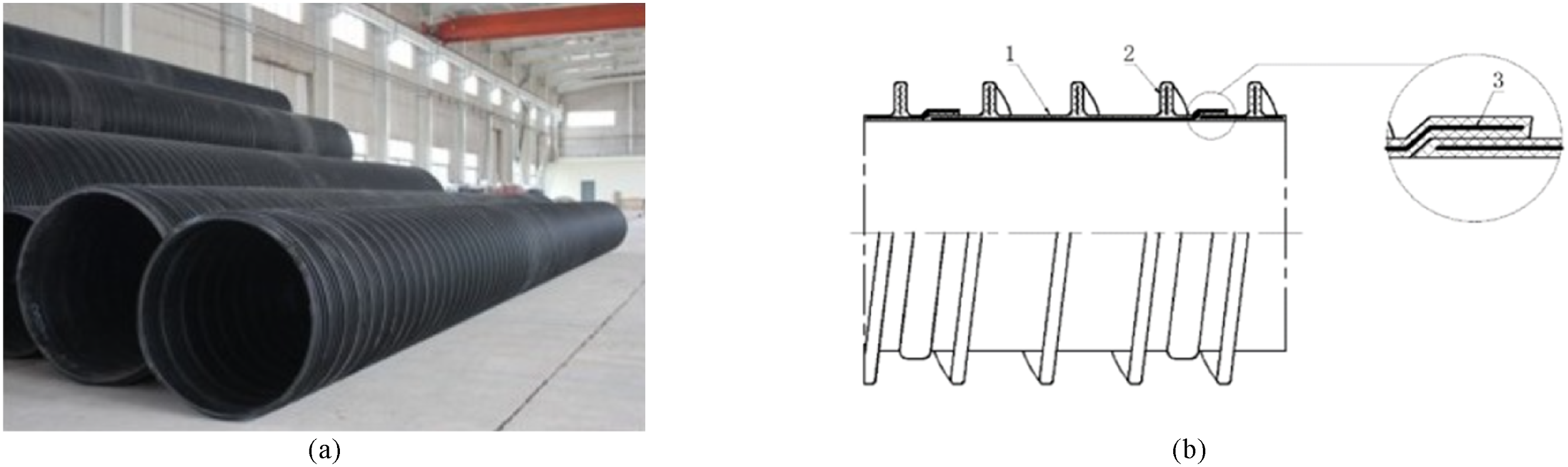
However, current MRSPCP production can only rely on empirical methods, as the MRSPCP manufacturers lack theoretical design methods and analysis methods for predicting the short-term performance of the pipe based on its structural and material parameters. What’s more, it is also unknown that the load carrying proportions of the MRSPCP’s various components and the failure mechanism when undertaking internal pressure. These are the bottlenecks for safety assurance of MRSPCP systems and development of new products with high parameters and specifications. Thus, it is imperative to investigate the short-term mechanical properties of the MRSPCP and develop a method for predicting the short-term failure load. This study is mainly focused on the mechanical performance of the MRSPCP under internal pressure.
At present, none of studies has been reported on the mechanical properties of the MRSPCP all over the world. Fortunately, there are a lot of earlier publications on the short-term mechanical properties of many other kinds of composite pipes, involving experimental investigations, theoretical analysis, and numerical simulation. Xia et al. 13 Xia, based on classical laminate-plate theory, investigated the elastic solutions of thermal stress and thermal strain in fiber-wound sandwich tubes under internal pressure and temperature changes. The thermal stress analysis of a typical three-dimensional, cylindrical, orthogonal anisotropic sandwich pipe is carried out. The stress and deformation of sandwich tubes with different winding angles are analyzed by computer program. In addition, the optimum winding Angle of filament winding fiber reinforced material was designed by netting approach analysis. It provides the direction for the subsequent research of pipe winding Angle and product design. Shi Jun. 14 the performance of polyethylene pipe reinforced by wound steel-wire (PSP) in industrial applications, especially in the face of different ambient temperatures, was studied. The temperature-dependent elastic modulus is obtained from the uniaxial tensile test of HDPE at different temperatures, which is the key basis for evaluating the performance of PSP. Based on classical laminate theory, an innovative prediction model was developed to quantify the short-term burst pressure of PSP at different temperatures, taking into account in particular the mechanical properties of HDPE matrix with respect to temperature. In addition, in order to verify the accuracy of the model, PSP burst tests were carried out under a series of temperature conditions. The results show that the theoretical prediction is highly consistent with the actual test results, and the relative error range is controlled between 6.72% and 8.82%. The experimental results not only confirm the validity of the model, but also provide practical evidence of the relationship between temperature and performance. The error limit provided by the research provides a valuable reference for engineering design and PSP application, and the comprehensive application of theoretical analysis and experimental data provides a solid scientific basis for the optimal design and operation of PSP.
Satoshi Kobayashi et al. 15 predicted the burst pressure of fiber wound reinforced composite pipe based on the maximum strain criterion. The strength of the composite pipe is analyzed by multilayer elastoplastic analysis. The calculated results of stress, strain and deformation of the composite pipe are in good agreement with those obtained by the finite element method. The research shows that the strain is a function related to the internal pressure. With the increasing of the internal pressure, the hoop strain of the composite pipe also increases gradually. When the internal pressure increases to a certain value, the hoop strain reaches the failure strain, then the internal pressure is considered as the burst pressure. M.P.Kruijer et al. 16 used plane stress and plane strain assumptions respectively to analyze the mechanical properties of the steel-wire reinforced plastic composite pipe, and also considered the nonlinear behavior caused by the change of winding Angle and radius of the composite pipe under internal pressure. If the plane stress is uniformly distributed along the wall thickness of the composite pipe, the ratio of hoop stress to axial stress is 2:1, while if the stress is unevenly distributed along the wall thickness based on the plane strain assumption, the ratio of hoop stress to axial stress is 2.25:1. The results show that the calculated results of plane strain hypothesis agree better with the experimental results. Liang Ju. 17 studied a new type of composite pipe with high-density polyethylene as the matrix and steel-wire rope belt as the reinforcement body. Through the burst test of the pipe and the establishment of Ansys finite element model, the force-displacement change of the steel-wire rope reinforced plastic composite pipe and the steel-wire rope under load is analyzed, and the changing trend of the blasting pressure and elastic deformation limit pressure of the composite pipe is obtained. Toh, W. 18 studied the material characterization of wound fiber composite pipe, reversely applied the stress homogeneity theory of the composite pipe, and obtained the corresponding layer properties of the fiber wound pipe through continuous iteration. The results showed that the obtained layer properties could accurately predict the response of pipes of various sizes.
Kobayashi et al. 19 conducted an elastic-plastic analysis of the filament-wound carbon fiber-reinforced plastic hybrid composite pipes under internal pressure. Based on the maximum strain criterion, the blasting strength and impact damage residual rupture strength of the pipe are predicted. Zhang et al. 20 put forward the analytical solution of the blasting pressure of a thin-walled pipe with a long end cap under the action of plastic anisotropy and external pressure, and discussed the influence of plastic anisotropy and external pressure on the blasting pressure. Shi et al. 21 considered the nonlinear problem of PSP base material, and established a new finite element model, using element modeling of steel-wire and HDPE, The wire mesh and HDPE are modeled separately, while ensuring the spiral shape of the structure, more close to the real situation. The results of linear elastic model, nonlinear model and burst test are compared at the same time. The difference between nonlinear model and linear model is also discussed. Wang et al. 22 established two models to study the mechanical behavior of reinforced thermoplastic pipes under internal pressure. The influence of winding Angle and diameter‐to‐thickness ratio on the first‐ply failure pressure and the ultimate burst pressure is obtained, and a method for studying failure pressure is proposed. Yao et al. 23 conducted burst tests on thermoplastic composite pipes with different reinforced layers, proving that the progressive damage model is more applicable to thermoplastic composite pipes. At the same time, the parameterization of the winding angle of the pipe was studied. Xu et al. 24 studied the failure mode, short-term burst pressure and strain of Cross-winding steel-wire reinforced thermoplastic pipes under internal pressure, and discussed the effective plastic strain of HDPE inner liner and outer sheath. The relationship between the ultimate bearing capacity and the steel-wire strength is also discussed. A new three-dimensional finite element model of blasting failure is presented.
Finite element analysis (FEA) has become an effective tool to evaluate the damage behavior of composite tubes under different load conditions. For example, Maziz, A. 25 studied the impact-induced damage of hybrid composite tubes under compressive stress through finite element analysis, and the results showed that the impact load would not only lead to local damage of composite tubes, but also cause internal interlayer cracks and fiber fractures, thus reducing their bearing capacity. In another study, Maziz, A. 26 proposed a progressive damage model for evaluating prestressed hybrid wound composite pipes under low-speed impact. The research shows that the low-speed impact will cause the surface of the composite pipe to sag and delamination, and these damages will further expand under the action of internal pressure, and eventually lead to the failure of the pipe. This model can accurately predict the damage evolution process of composite tube under different impact energy and internal pressure conditions, and provides an important reference for the design and optimization of composite tube. In addition to impact damage, drilling operation is also a common processing process for composite tubes in practical applications, but this process may introduce additional damage, which affects its mechanical properties. Morkavuk, S 27 systematically studied the effects of drilling damage on the toroidal tensile and fatigue behavior of carbon fiber reinforced plastic (CFRP) pipes. The results show that thermal damage and mechanical damage during drilling can significantly reduce the toroidal tensile strength and fatigue life of CFRP tubes. In addition, the quality of the hole (such as aperture, shape and surface roughness) also has an important effect on the mechanical properties of the composite tube. Through finite element analysis and experimental study, these damage mechanisms and their effects on the properties of composite tubes can be understood more comprehensively, and scientific basis can be provided for the design and manufacture of high-performance composite tubes.
Shao et al.23 studied the blasting of the perforated steel strip composite pipe at different temperatures, and proposed the formula for calculating the blasting pressure. It is shown that the material of perforated steel layer is isotropic and Diameter thickness ratio has direct influence on the pressure resistance of the pipe. Xu et al. 28 studied the rupture pressure of Fiber-reinforced flexible pipes with arbitrary busbars under internal pressure based on the composite shell theory and transfer matrix method. A theoretical method to simplify the transfer matrix by linear equation is presented. It is shown that the optimal winding Angle of unidirectional fabric has a significant effect on the blasting pressure of pipe. Gao et al. 29 studied steel reinforced flexible pipe, discussed the mechanical response of stress of PE layer and steel strip, verified the hypothesis of strain uniformity of steel strip section, and showed that limited increase of friction coefficient could improve the blasting pressure. Shi Jianfeng and Shi Jun 30 studied the bearing capacity of PSP under the combined action of internal pressure and bending moment at different temperatures. The effect of various factors on PSP tube is discussed. The finite element model of PSP is established, and the failure process and influencing factors of PSP under compound load are analyzed. Xing Jingzhong. 31 studied the deformation and stress of a thick cylinder with multi-angle winding mixed filament under axial load and internal and external pressure. The deformation and stress of each orthogonal anisotropic element of the fiber layer, the longitudinal stress along the fiber direction, the transverse stress perpendicular to the fiber direction and the shear stress of the fiber layer are obtained.
Roham Rafiee. 32 developed an integrated program for long-term creep modeling of composite materials, which predicted long-term creep of composite materials based on short-term creep behavior of pure resin from both micro and macro perspectives, and simulated long-term creep test of composite pipes under lateral load, providing a reliable integrated program for subsequent research on long-term properties of composite materials. Roham Rafiee has developed an integrated program that requires only short-term experimental data from pure resins to simulate creep evolution based on gradual and sudden degradation of mechanical properties to predict the long-term behavior of GFRP tubes under internal pressure. It provides great convenience for the research and production of GFRP pipe. 33 In addition, Roham Rafiee experimentally and theoretically studied the long-term behavior of GFRP tubes under transverse loads. The influence of structural parameters, including padding thickness, layup direction and layup number, was evaluated. It provides a good idea and method for the subsequent research of GFRP pipe. 34
Azeem, M.35,36 presents experimental and numerical investigations of the transverse low-velocity impact response of filament wound samples. High-density polyethylene (HDPE) liner was adopted, and carbon fiber (T700) continuous filaments with epoxy resin were wound over the liner with several layers. A drop-weight impact loading with 40 J energy has been applied to the fabricated samples. The development of impact damage was assessed using the finite element method, and the damage modes have been discussed. Research finding, At higher strain rates, the material reaches its brittle fracture point sooner, leading to failure. The material breaks as brittle due to its inability to dissipate impact energy quickly, resulting in fracturing instead of deformation. Matrix damage has been the dominant failure mode at the chosen impact energy.
Those research efforts mentioned above are instructive for our study. As the MRSPCP is newly developed, its mechanical properties and failure mechanism are not clear, and its design method lacks theoretical basis, so this paper carries out the following work to investigate the short-term mechanical properties of the MRSPCP. Firstly, uniaxial tensile tests are carried out to obtain the mechanical properties of the constituents. As the steel wire is curly and it is hard to get the stress-strain relationship directly, an inverse identification method was applied to determine the mechanical parameters of a bilinear model representing the steel-wire mechanical behavior. Besides, short-term burst tests of the MRSPCP are carried out to assess its mechanical performance and provide data for the verification of the theoretical and simulated research. The failure phenomenon in the test is analyzed to discuss the failure mechanism of the MRSPCP. Secondly, a theoretical model is established to calculate the failure pressure by constructing force equilibrium relationship along the axial and hoop directions of the MRSPCP respectively, based on elastic mechanics. In the end, a finite element model of MRSPCP is established, considering the nonlinear mechanical property of the materials. Both the theoretical and the finite element models consider the breakage of the steel wires as the failure criterion of the MRSPCP, and the calculated results are compared with the burst test result to check the feasibility of the failure criterion. Furthermore, the finite element model is used to study the effects of the pipe thickness, composite strip winding angle and steel-wire diameter on the mechanical properties of MRSPCP. This study might be a guide for the design and safe application of the MRSPCP and similar composite pipes.
MRSPCP Manufacturing Process
The steel-wire mesh in the inner layer is the main component of the MRSPCP to bear the internal pressure in the designing scheme (Figure 3(a)). Therefore, prior to the formal manufacturing process of the MRSPCP, the preparation process of the stee-wire mesh is introduced here firstly. Numerous steel wires in corrugated shape, as shown in Figure 3, are put into a special weaving equipment to be woven into a mesh structure with grids of 2 mm multiplied by 2 mm. (a) steel-wire mesh, (b) steel-wire, (c) Steel-wire with magnification of 200 times.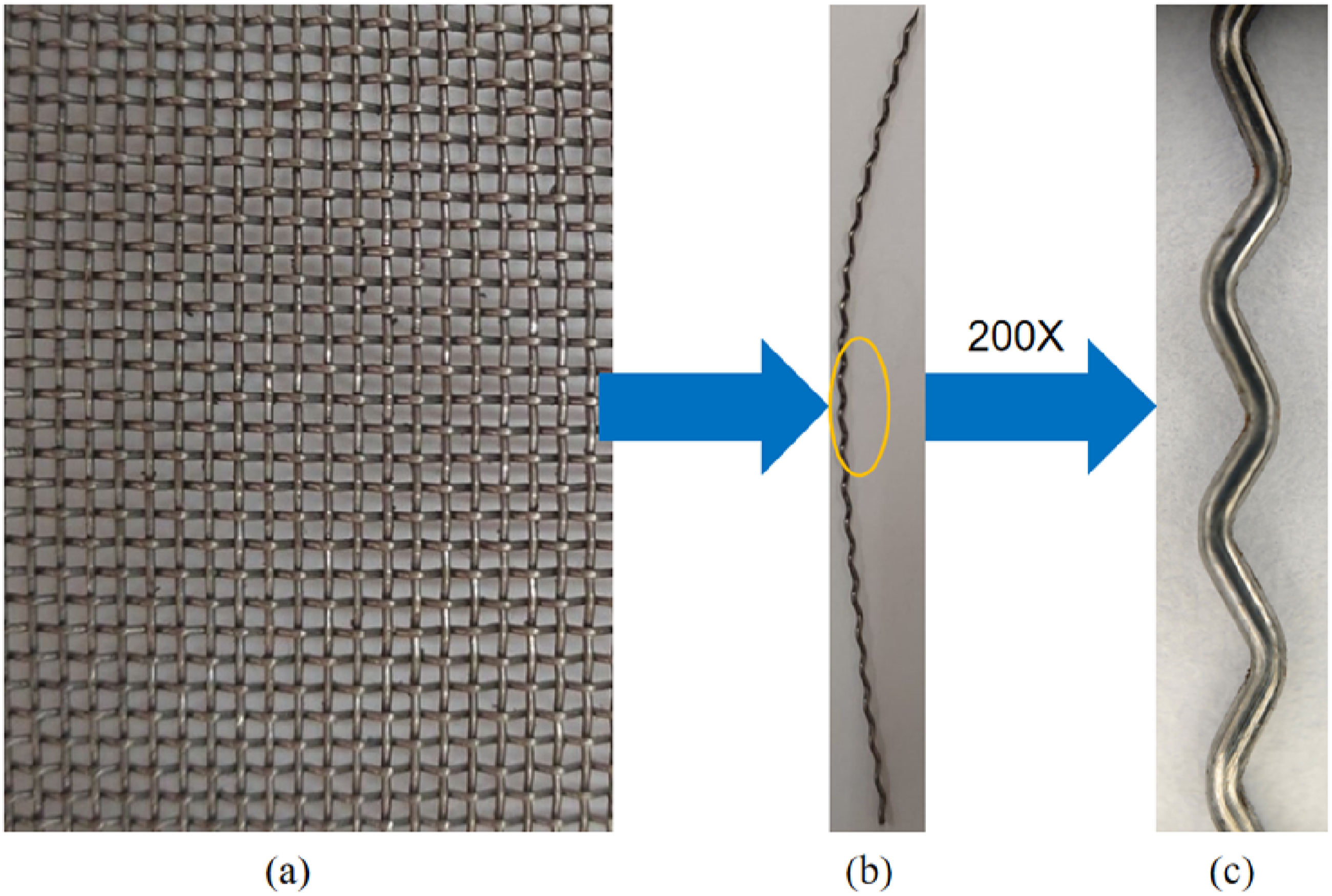
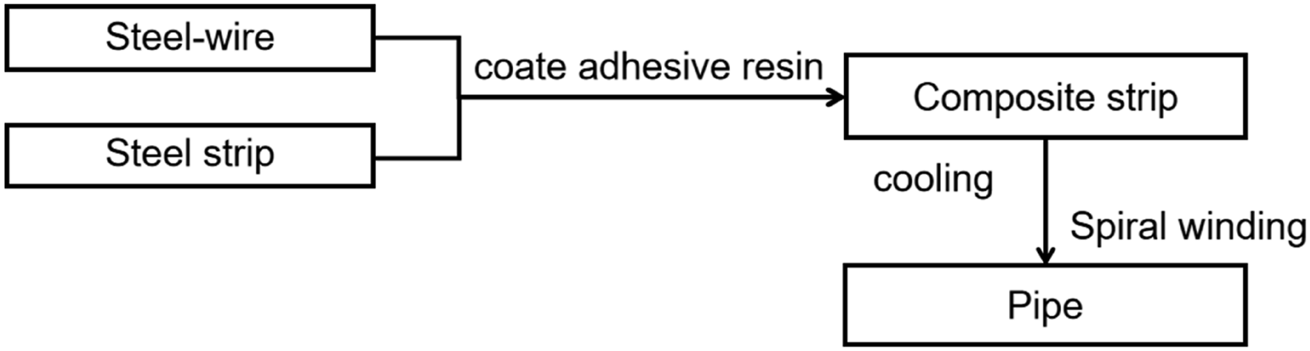
In the second stage, the steel-wire mesh and the steel strips are fed into a mold from the right side to be coated with adhesive resin, as shown in Figure 4(a). The mold has two groups of channels at different orientations with different shapes, including flat shape and rectangular shape. The flat-shape channel is in the upper part of the mold for the steel-wire mesh, and the rectangular-shape channels are in the lower part of the mold for the steel strips. In this stage, the molten adhesive resin is extruded and wrapped around the preheated steel-wire mesh and steel strips through the mold. In the next step, the steel-wire mesh and steel strips coated with adhesive resin enter the composite device from the right side as shown in Figure 4(b), where the extrusion molding is performed to wrap around the steel-wire mesh and the steel strips with HDPE. A new composite strip comes out from the left side of the extrusion mold integrating the steel-wire mesh and the steel strips. As shown in Figure 4(c), the steel strips on the production line are perpendicular to the steel-wire mesh in the composite strip. To ensure that the material of the continuous composite strip hardens and retains its shape, the composite strip is cooled by a cooling device after coming out of the extrusion mold. After being cooled, the composite strip is subjected to a series of quality checks, including dimensional measurement, visual inspection and pressure testing, to ensure that the product meets the specified standards. Strip composite device. (a) Feed raw material into the mold, (b) Coating bond resin, (c) Composite strip.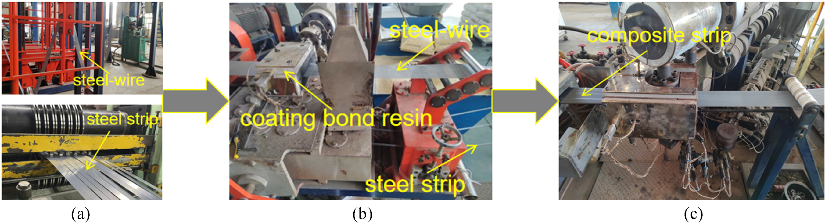
In the final step of the production process, the composite strip is continuously sent into a rotating mold. In this process, the composite strip is enwound in a spiral path to form a tubular structure. As show in Figure 5(a). In order to ensure the integrity and strength of the structure, the HDPE parts adjacent to the edges of each segment of the composite strip are connected by a fusion welding process. Specifically, these HDPE areas are designed to overlap with each other and enable 360-degree fusion welding during winding, as show in Figure 5(b), ensuring a strong bond between adjacent strips. This process not only ensures the integrity of the pipe, but also enhances its mechanical properties and tightness, resulting in the final product MRSPCP. As shown in Figure 5(c), the spiral structure and fusion welding details of MRSPCP are shown. The entire production process is summarized in Figure 6. Fusion welding device. (a) Winding forming, (b) Overlaping position, (c) MRSPCP. Schematic diagram of production flow.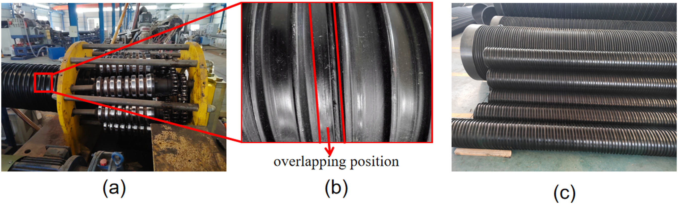
Experimental Study
Uniaxial Tensile Test
In this experiment, uniaxial tensile test of HDPE, steel-wire and steel strip were carried out with the LISHI universal testing machine (provided by Shanghai LISHI Instrument Testing Co., LTD). The testing machine could be set for tensile test at different strain rates and the test data of the whole process could be obtained. The extensometer used with the test machine was the type of SANJ YSJ50 (supplied by the Central Iron and Steel Institute, located in Beijing, China), and it could measure uniaxial tensile strain up to 50%. During testing, the test machine was controlled by the LISHI test software.
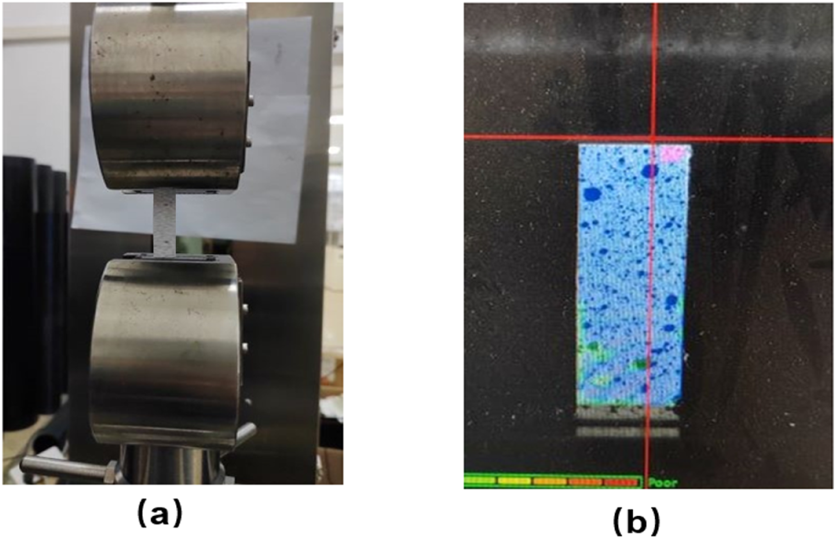
Due to the small diameter of the steel-wire sample, it was not suitable for the extensometer measurement. In this test, a 2D Digital Image Correlation system (VIC-2D, supplied by Correlated Solutions, Inc. Location South Carolina, the USA) was employed to monitor the tensile process and extract the strain data. The VIC-2D test system was mainly composed of hardware (CCD camera, light source, control host) and software (VIC-Snap image acquisition software, VIC-2D V6 analysis image processing software). First of all, a suitable size of white plastic sheet was cut and painted to make black speckles, as shown in Figure 7. Speckle was for DIC equipment to accurately obtain image reference points. Images were collected by CCD camera and then discretization digital images were stored in computer through A/D converter, so speckle should be clear and uniform. After that, the plastic sheet with speckle was glued on the steel-wire sample with hot melt adhesive (See Figure 7). A certain distance was maintained between the two pieces, and the DIC light source and focal length were adjusted to make the captured images clear and not overexposed, so as to facilitate subsequent computer processing of data. It was similar for the tensile test of steel strip samples, but because the steel strip itself had a certain width, it was possible to paint the steel strip samples directly to make speckle, as shown in Figure 8. It was worth mentioning that the steel strip should be polished before spraying speckle, and the impurities on the surface of the steel strip should be cleaned with fine sandpaper. Uniaxial tensile of steel-wire. Steel strip clamped sample and VIC-Snap images.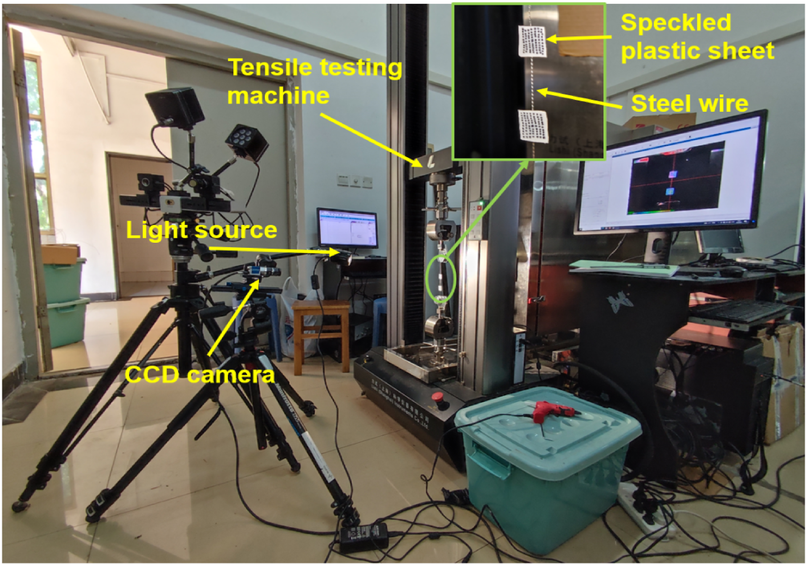
The loading rate of the LISHI tensile testing machine was set at 1 mm/min and the image acquisition frequency of the DIC equipment was 2s per chart. At the beginning of the test, the stretching of the testing machine and DIC shooting were started simultaneously by a synchronized cable. Finally, the test was terminated when the steel-wire and steel strip broke, and the collected data was extracted and sorted.
As the steel wire is curly, the obtained uniaxial tensile test data of the steel wire can’t reflect its true stress-strain relationship, because the steel wire will be stretched and the angle between adjacent segments of the steel wire must change. It leads to that the recorded displacement data can’t directly deduce the strain data of the steel wire. The method to characterize the tensile properties of the steel wire is stated in the next section in detail.
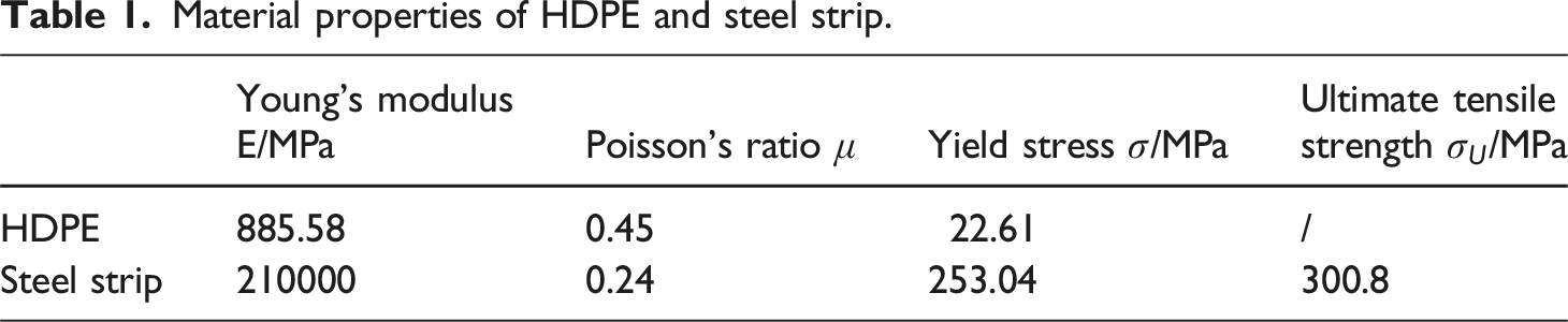
Figure 9 shows the true stress-strain curve converted from the uniaxial tensile curve of HDPE and steel strip. Both HDPE and steel strip exhibit significant nonlinear mechanical behavior. Since HDPE does not break, its ultimate stress is difficult to obtain. A bilinear model is constructed to represent the mechanical behavior of the HDPE in the following finite element analysis. Tangential fitting is conducted at the tensile curve of HDPE within elastic stage and plastic stage respectively, to get the elastic modulus and the yield strength. For the true stress-strain curve of the steel strip, it can be found that the steel strip has obvious yield point and fracture failure point, so its yield stress and ultimate tensile strength can be intuitively obtained, and the tangent line can be made in the elastic stage of the steel strip. The slope of the dark blue tangent line in Figure 9(a) and (b) is Young’s modulus, and the intersection point between the blue green tangent line and the dark blue tangent line is the yield point of HDPE in Figure 9(a). The material parameters of the HDPE and steel strip are listed in Table 1 respectively. Uniaxial tensile curves of the composition. (a) HDPE, (b) steel strip. Material properties of HDPE and steel strip.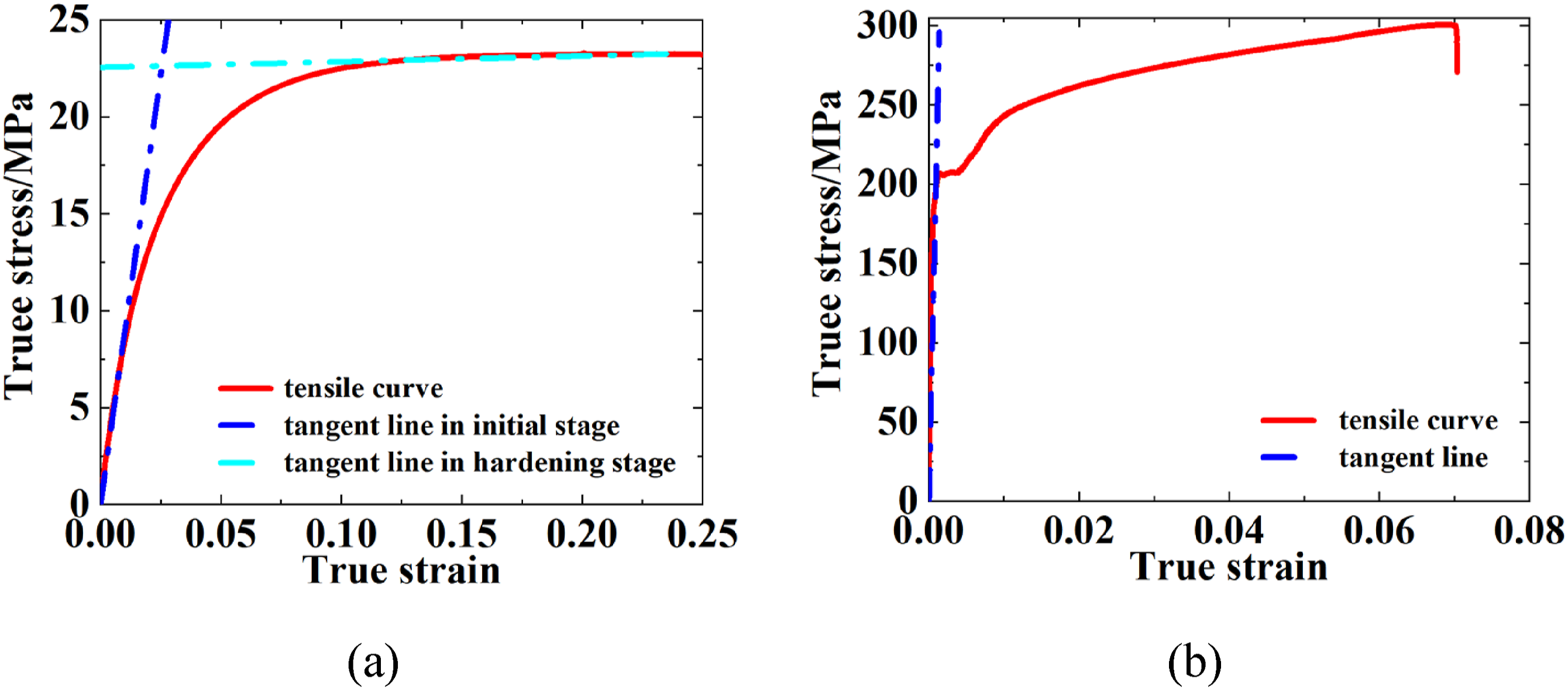
MRSPCP Burst Test
Burst test of the MRSPCP was performed to assess its mechanical performance, and the failure criterion of the MRSPCP was expected to obtain via observing the failure specimen of the pipe and analysis after the test. According to the Chinese standard GB/T 6111-2018,
37
the short-term burst test of DN315 PN1.0 MRSPCP was carried out, and three MRSPCP specimens of the same specification were employed in the tests to verify the finite element model. The equipment used in the burst test was a hydrostatic testing machine of HTM series type A, produced by Shenzhen Wanyi Test Equipment Co., LTD. Figure 10 shows schematic diagram of the burst test device. The A-type fixture was adopted in the test, which was recommended by GB/T 6111-2018
37
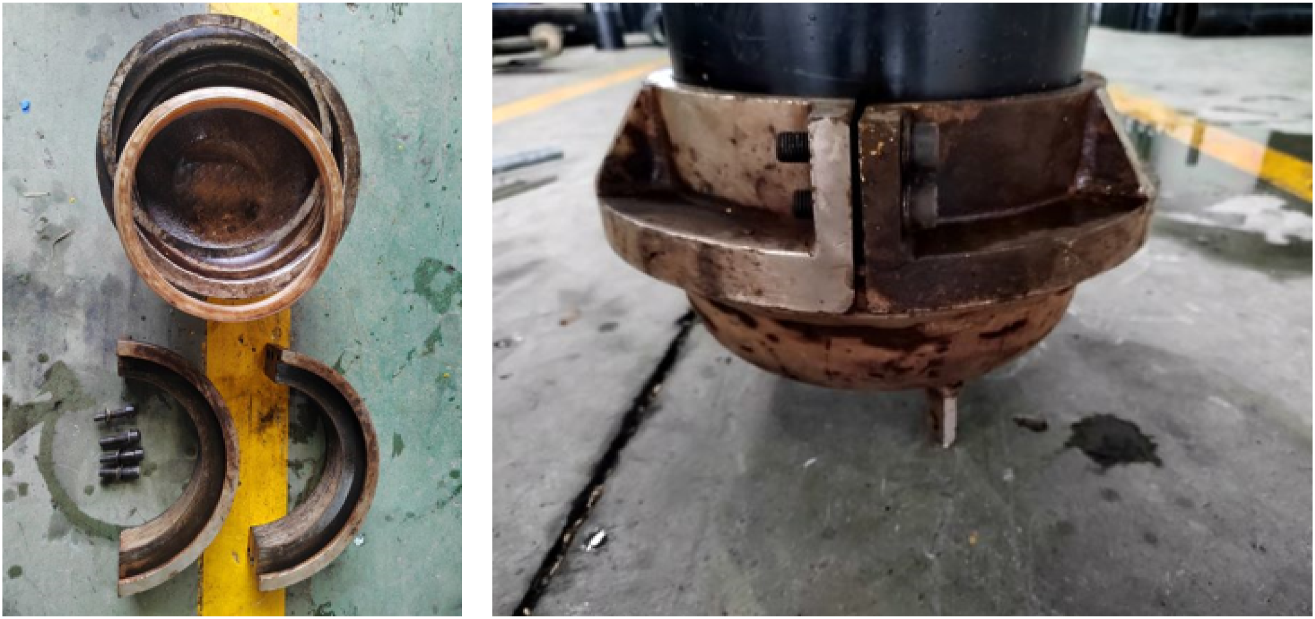
(See Figure 11). Schematic diagram of burst test device. MRSPCP burst test head.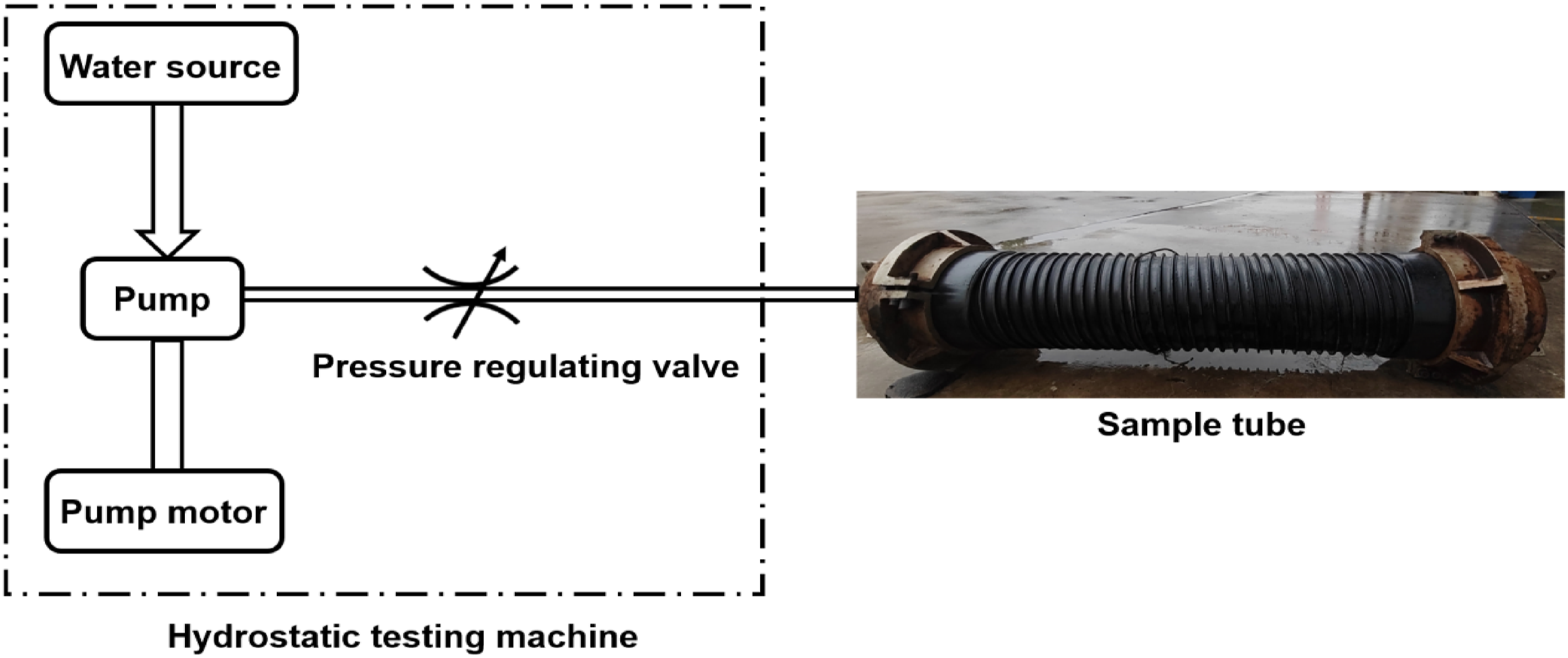
In order to ensure the rupture of the pipe during the test, determination of the appropriate test pressure was crucial. According to the Chinese standard GB/T 6111-2018, 37 the burst pressure was required to be not less than three times the nominal pressure, so the minimum pressure for the PN1.0 MRSPCP burst test was set to 3 MPa. The flow settings of the testing machine were intelligently managed by a test-controlled system. In the test, just the maximum pressure needed to be input, and the system could automatically calibrate the flow. As the test began, the jet pump in the test system started, and the internal pressure initially rose sharply, then the internal pressure increased more gradually until a sudden failure occurred.
The test results show that the failure characteristics of the steel pipe at the overlapping interface of the composite strip are fracture along the winding direction of the composite strip and fracture of the steel-wire mesh. Although the specific failure sequence of overlaps and wire mesh is difficult to determine directly from the test, reasonable inferences can be made through subsequent analysis. The failure does not originate solely from the fusion welding area itself but occurs on the composite strip adjacent to the fusion welding area, which is attributed to the stress concentration caused by fusion welding. In theory, if the fusion welding strength is insufficient, the fracture process should not immediately destroy the wire mesh in the continuous composite strip. However, all MRSPCP (metal-reinforced plastic composite pipe) samples showed fracture of the steel-wire mesh, suggesting that the failure of the wire mesh may be closely related to stress concentration in the fusion welding area, and may even occur before or at the same time as the fracture of the overlapping portion. As shown in Figure 12, the enlarged image clearly identifies the starting position of the pipe failure. Therefore, when determining the failure criteria of MRSPCP, in addition to evaluating the condition of the overlapping part, the impact of stress concentration on the composite strip should be deeply considered. By observing the failure sample, we noticed that only one steel strip showed signs of fracture in the three tests, as shown in Figure 12(c); In the other two tests, the strips remained intact. This suggests that the fracture of the steel-wire may be caused by a concentration of stress near the fusion welding area, resulting in an early release of local strain energy, while the steel strip, due to its structural characteristics, may better disperse the stress and thus not break. Under ideal design and manufacturing conditions, when MRSPCP fails, the steel wire and steel strip should break almost simultaneously to ensure the consistency of the structure. Results after bursting effect. (a) Axial fracture, (b) Overlap fracture, (c) Circumferential fracture.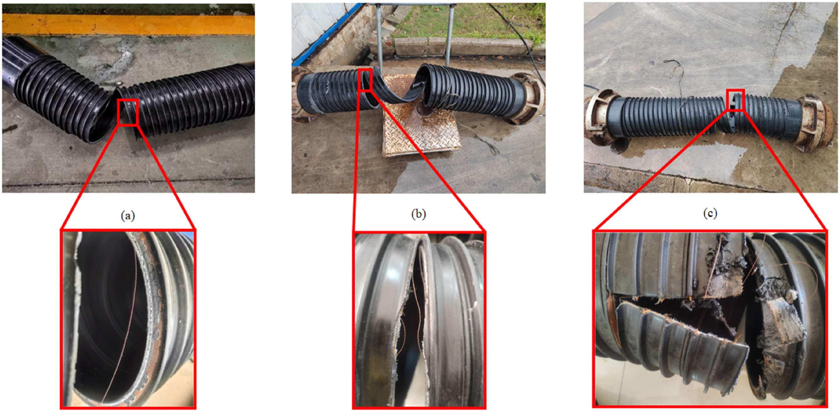
Theoretical Calculation
Simplification of Steel-Wire Model
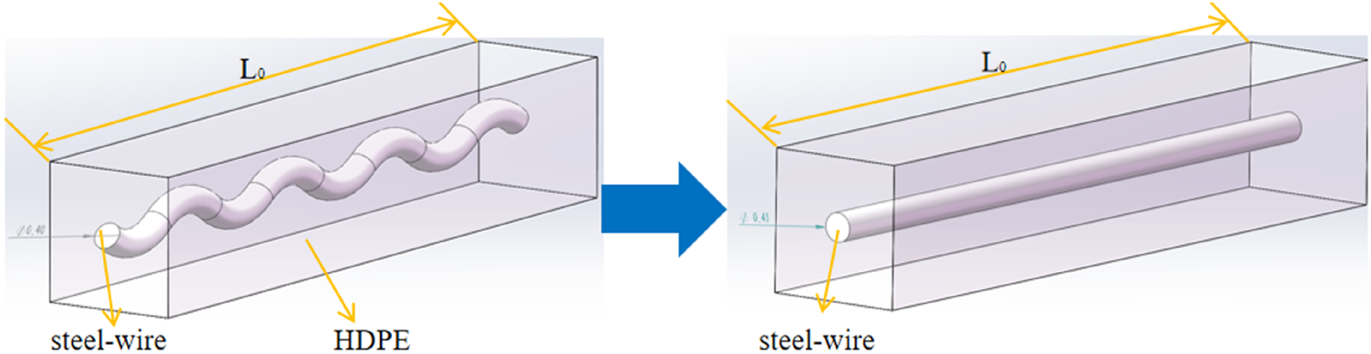
As mentioned above, it is difficult to obtain the stress-strain relationship of the curly steel-wire directly from the uniaxial tensile test, because the straightening of the curly steel-wire severely affects the measurement of the strain during the uniaxial tensile process (See Figure 3). To get an available stress-strain relationship of the steel-wire for the analysis of MRSPCP, a simplification is conducted to consider the curly steel-wire as a straight one, in the premise of keeping volume fraction of the steel-wire in the composite strip unchanged, as shown in Figure 13. After this simplification, the mechanical parameters of the straight steel-wire are still unknown. In this paper, a bilinear model is used to characterize the tensile properties of steel wire, and the stress-strain relationship of steel-wire is simplified into two linear parts to describe the elastic and plastic behavior of the material.38,39 The three main parameters of the bilinear model are the elastic modulus, the yield strength, and the strain-hardening modulus, which respectively represent the stiffness of the material, the stress level at which the plastic deformation begins, and the way the stress changing with the strain after yielding. Then, referring to the parameter inverse identification method,40–42 finite element modelling is employed to help determine the mechanical parameters of the simplified straight steel wire by presetting model parameters and making the simulated tensile curve consistent with the experimental one. Steel-wire segment length measurement.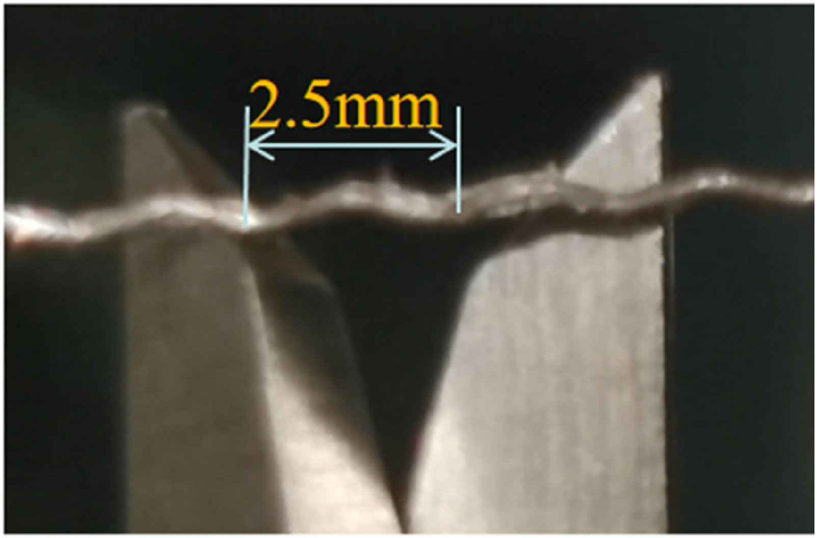
The presetting parameters ensuring the consistency between the simulated curve and the test one can be suitable to represent the mechanical properties of the steel-wire. Specific implementation steps of the simplification are as follows. The first step is to determine the dimensions of the simplified straight steel wire. Owing to a smart phone combined with a magnifying lens, the actual dimensions of the curly steel wire can be measured. As shown in Figure 10, the radius of the steel wire is 0.2 mm. The cycle length of the periodic structure of the curly steel-wire segment is 2 mm, with peaks and troughs of 0.2 mm.
For convenience of volume fraction calculation, 10 cycle lengths of the periodic structure are considered to determine the transferred dimensions of the simplified straight steel wire. The linear distance between the two ends of the wire is 25 mm, which must be shorter than the stretched length of the curly steel wire. To keep the volume fraction of the steel-wire in the HDPE matrix unchanged, as shown in Figure 14, the radius of the simplified straight steel wire has to be larger than that of the curly steel wire. According to equation (1), the effective radius of the steel-wire can be calculated to 0.205 mm. Simplified schematic diagram of steel-wire.

Further, the mechanical property of the steel-wire is assumed to follow a bilinear elastoplastic model, as shown in Figure 14, but the necessary parameters of the model are unknown, including the elastic modulus, yield strength, strain-hardening modulus. The ultimate strength can be calculated out via the test data of the uniaxial tensile test of curly steel-wire. The method to determine the three unknown parameters is to priorly preset the parameters in the finite element model of the straight steel-wire and implement the simulation of uniaxial tensile loading via ABAQUS.
43
After the simulation result comes out, the simulated tensile curve of tensile force and displacement should be checked whether it is consistent with the test one. If not, the three presetting parameters should be changed according to some algorithm such as pattern search method, until the trend of the simulated curve is similar to the test one. The whole process is like the inverse parameter identification methodology in many earlier publications.
44
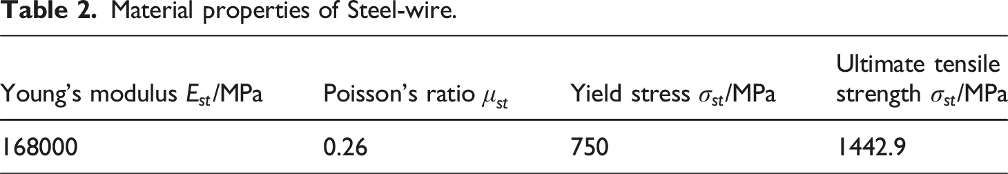
The comparison is displayed in Figure 15(a) between the test curve and the simulated one in terms of the force- displacement relationship after many rounds of iterations, which indicates that the simulated curve is quite consistent with the test one and the inverse parameter identification method works well. The stress-strain curve of the simplified straight steel-wire is shown in Figure 15(b), and the material parameters of the simplified straight steel-wire are obtained in Table 2. Tensile curve of steel-wire. (a) Force-displacement, (b) stress-strain. Material properties of Steel-wire.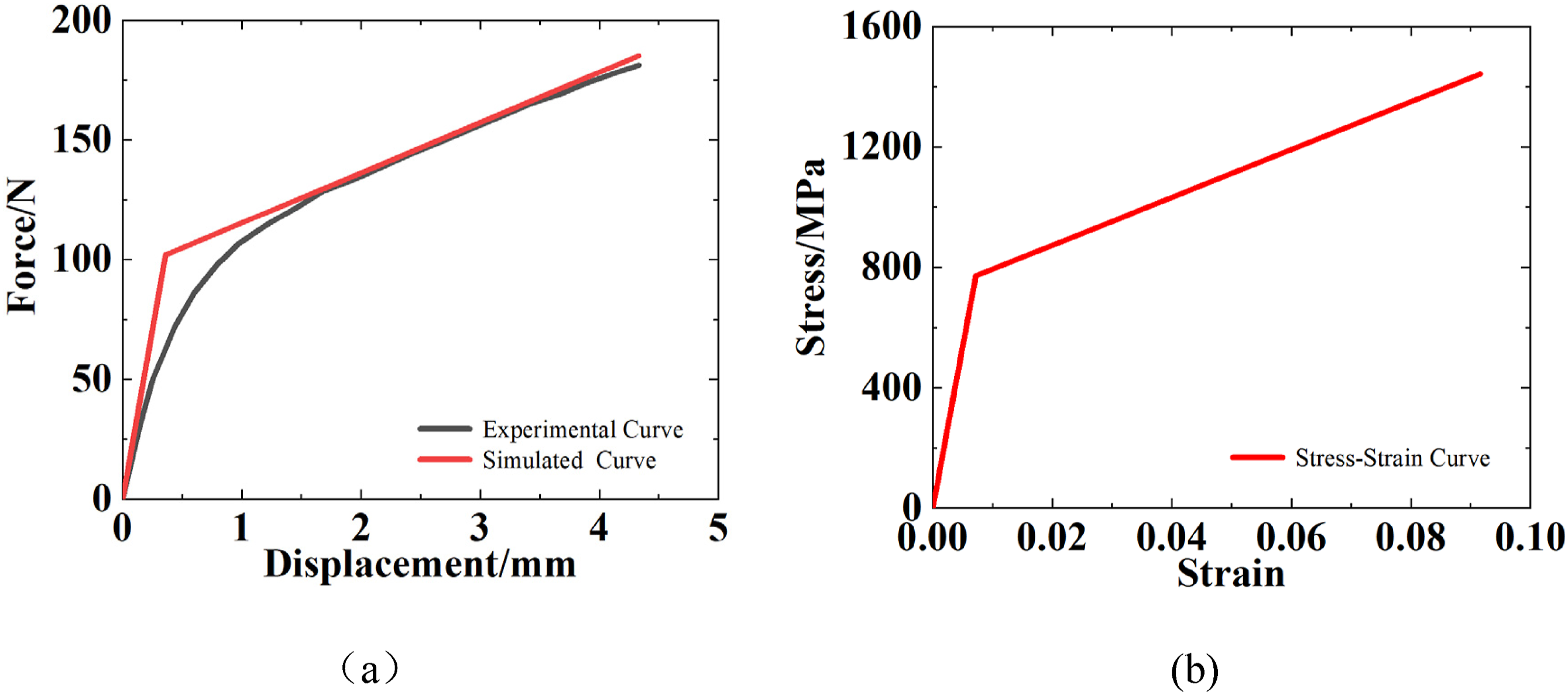
Theoretical Analysis
MRSPCP is composed of HDPE, steel-wire mesh and steel strip, and its ultimate strength can be regarded as the superposition of these three parts. Considering the possible structural failure modes in pressure vessel and pipes under internal pressure, 45 it is assumed that the MRSPCP has two structural failure modes theoretically, including the structural failure along the hoop direction and the axial direction, respectively.
According to the static equilibrium, the force caused by the internal pressure should be in balance with resultant force caused by the stress in the pipe wall of the MRSPCP along both the hoop direction and the axial direction. Thus, by calculating the hoop and axial forces of HDPE, steel strip and steel wire in the pipe, as well as the force caused by the internal pressure, the equations of static equilibrium can be set up along both the hoop direction and the axial direction. Then substituting the material ultimate strength of the steel wire, the steel strip and the HDPE into the corresponding stress in the equations of static equilibrium, the internal pressure corresponding to the structural failure of the MRSPCP can be obtained. From the perspective of the possible failure modes, there are two calculation results of the failure pressure corresponding to the pipe failure along the hoop direction and along the axial direction. In reality, there must be only one result of the failure pressure, so the minimum value of the two results should be the short-term burst pressure of the MRSPCP.
46
The calculation process is listed in detail as below. The structural parameters of MRSPCP components are indicated in Figure 16, and the specific meanings of each parameter are listed in the table on the first page. MRSPCP component structure parameters.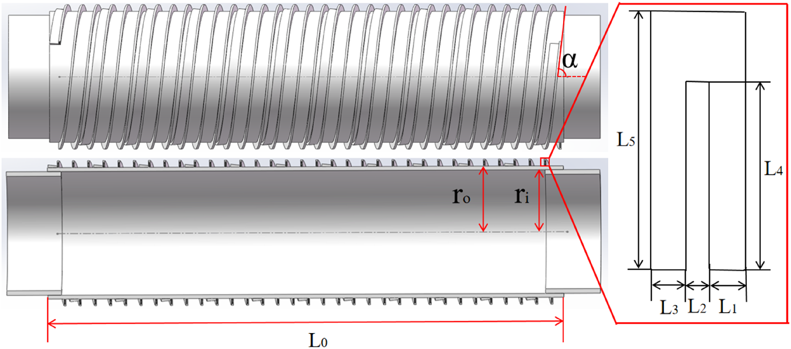
MRSPCP Hoop Load Balance
1. Hoop force of axial steel-wire: 2. Hoop force of hoop steel-wire: 3. Steel strip ring force: 4. The circular force of HDPE: 5. Pipe hoop force consists of the force in steel wires, steel strips and the HDPE: 6. Pipe hoop burst pressure:


MRSPCP Axial Load Balance
1. Axial component of hoop steel-wire: 2. Axial steel-wire axial component: 3. Steel strip axial force: 4. HDPE axial force: 5. Pipe axial force consists of the force in steel wires, steel strips and the HDPE: 6. Pipe axial burst pressure: 7. Theoretical calculation pressure of MRSPCP failure:


Finite Element Modelling
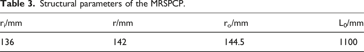
Structural parameters of the MRSPCP.
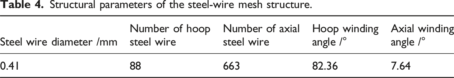
Structural parameters of the steel-wire mesh structure.
Structural parameters of the HDPE structure outside steel strip.
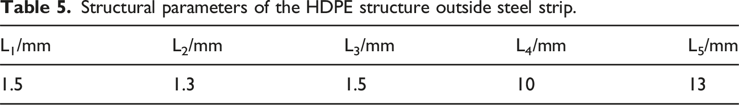
MRSPCP component model. (a) Steel-wire mesh, (b) Steel strip and outer HDPE, (c) Overall model of MRSPCP.
According to the structure of the steel-wire mesh, the axial steel wire and the hoop steel-wire were perpendicular to each other at their intersection points. In the MRSPCP model, the axial steel wire in the continuous composite strip was shorter than the hoop steel wire, which spread over the whole pipe along the spiral winding angle and bonded by HDPE. The axial steel wire was modelled as discontinuous parts, and the length of each discontinuous part was equal to the width of the continuous composite strip. To facilitate 3D modelling, the overlapping segment of winding continuous composite strip was modeled separately from the main body of the MRSPCP model.
For the convenience of generating mesh in the ABAQUS, auxiliary planes were set to divide the pipe model into many parts, as shown in Figure 17. Generally, in the hydrostatic test, to avoid the sealing failure of the pipe caused by axial loading, researchers usually connect the tie bars to the ends of the pipe, and the axial loading is undertaken by the tie bars instead of the pipe.
48
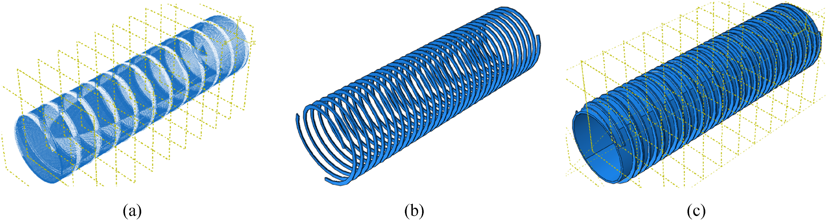
However, in the hydrostatic test of this paper, a rubber ring seal was used to ensure the sealing performance of the head, so tie bars was not employed in this test. In addition, in the practical application, the MRSPCP will undertake the axial loading and the hoop loading simultaneously , so the axial loading is not something that needs to be avoided at all costs. Accordingly, in the finite element model, the boundary condition of displacement and the equivalent axial load were applied to the ends of the MRSPCP. To facilitate the application of boundary condition and load, a short pipe defined by a rigid body was generated and attached to the internal surface of each MRSPCP end, as shown in Figure 18. The internal pressure of 4 MPa was applied directly on the internal surface of the MRSPCP model. All degrees of freedom of one end except the radial displacement in the MRSPCP model should be constrained, and the other one should be applied an equivalent axial load of internal pressure for the burst failure analysis to represent the closed-end condition. To avoid extreme stress concentration of the ends of the pipe model, the boundary condition of the displacement and the equivalent axial load were applied on the rigid short pipe, instead of the MRSPCP model. The equivalent axial load was imposed on the outer surface of the pipe end as surface traction, and the surface traction corresponding to the internal pressure was calculated as below.
49
MRSPCP load conditions. (a) Surface traction and One-end complete constraint, (b) Pipe internal pressure.
The interaction between the steel strip and the HDPE matrix was defined by tie interaction in ABAQUS, as well as the interaction between the steel strip and the main body of the MRSPCP. C3D8R element was used for all parts except steel-wire, and the steel-wire was represented by T3D2 element. The main configurations of the high-performance server used in this study were as follows: Intel(R) Xeon(R) Platinum 8375C CPU with four processors (each at 2.9 GHz) and 256 GB of memory. The server ran Windows 10, 64-bit OS, and the hard disk capacity was 4 TB.
Results and Discussion
Structural Failure Analysis of MRSPCP
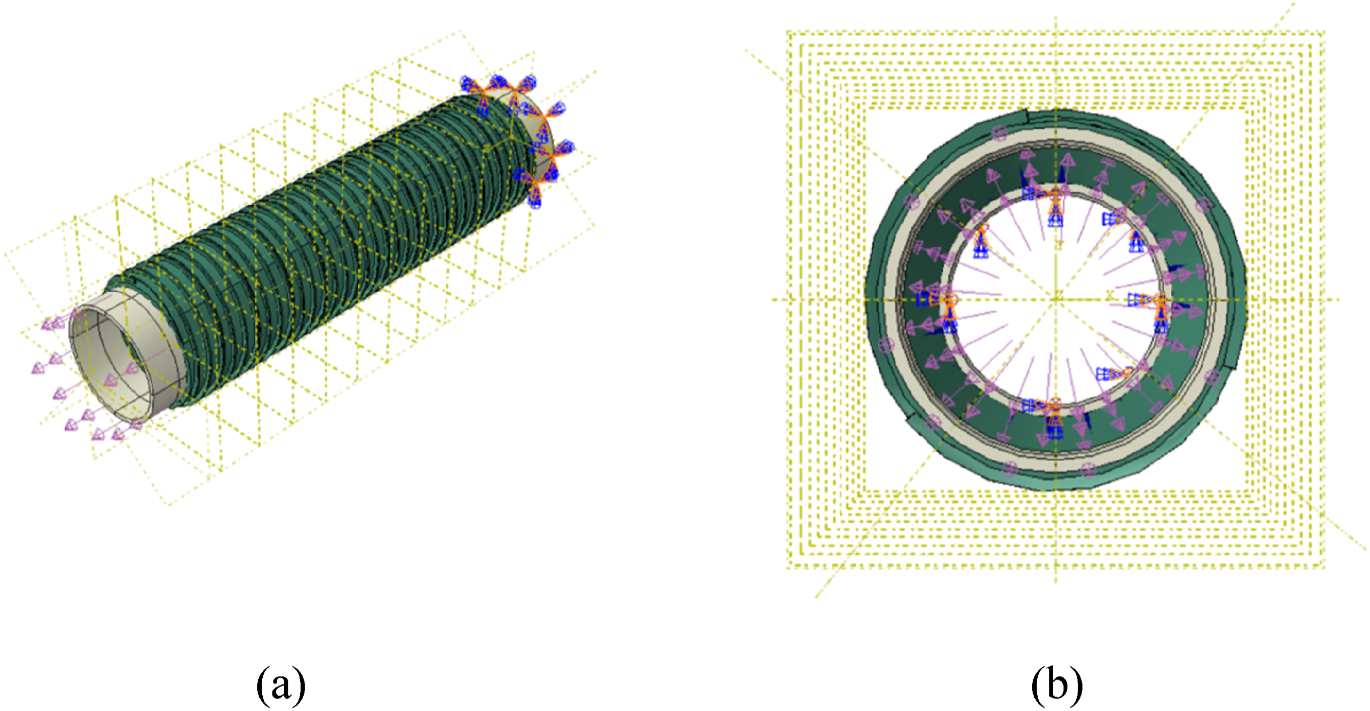
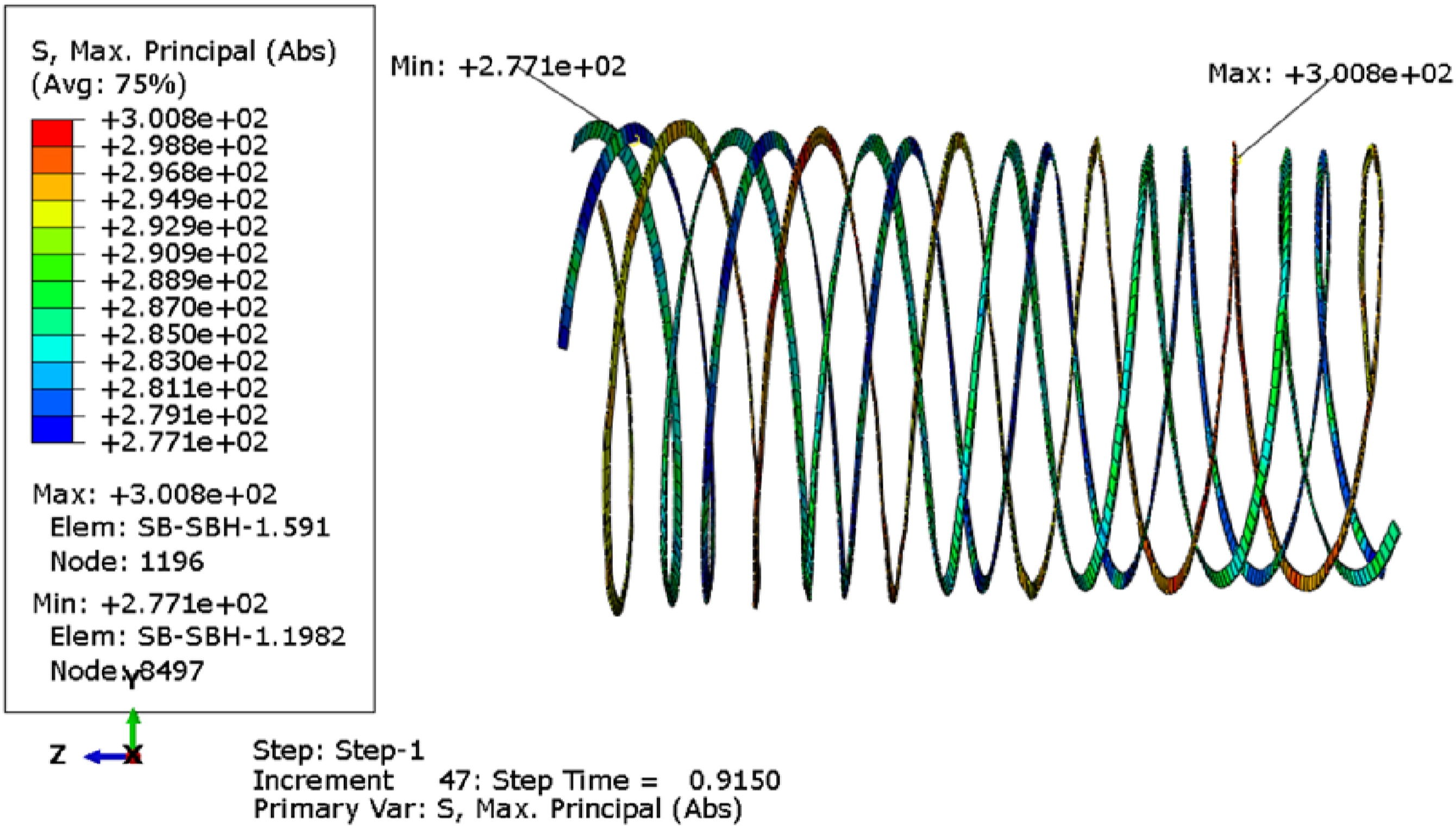
As mentioned above in the analysis on the burst test result, the failure criterion of the MRSPCP is considered to be the breakage of steel wires. Thus, to check whether the MRSPCP has failed, the stress distribution of different components should be demonstrated. As shown in Figures 19–21, the max principal stress distribution of the steel wires, the steel strips and the HDPE are illustrated. When the step time is equal to 0.9150, the maximum principal stress of the steel wires just exceeds the ultimate strength a little bit, so at the current step time the MRSPCP can be considered to fail. In addition, the stress contour plot shows that in the overlapping part of the composite strip, the axial steel wire and the circumferential steel wire have most green and blue areas, which indicates that the load on this part of the steel wire is small (as shown in Figure 19(c), the overlapping section of steel wire is locally enlarged and marked). This is because the overlapping of the composite strip increases the thickness and stiffness of the pipe at the overlapping region and reduces the deformation of the local HDPE and steel wire mesh. In addition, the number of steel wire in the overlapping region is also increased, so the stress level of the steel wires in that region is also reduced. Accordingly, on the stress contour plot, the stress of the steel wire in the overlapping region is lower. Contour plot of Mises stress in steel wires when the MRSPCP fails: (a) hoop steel wires, (b) axial steel wires, (c) all steel wires. Contour plot of Mises stress in steel strips when the MRSPCP fails. Contour plot of Mises stress and equivalent plastic strain in the HDPE when the MRSPCP fails: (a) Mises stress distribution, (b) Equivalent plastic strain distribution.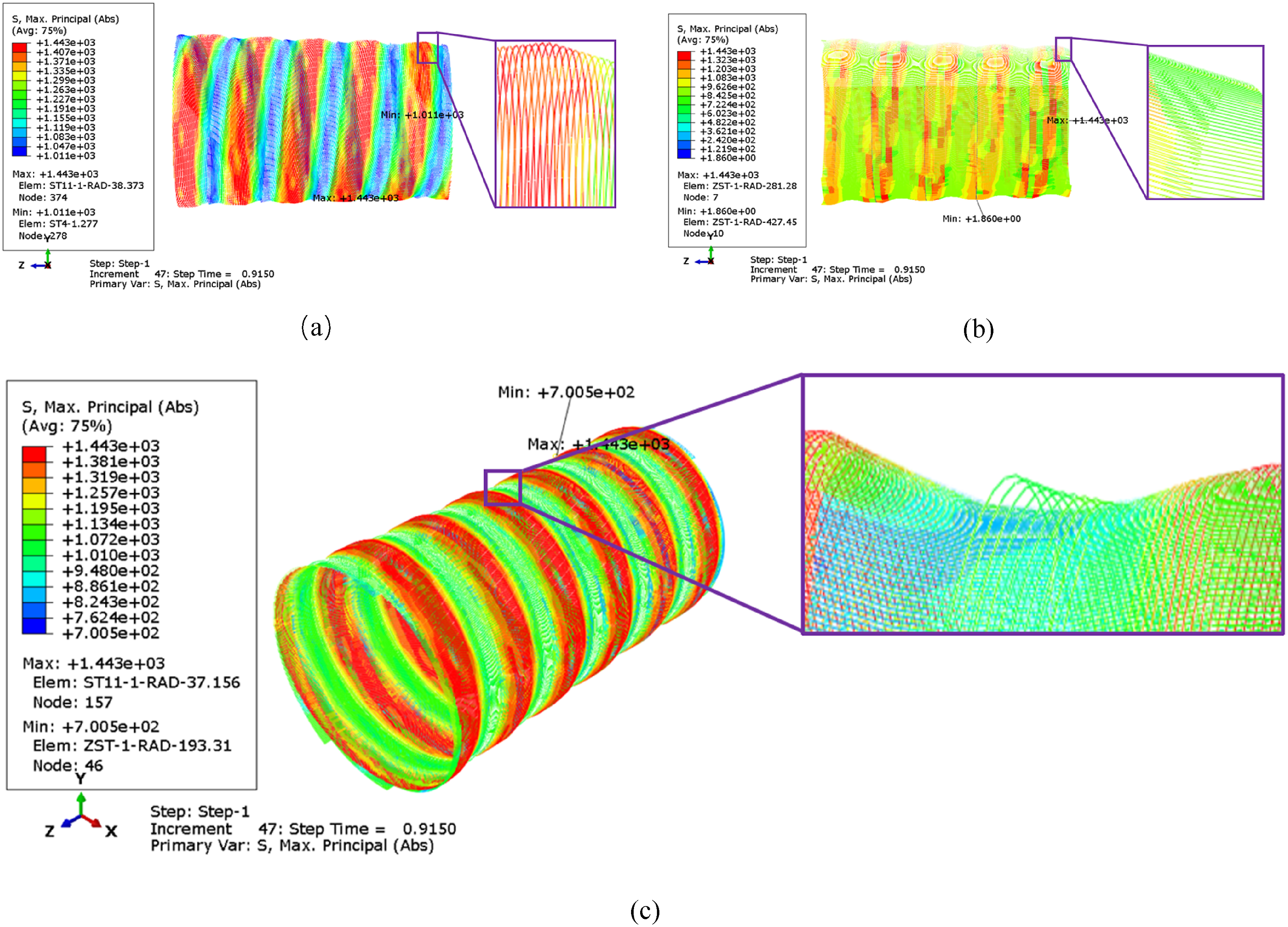
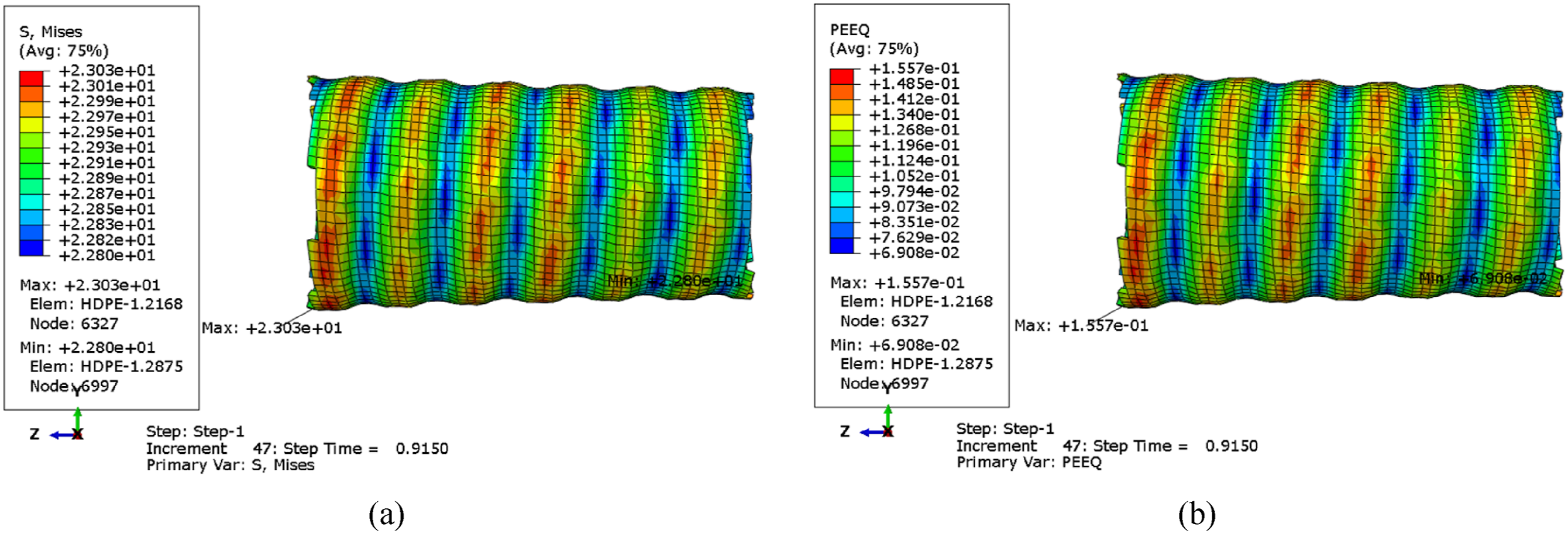
Then the stress distribution of the steel strips is shown in Figure 20, it can be seen that at the same step time of 0.9150 the maximum principal stress of the steel strips is also nearly equal to its ultimate strength. To avoid the influence of the evitable stress concentration around the MRSPCP ends on the stress contour plot, the elements of the steel strips in the middle segment of the MRSPCP are selected, and the uniform stress distribution can be found in the steel strips, due to these steel strips continuously winding along the pipe. In the end, the distribution of the Mises stress and the equivalent plastic strain in the HDPE matrix is seen in Figure 21(a) and (b). Figure 21(a) shows that the Mises stress in the HDPE is relatively high, but the equivalent plastic strain of the HDPE indicates that the HDPE is far from its failure, as the elongation after break for the typical polymer materials such as HDPE can be over 500%.50–52 In addition, the contour plot showed that the mises stress distribution of HDPE on the same level looks continuous band around the pipe, as well as the PEEQ distribution. This was also determined by the winding structure of MRSPCP. The blue band representing the low level Mises stress of HDPE was caused by the overlapping of the composite strip.
The FEM results show that in the MRSPCP finite element model the steel strip and steel wire almost fail at the same time, which agrees well with the test result to a great extent. The FEM results indicate that both the steel wires and the steel strips are like to play significant roles on the load bearing capacity of the MRSPCP. In the burst tests of the MRSPCP, steel wires of all pipe specimens are found to fail, and the steel strips are found to fail in only one specimen. As for the MRSPCP under internal pressure, no matter which one firstly fail among the steel wires and the steel strips, the left one not instantly failing can not undertake the load caused by the internal pressure by itself. Whether the left one will break or not mainly depends on the degree of severity of the pre-existing defects in the left one and the amount of the strain energy released at the burst moment of the MRSPCP specimen. Or rather, for the MRSPCP specimens which have been used for the burst tests, if the pre-existing defects in the steel wires are severe, the steel strips might not be broken. Or if some parts of the MRSPCP specimen around the breaking steel wires instantly crack, then large amount of the strain energy is already released, then the steel strips won’t break either. Combining with the FEM results and the stress distribution in various components, it is reasonable that the failure criterion of the MRSPCP is considered as the breakage of the steel wire.
Since the steel wires and the steel strips are the main load-bearing components of MRSPCP, once the steel wires and the steel strips fail, the load of HDPE will rise sharply due to load transformation. Although the ductility of HDPE is excellent, its ultimate strength is quite low and the HDPE can’t work alone without the support of the steel wires and the steel strips. The HDPE has to fail immediately as expected in the failure of the MRSPSP. 47 The FEM result also indicates that the HDPE will be the last component to reach its ultimate strength.
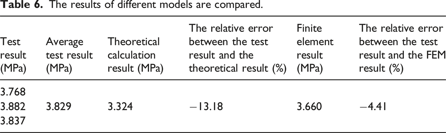
The results of different models are compared.
Load Analysis of MRSPCP Components
In order to further study the bearing capacity of each component in the model, this study adopts the hoop mechanical response to characterize the mechanical performance, 14 and compares the force proportion of each component in the total hoop force in the MRSPCP wall.
The formula for calculating the circular force Fpe of HDPE is as follows:
The expression Fst of the hoop force of steel-wire is:
The expression Fsb of the hoop force of steel strip is:
The load proportions of different components in the MRSPCP subject to the burst pressure are shown in Figure 22(a), HDPE can bear about 42.9% of the load when it is subjected to hoop load, while steel strip and steel-wire mesh share 57.1% of the load. Compared with traditional HDPE pipe, the carrying capacity of MRSPCP is greatly improved. This significant improvement is due to the reinforced structure of the embedded steel-wire mesh and steel strip, which makes the pipe more resistant to hoop stresses. Comparison of load in all MRSPCP components. (a) Circumferential load, (b) component load proportions.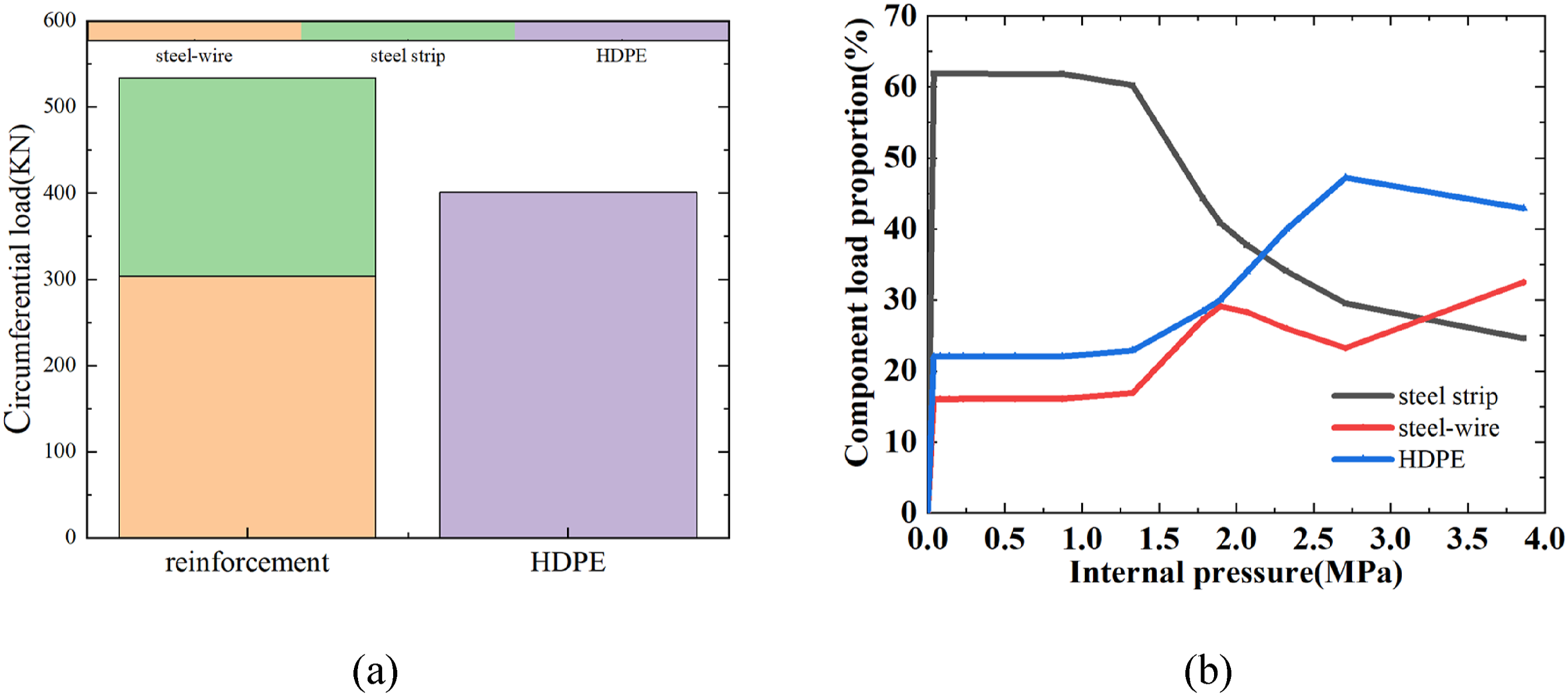
The plots of stress contour of different components in MRSPCP under different internal pressures.
When the internal pressure reaches about 2.0 MPa, the steel wire starts to deform plastically, as shown in the second row in Table 7. Thus, the red curve in Figure 22(b) become falling as the growth rate of the steel wire stress with its deformation decreases when the steel wire enters its strain-hardening stage. Afterwards, the internal pressure continues to rise to about 2.7 MPa, the Mises stress of the HDPE approach its yield strength, as shown in the third row of Table 7. Similar to the change of the red curve representing the steel wire, the blue curve also starts to decline, as the dramatic decrease of the growth rate of the HDPE stress with the strain after yielding determines the growth rate of the blue curve with the internal pressure at this moment.
In the later period of the loading process, because the stress level of the steel wire is quite high, as well as its strain-hardening modulus, the steel wire possesses the largest scope of stress increase, and the red curve can gradually increase, while the stress-strain curves of the steel strip and the HDPE are close to the ideal elastic-plastic curve after yielding, so the black and blue curves in Figure 22(b) are constantly declining.
Figure 23 demonstrates the variety of equivalent plastic strain (PEEQ) in different components with the internal pressure. It can be seen that the steel strip is the first to deform plastically, and the steel wire is the second, in the end the HDPE yields. This is because the HDPE deforms coordinatively with the steel wires and steel strip, and the yield strain of the HDPE is much larger than the steel wires and steel strip. Curve of MRSPCP loading PEEQ with internal pressure.
Effect of Steel-Wire Diameter
In the load analysis of different components in the MRSPCP mentioned above, it is known that the steel wires have a great influence on the load bearing capacity of the MRSPCP, so the diameter of the steel wire certainly plays an important role on the performance of the MRSPCP. Thus, in this section, the finite element models of the MRSPCP with different diameters, including 0,0.2, 0.4, 0.6, 0.8 and 1.0 mm, are established to investigate the variation of the mechanical performance of the MRSPCP with the steel-wire diameters.
Figure 24 shows the effect of different steel-wire diameters on the failure pressure of the MRSPCP. It can be seen that the failure pressure of the MRSPCP increases monotonously with the internal pressure, and this is consistent with the variation of the steel-wire volume fraction with the diameter. Initially, when the diameter of the steel wire is 0, the MRSPCP becomes a plastic pipe reinforced only by the steel strips, and its failure pressure is about 2.7 MPa. When the steel-wire diameter increases to 0.2 mm, the failure pressure of the MRSPCP does not change too much, as the volume fraction of the steel wire in the pipe change little with the diameter of 0.2 mm, so the increase of the load bearing capacity is also limited. As the steel-wire diameter continues to increase to 0.4 mm, the failure pressure rises to 3.66 MPa. The difference between the failure pressure with the steel-wire diameter of 0.4 mm and 0 is about 30% of the failure pressure of 3.66 MPa, and this is consistent with the load proportion of the steel wires in the MRSPCP failure shown in Figure 22(b). The relatively high increase of the failure pressure is attributed to the relatively large ascendance of the steel-wire volume fraction in the MRSPCP. Then the failure pressure increases linearly with the steel-wire diameter ranging from 0.4 mm to 0.8 mm, and this can also be interpreted by the trend of the volume fraction of steel wires in MRSPCP with the increasing diameter. (a) Failure pressure corresponding to different steel-wire diameters. (b) The variation of steel wire volume fraction with steel wire diameter.
From the discussion mentioned above, the increase of the steel-wire diameter can result in the dramatical rise of the failure pressure of the MRSPCP, as the steel-wire diameter is a key factor influencing the steel wire volume fraction in the pipe.
Effect of Winding Angle
The winding angle of the hoop steel wires is same as that of the composite strip, as well as that of the steel strip, and the axial steel wires is perpendicular to the winding direction of the composite strip. Thus, the winding angle of the composite strip not only has a significant influence on the MRSPCP structure but also affects the mechanical performance of the pipe. In order to better explore the influence of composite strip winding angle on MRSPCP failure behavior, appropriate range of winding angle are selected with evenly distributed interval, including 45°, 55°, 65°, 75°, 85°.
The pipe has two failure modes. One is the pipe failure caused by circumferential wire fracture, called hoop failure mode, and the other is caused by axial wire fracture, called axial failure mode. The MRSPCP in the current design plan is formed by one winding composite strip, and the number of composite strips needed for constructing a pipe structure for the MRSPCP will vary with the change of the winding angles. In order to study the effect of the winding angle on the failure of the pipe, both the number and the width of the composite strip are modified, but the distance between each steel strip is unchanged. The specific simulated results are shown in Figure 25. The influence of increasing winding angle on the circumferential and axial properties of the pipe is shown in Figure 26, the normalized failure pressure is ratio of calculated pressure to final failure pressure of the corresponding pipe. Figure 27 shows the influence of the winding angle on the internal pressure of MRSPCP. It can be found that in the models when the winding angle is smaller than 75°, the effect of the reinforcements on the axial mechanical performance of the MRSPCP is quite strong, and the stress of the hoop steel wires reaches to the ultimate strength. The mechanical performance of the hoop steel wires determines the load capacity of the pipe. When the winding angle is 82.36° that is the original designing winding angle, the stress in axial steel wires and hoop steel wires reach to ultimate strength at the same time, that is, both of them break simultaneously when the structural failure occurs in the MRSPCP. However, when the winding angle continues to increase to 85°, the stress in axial steel wires firstly reaches to the ultimate strength. The axial mechanical performance determines the internal pressure capacity of the MRSPCP this time. This indicates that the increase of the winding angle can enhance the hoop load capacity of the pipe, but at the same time, the axial load carrying capacity of the pipe is constantly being weakened. Therefore, choosing the appropriate winding angle is crucial to optimizing the performance of the MRSPCP, and a balance point needs to be found between the hoop and axial strength to maximize the load-bearing capacity of the pipe. The stress contour plots of MRSPCP with different winding angles. The stress of hoop steel wire and axial steel wire with normalized failure pressure. Burst pressures corresponding to different winding angles.
Effect of Pipe Thickness
Due to the high-volume fraction of the HDPE in the MRSPCP, the HDPE layer is also an important component to undertake the load of internal pressure. As mentioned before in the loading proportion analysis for the hoop force of the MRSPCP, HDPE can bear about 42.9% of the hoop load. The HDPE layer not only provides protection for steel wires and steel strips from potential corrosion of the transported and outside medium, but also plays an important role in bearing the internal pressure. This is because HDPE, as one of the bearing components of the pipe, has good toughness and can withstand a large degree of plastic deformation. Increasing the thickness of the HDPE layer can delay the occurrence of plastic deformation, thereby improving the load bearing capacity of the pipe.
After establishing different MRSPCP models with different pipe thickness, including 4.5, 5.5, 6.5, 7.5, 8.5 and 9.5 mm, while other structural parameters of the model remain unchanged, it can be found that the failure pressure of MRSPCP is directly related to the thickness of HDPE layer, as shown in Figure 28. By further comparing the variation relationship between HDPE volume, pipe failure pressure and HDPE thickness respectively, it is found that although thickening HDPE layer can indeed improve the mechanical properties of the pipe, but its improvement of the performance of the pipe is limited. The HDPE thickness increased from 4.5 mm to 9.5 mm, and the HDPE volume more than doubled, but the burst pressure increased slightly. Therefore, simply relying on increasing the thickness of HDPE to improve the performance of the pipe is not high, but the cost and weight increased significantly. Therefore, in the process of design optimization, factors such as economic benefits, manufacturing difficulty and transportation and installation convenience should be considered comprehensively, rather than blindly pursuing to improve pipeline performance by increasing HDPE thickness. (a) Volume of HDPE with thickness of HDPE. (b) Failure pressure corresponding to different MRSPCP thicknesses.
Conclusion
In this paper, investigations were conducted on the new type of composite pipe MRSPCP via experimental, theoretical, and simulated research. Uniaxial tensile tests were carried out to acquire the mechanical properties of the HDPE matrix and the steel strip. Then a theoretical analysis model and a finite element model were proposed, and these material properites were input into models representing the MRSPCP subject to internal pressure, and both the models could predict the short-term burst pressure of the MRSPCP. In the following, MRSPCP burst tests were carried out to assess the mechanical performance of the MRSPCP and provide data for the verification of the theoretical and simulated research. (1) A theoretical model was established by the force balance method, based on elastic mechanics,and force equilibrium relationships of the MRSPCP were both established to get the failure pressure as the minimum load causing failure along the axial or hoop directions of the MRSPCP. A finite element model of MRSPCP was established, considering the nonlinear mechanical property of the steel wires, the steel strip, and the HDPE matrix. The models of the reinforcements were established separately with the HDPE model, and steel wires were embedded into the HDPE pipe structure, while the steel strip was tied with the pipe structure. Based on the inspection of the failure specimen of the MRSPCP in the burst test, maximum stress criterion was employed as the failure criterion of the MRSPCP to check whether the steel wire had been broken. Substituting the ultimate strength of the steel wire into the models, the failure pressure could be determined. Comparing to the test result, the theoretical result was quite close, and the relative error was −13.18%, and the simulated result also agreed well with the burst test result, with the relative error of only −4.41%. Both the theoretical model and numerical model were verfied. (2) The finite element model was used for the interpretation of special distributions of the mechanical response of the MRSPCP. It has been studied that the effects of the pipe thickness, composite strip winding angle and steel-wire diameter on the mechanical properties of MRSPCP. It could be found that the increase of the pipe thickness and the steel-wire diameter would enhance the mechanical performance of the pipe, and the increase of the winding angle might change the failure modes of the MRSPCP, as the larger winding angle could strengthen the hoop load capacity of the pipe but weaken the axial load carrying capacity. Specifically, When the winding angle is greater than 82.36°, the failure mode will transfer from the hoop faliure mode to the axial failure mode. Consequently, a balance point was needed between the hoop and axial strength of the pipe to maximize the load-bearing capacity of the MRSPCP under internal pressure. In addition, the study found that the impact of steel wire diameter on pipe performance is much greater than the impact of HDPE thickness, so in product design, priority should be given to increasing steel wire diameter to improve pipe performance.
Footnotes
Declaration of conflicting interests
The author(s) declared no potential conflicts of interest with respect to the research, authorship, and/or publication of this article.
Funding
The author(s) disclosed receipt of the following financial support for the research, authorship, and/or publication of this article: This research was funded by the National Natural Science Foundation of China (Grant No. 51805378), the Foundation of Wuhan Science and Technology Bureau (Grant No. 2019010701011417), the Open Research Fund Program of Hubei Provincial Key Laboratory of Chemical Equipment Intensification and Intrinsic Safety (Grant No. 2021KA05).