
Abstract
This study reports the tribological performance of a family of PMMA/SiO2 hybrid coatings with graphene oxide applied on composite laminate substrates. The transformation from graphite to graphene oxide was carried out using a high-energy mill for 90 minutes. The composite laminates of epoxy resin matrix and layers of bidirectional carbon fiber were obtained through the vacuum infusion process. The coatings were applied on the composite laminates using the dip-coating method. To disperse the graphene oxide in the hybrid solutions, an ultrasonic bath (40 kHz) was used during the immersion of the substrate. Tribological tests of erosive wear by solid particle impact (beach sand) were performed on a horizontal erosion test platform under conditions of pressure of 45 psi, impact velocity of 6 m/s, distance between nozzle and specimen of 10 mm and impact angle of 90°. The results showed that coatings with graphene oxide increase their protection against erosion by 50 (9-PMMA/1-SiO2-2GO) to 54% (9-PMMA/1-SiO2-1GO) more than the coating without graphene oxide. The results obtained could be considered for using this type of coating as an alternative protection on the leading edge of wind turbine blades that are exposed to conditions of erosion wear by solid particle impact.
Introduction
Laminated composite materials with a polymeric matrix and reinforced with fiber layers have been widely used for their lightweight, tensile strength, rigidity, and hardness in areas such as medicine, sports, energy, construction, mechanics, transportation, and aeronautics.1,2 However, there are applications that, in addition to exposing laminated composite materials to mechanical stress, are under operating conditions that can cause erosive wear, which significantly reduces the useful life of the material, as in the case of the blades of wind turbines. 3 Based on this, it has been reported that at the leading edge (LE) of the blades, starting from the second year of operation, there is an increase in erosive wear due to the impact of solid particles and raindrops, mainly affecting onshore turbines.4–7 This results in an annual reduction in energy generation. Another issue that must be considered is the generation of waste from blades that are removed due to damage. The number of wind turbines installed and expected to be installed in the future around the world could generate approximately 400,000 tons of waste between 2029 and 2033, in 2050 this amount would increase to 800,000 tons per year. 8 This makes it challenging to reduce erosion to increase the useful life of the laminated composite materials used for blades.
Solid particle erosion studies have been performed on composite laminates, such as fiberglass and carbon fiber with a polymeric matrix, which are applied in pipes that transport sand slurries petroleum refining, helicopter rotor blades, pump impeller blades and vehicles and aircraft,9–11 but as previously mentioned, they have also been frequently used in the manufacture of the blades of wind turbines. 1 A work that was developed in fiberglass with the incorporation of metallic powders to reinforce an epoxy matrix, showed little variation in mass loss between materials without and with metallic powders, highlighting the minimal impact of the reinforced matrix on erosive wear. 12 In another report, the performance of a laminated composite material with an unsaturated polyester matrix, reinforced with fiberglass and inorganic fillers of alumina trihydrate, kaolin and calcium carbonate was presented. The results showed that there were no significant changes in the erosive performance at different concentrations of metallic particles of the materials evaluated. 13 Works on the tribological performance of composite laminates with carbon fiber and fiberglass reinforced with polyteretherketone were also reported, the results of this study showed that the reinforced fiberglass significantly reduces erosive wear, compared to the reinforced carbon fiber, due to the wear mechanisms that were presented. 14 In another work, SiO2 microfillers and nanofillers were used in vinyl ester and fiberglass, from the results presented it was observed in these composites that microfillers and nanofillers influenced the increase in resistance to erosive wear, as well as in their mechanical properties. 15 Based on this, it is important to consider that all the mentioned works present an increase in wear resistance, from the modification of the matrix or the reinforcing fibers, but currently the blades of the wind turbines are mostly manufactured from fiberglass or carbon fiber with an epoxy resin matrix, all of them being conventional products. Because of this, simple solutions are necessary in these materials to protect them from erosion by solid particle impact.
From the knowledge of erosion, strategies for prevention, repair, and protection have been developed and implemented to reduce wear of the blades made of laminated composite materials. 16 These strategies consider the application of new or commercial coatings, mainly based on polyester (gelcoat) and polyurethane, which provide protection with minimal impact on the weight of the blades. Recent studies have focused on these coatings to reduce the effects of weathering and the impacts of solid particles and raindrops. 17 In the case of the gelcoat applied on laminated composite material substrates, studies have been presented that evaluate its performance under conditions of erosion by impact of solid particles (beach sand) and by water jet, the results showed that the protection was minimal, because the gelcoat was quickly removed from the surface, immediately leading to wear of the substrates.4,18,19 In polyurethane coatings, it has been demonstrated that their performance in reducing wear by erosion depends on the working temperature conditions.20,21 This limits their use, because its glass transition temperature (Tg) is lower than room temperature, causing changes in temperature to modify their mechanical properties, including elasticity, which has been identified as a factor in reducing wear by erosion.22,23
An alternative to reduce wear in laminated composite materials is the use of hybrid coatings of Polymethyl Methacrylate/Silica (PMMA/SiO2), which exhibit excellent mechanical properties, corrosion resistance, and thermal stability.24–29 PMMA/SiO2 has also shown great durability under environmental conditions such as prolonged exposure to UV rays, icing, pollution, impacts from raindrops or solid particles. Therefore, they have been widely applied as coatings to protect from wear and degradation to the surface of buildings and monuments.30,31 In addition, studies have been carried out on the incorporation of graphene oxide (GO) in PMMA/SiO2 and other materials, demonstrating that their mechanical properties are improved,32–34 as well as the contribution of an antiwear effect and reduction in the friction coefficient, because GO presents a solid lubricant behavior. 35 Another benefit is its good mechanical stresses transfer from the PMMA/SiO2 matrix to the GO particles acting as reinforcing material.36,37
Currently, there is limited information on the tribological performance of PMMA/SiO2 hybrid coatings with GO applied on laminated composite materials. For this reason, this experimentally study reports the obtaining of a family of PMMA/SiO2 coatings with different weight concentrations of GO, which are applied on composite laminates and evaluated in solid particle erosion wear tests under the most severe conditions of speed, impact angle, and nozzle-sample distance, to simulate similar conditions to those found in the wind turbines installed in Mexico, as well as, to produce experimentally the most severe erosive wear damage. The results obtained demonstrated that the application of this type of coatings, which were evaluated in conditions similar to those of wind turbine blades, reduced erosion wear, thus increasing the useful life of these materials, so the reported coatings can be considered as an alternative for protection against erosive wear on the LE of wind turbine blades.
Materials and methods
Composite laminates
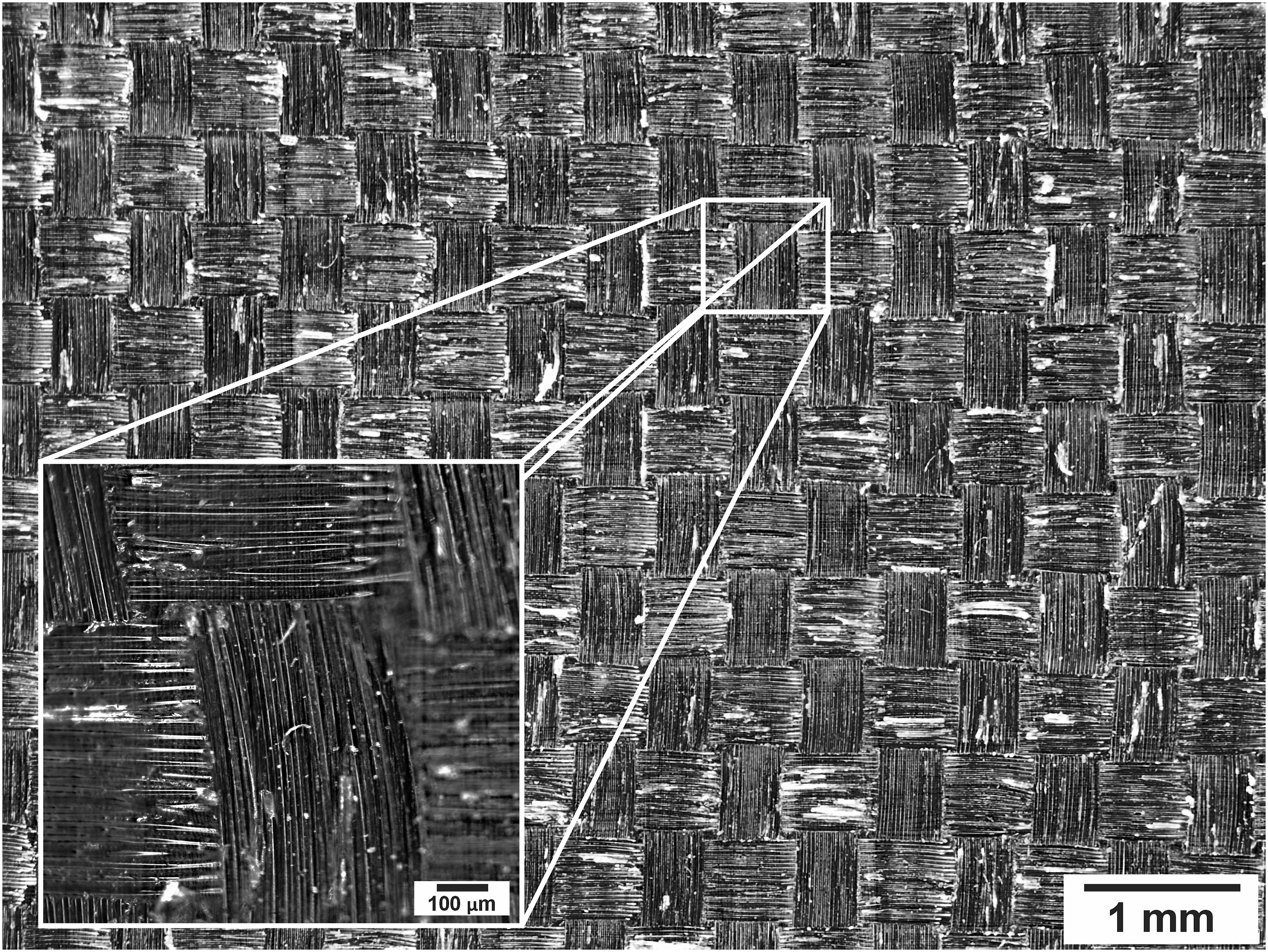
Composite laminate (CL) was manufactured by the vacuum-assisted resin infusion process (Figure 1). For the matrix, 0.32 g of hardener was mixed per gram of epoxy resin Epolam 2015 (viscosity of 550 mPa∙s at 25°C). 12 layers of bidirectional carbon fiber fabric (0/90°, 1000 filaments, Weight 125 g/m2, thickness 0.16 mm) shown in Figure 2, were arranged in a stacked manner on a base, then a non-stick fabric, a distribution mesh and a vacuum bag with polyurethane tape were placed to seal the system, ensuring there were no leaks. The epoxy resin was injected with a vacuum pressure of 750 mm to impregnate the carbon fibers. The curing process was carried out for 4.5 h at 60°C. At the end of the process, a solid laminate of 250 × 250 mm with an approximate thickness of 3 mm was obtained. Detailed schematic diagram of the composite laminate manufacturing process. Bidirectional carbon fiber fabric.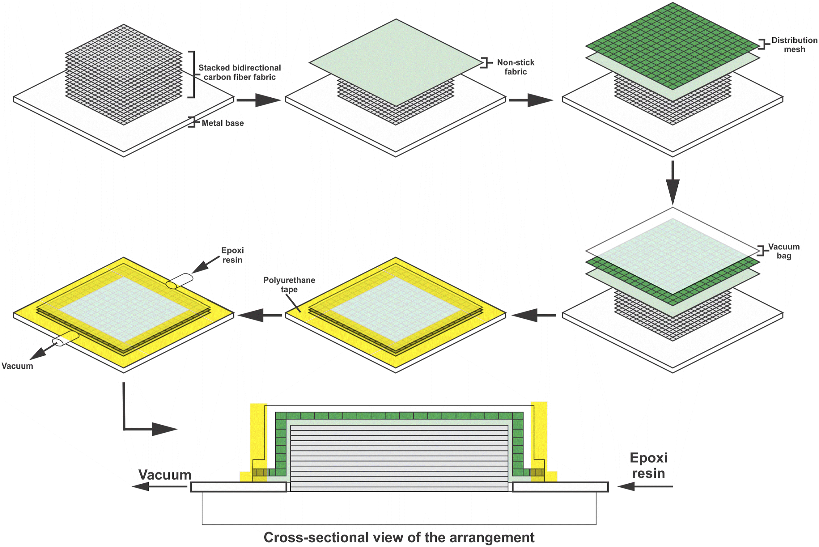
The specimens were cut to 20 × 50 mm, which were washed with soap and water in an ultrasonic bath for a period of 10 minutes at 40 kHz, and finally they were left to dry at room temperature. Figure 3 shows the carbon fiber layers present in the cross section of the epoxy resin matrix. Composite laminate cross section.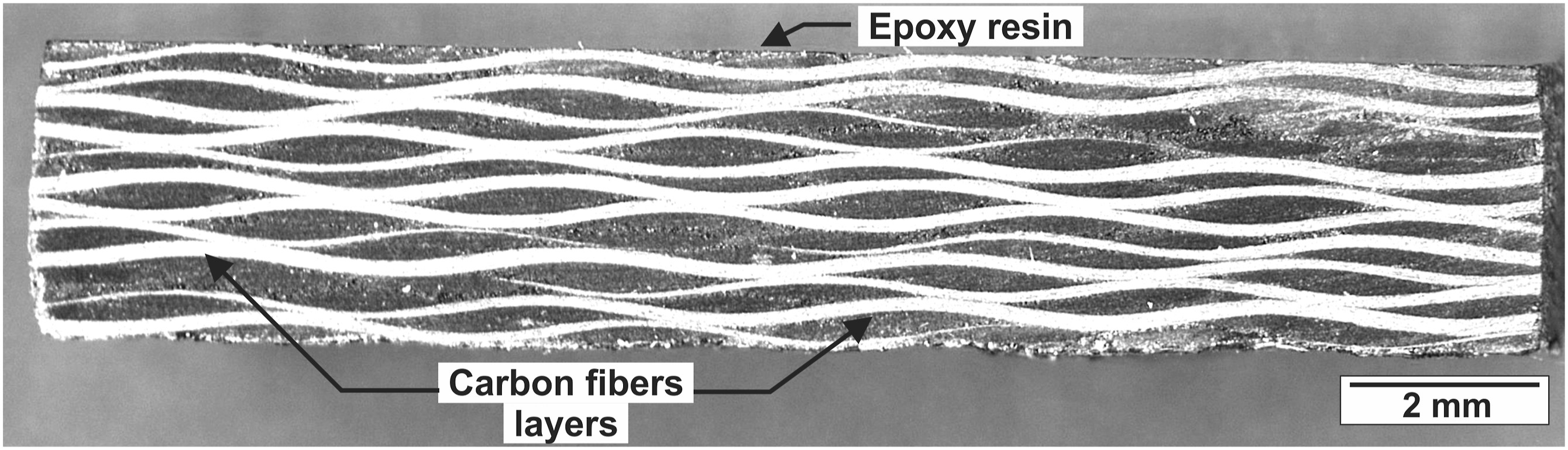
Transformation from graphite to GO
To obtain GO, a homemade high-energy mill (shaker) was used (Figure 4), inside the vial 1 g of high-purity 325 mesh (45 μm) graphite powder and 6 steel balls of 9.5 mm diameter (5.6 g weight ball) were placed for 90 minutes at 1200 RPM. The ball-to-powder ratio and the specific energy input of the milling were 34:1 and 2.25 kWh/g, respectively. This transformation process has already been reported.
38
Schematic diagram of the high energy mill, 1: electric motor, 2: flexible coupling, 3: transmission shaft, 4: bearings, 5: flywheel, 6: eccentric bearing, 7: vial holder and 8: vial.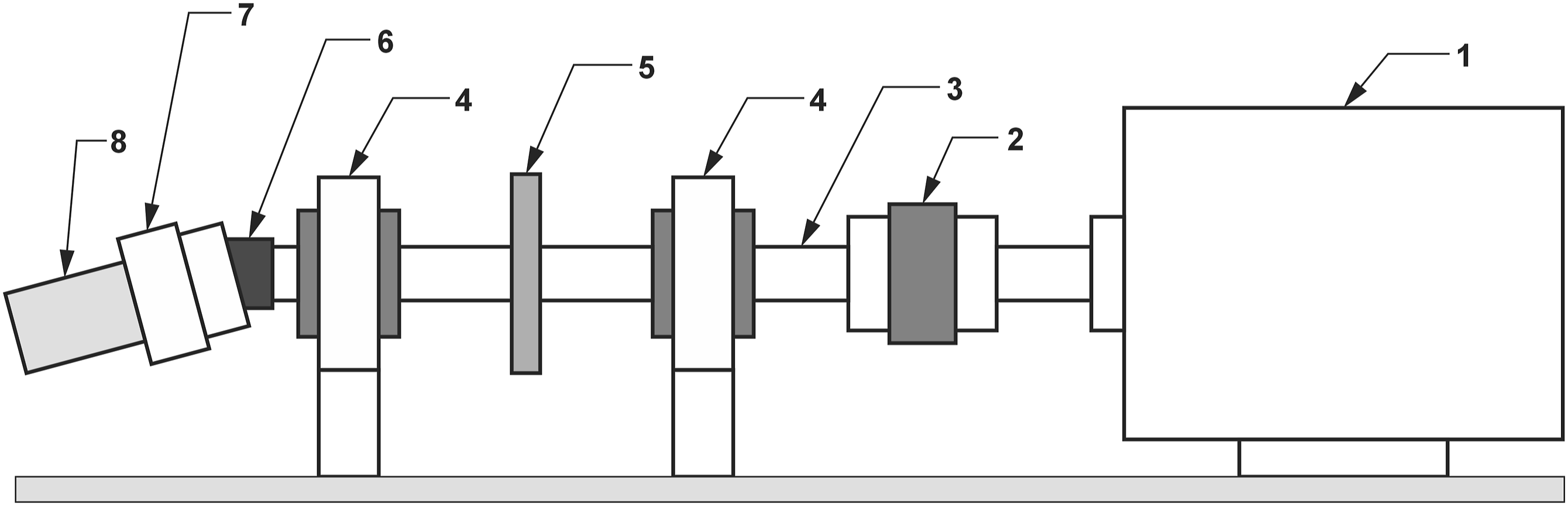
The XRD patterns of graphite and GO are shown in Figure 5, these data were obtained in a Rigaku smartlab diffractometer, using CuKα radiation (λ = 1.5406Å). The characteristic peaks of graphite are observed at the angles 2ϴ = 26.4 and 54.5°, which correspond to the reflections (0 0 2) and (0 0 4) of the structure of hexagonal graphite, respectively.39,40 GO presents characteristic broad diffraction peaks at 2ϴ = 26.1 and 43.7°, which are due to the disorder generated during GO obtaining.41,42 XRD patterns of graphite and GO.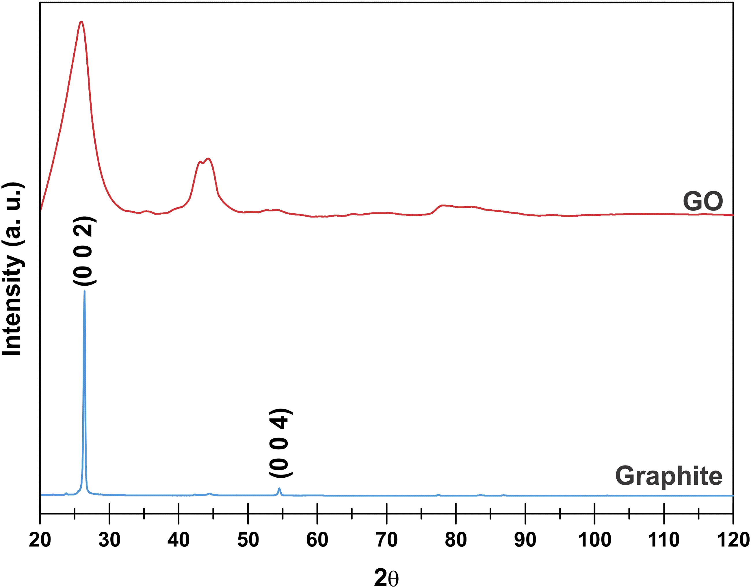
Erosive particle
Figure 6 shows the erosive particle used for the tests, in this case it was beach sand from the Tecolutla region, Veracruz, Mexico. The shape of this sand presents round, angular and subangular grains. Its chemical composition consists of silica globules, silica pellicle, sediments (volcanic rock, magnetite, pyroxenes, amphibole and limestone) and adhered NaCl particles.
43
Erosive particle.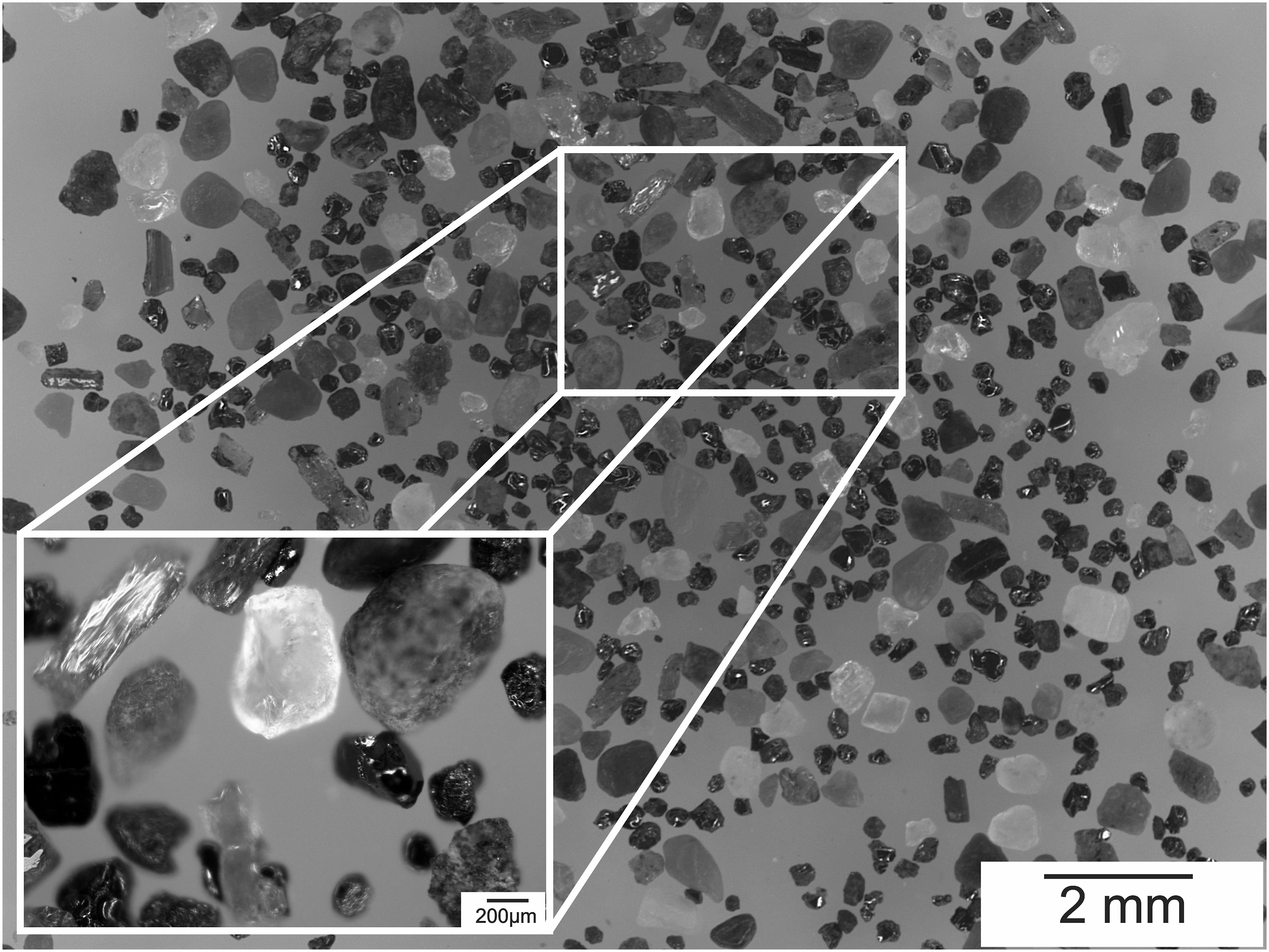
The static image analysis method was applied to obtain the particle size distribution shown in Figure 7.44,45 A stereoscope was used to capture an image, where the diameter of 100 particles from different regions was measured. The particle size with the greatest presence was 283.6 μm. Regarding percentage values of particle size, it was determined that d10 = 215.5, d50 = 297.38 and d90 = 384.11 μm. Particle diameter distribution.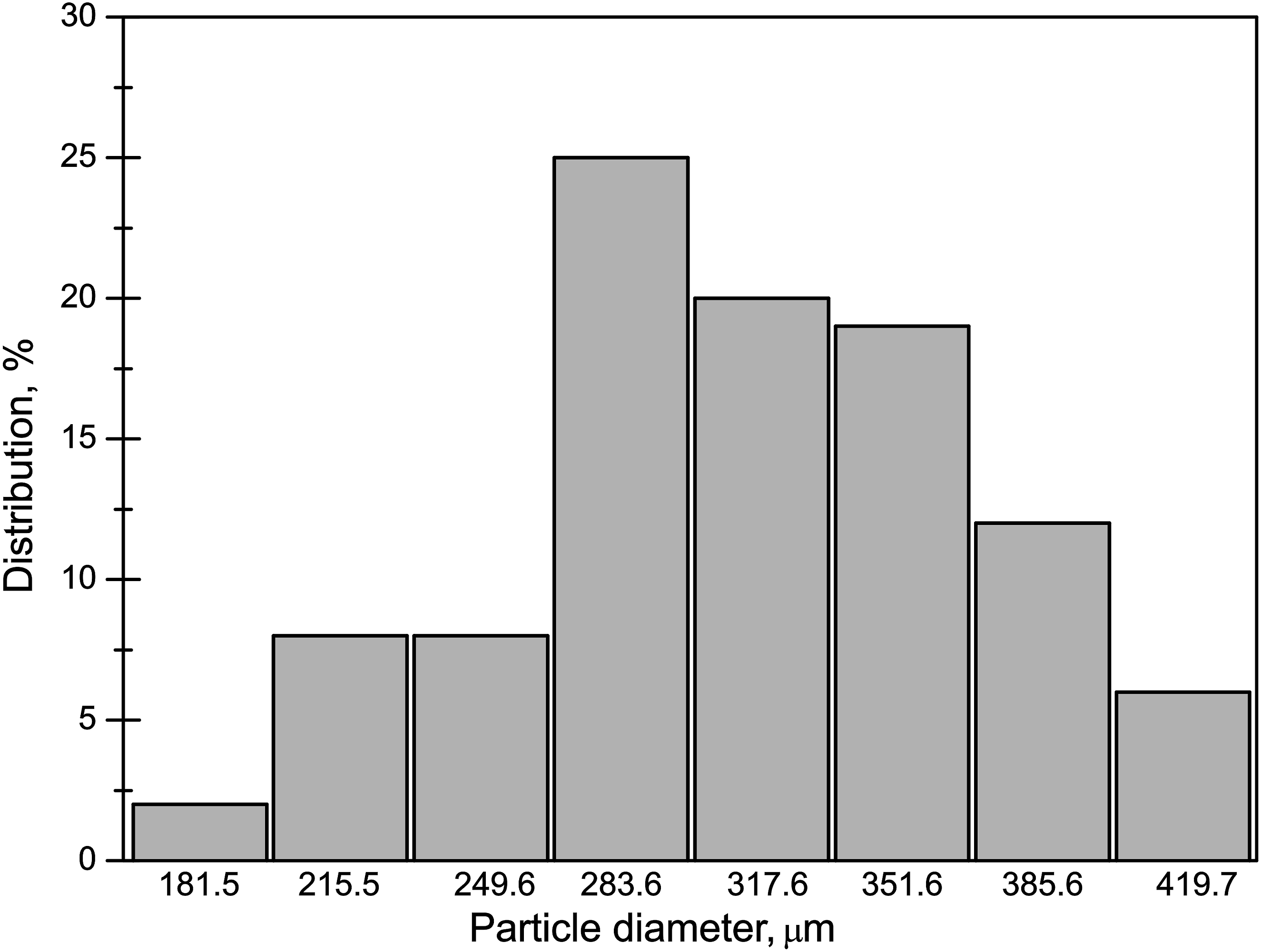
Preparation of PMMA/SiO2
The polymer solution was prepared by adding 1.67 g of polymethylmethacrylate (PMMA (Aldrich, Mw = 350,000 g/mol)) in 50 mL of acetone at 50°C and constant stirring for 30 minutes.
To obtain SiO2, using the sol-gel route at room temperature, 10 mL of Tetraethylorthosilicate (TEOS (Aldrich)) were added to 40 mL of ethanol (EtOH (Hycel)) while stirring for 20 minutes, then 33 mL of distilled water (H2O (Chemika reagents)) was added leaving it to stir for 5 minutes. It was finished by adding 1 mL of a solution of hydrochloric acid (HCl) (0.5 M) leaving it stirring for 10 minutes.
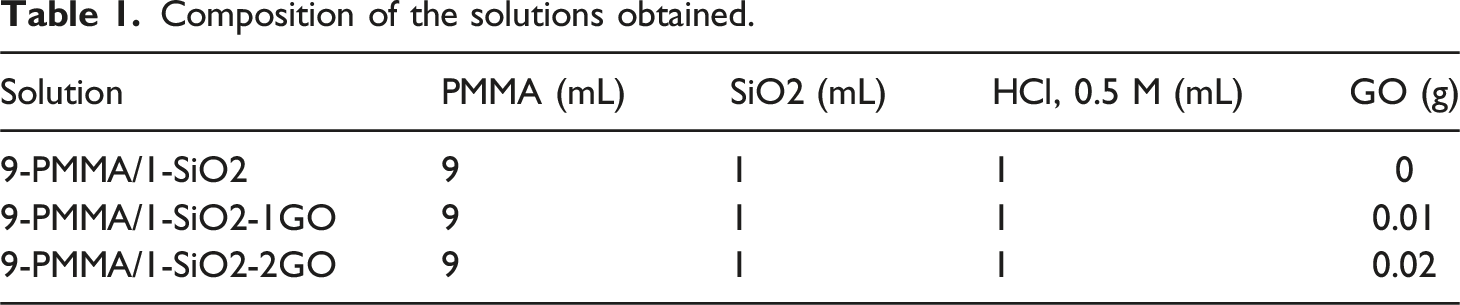
A reference PMMA/SiO2 hybrid solution was prepared with a volume ratio (mL/mL) of 9/1, which was assigned the name 9-PMMA/1-SiO2. The process was carried out by gradually adding SiO2 to the PMMA solution at room temperature, leaving it to continuously stir for 30 minutes, obtaining a transparent and homogeneous solution.
Preparation of PMMA/SiO2 with GO
Composition of the solutions obtained.
Coating deposition
All coatings were deposited on the CL substrates at room temperature using a dip-coater for 1 minute (Figure 8(a)). The speed at which the substrates were immersed and removed from the solution was 2.5 mm/s. To dry the coatings, they were placed inside a temperature chamber at 50°C for 10 minutes. In the case of the 9-PMMA/1-SiO2 solution coating, only the substrate was immersed in a conventional manner (Figure 8(b)). For the application of the coatings from 9-PMMA/1-SiO2-1G and 9-PMMA/1-SiO2-2G, the solutions were placed in an ultrasonic bath at 40 kHz for 1 minute of immersion of the substrate, in order to improve the dispersion of the GO,47–49 as shown in Figure 8(c). (a) Dip-coater front simplified schematic diagram, 1: linear guide rod, 2: Lead screw, 3: drying chamber, 4: sample holder, 5: substrate, 6: motor, (b) side view with solution container and (c) side view with ultrasonic bath.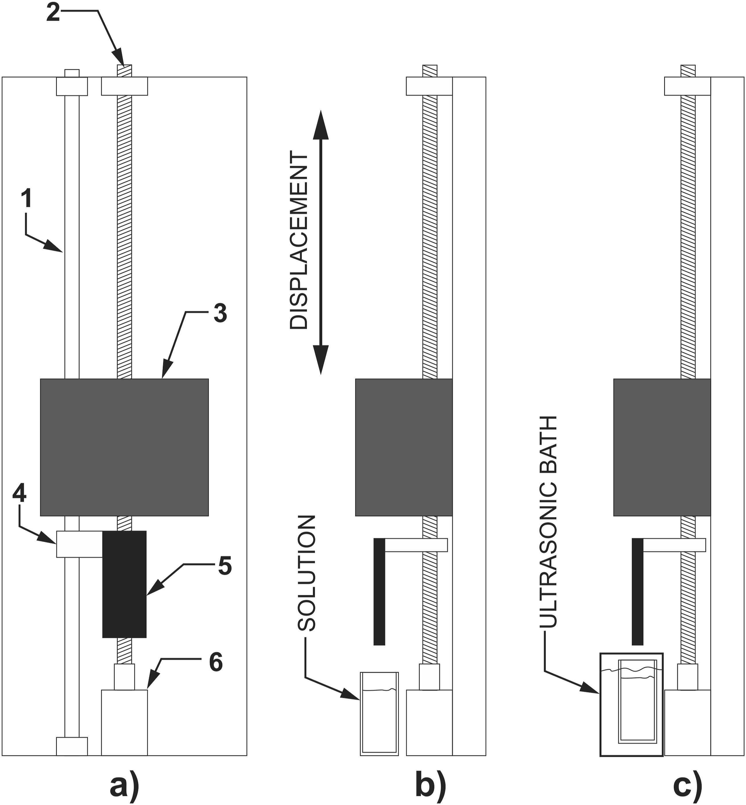
Characterization of substrate and coatings
The chemical composition was verified by Fourier transform infrared spectroscopy (FTIR) using attenuated total reflectance (ATR) on a Spectrum GX Perkin Elmer equipment. The average hardness was obtained in a Vickers durometer with an applied load of 1 g for 10 seconds, 10 measurements were made in different regions per coating. The wear track profile and roughness measurement of the substrates and coatings were determined using a Mitutoyo SJ-410 profilometer. An olympus DSX-500 confocal microscope was used to identify the wear zone and a Jeol 1200F scanning electron microscope was used to observe the surface, wear mechanisms and thickness.
Erosive wear test
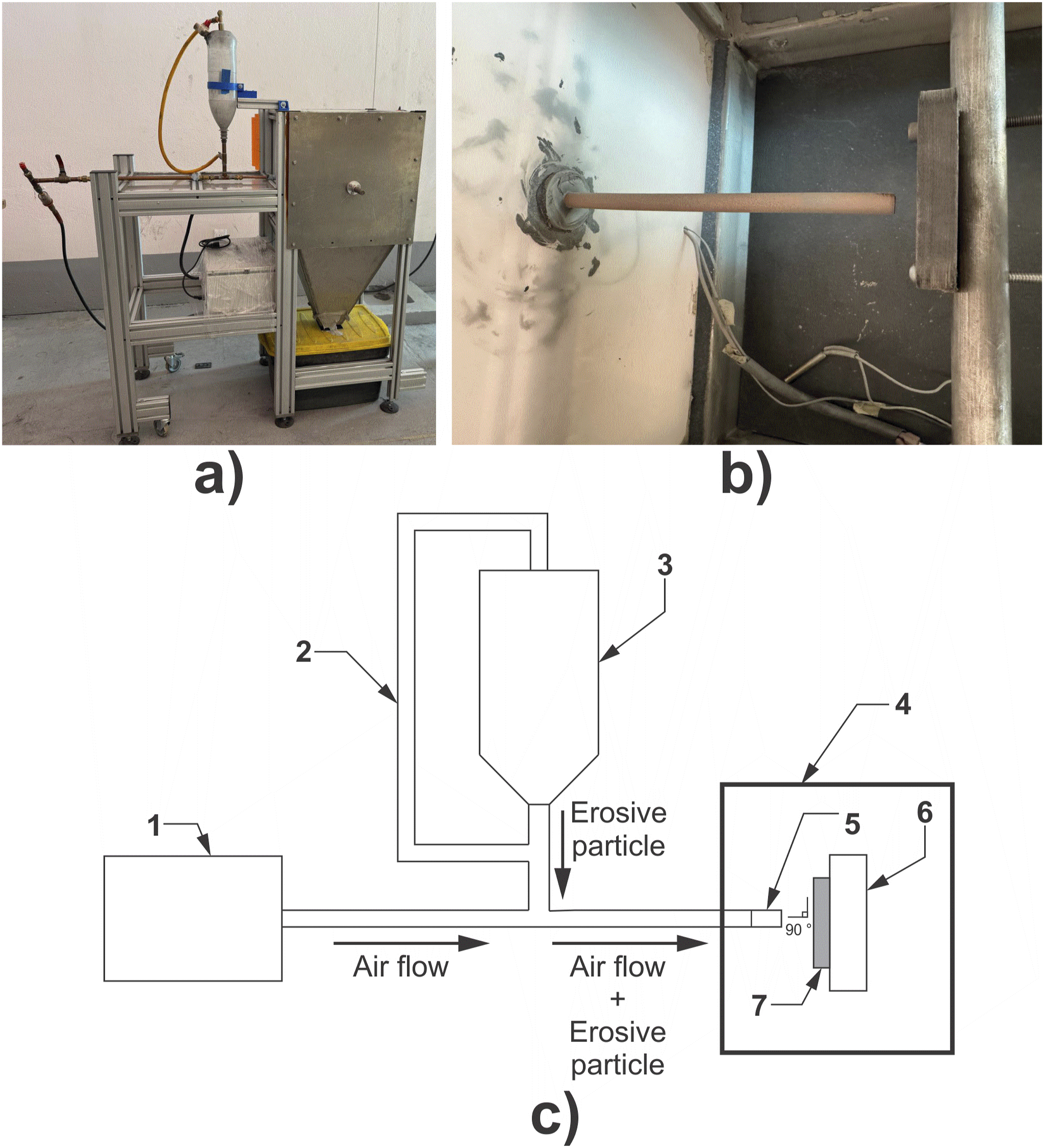
A homemade horizontal erosion test platform (Figure 9(a) and (b)), based on the ASTM standard G76
50
was used; a simplified schematic diagram is presented in Figure 9(c). The tests were carried out at room temperature using beach sand as the erosive particle. An air pressure of 45 psi and an impact speed of 6 m/s, measured with a PEAKMETER anemometer model PM6252B. The nozzle used has an inner diameter of 8 mm and a separation distance with the sample of 10 mm was considered with an impact angle of 90°, which was selected because it has been found to produce greater erosive damage per solid particle.18,19 Under the established conditions, a mass flow rate of 835 g/min of the erosive particle was used. Before the tests, the initial mass of each sample, using an analytical balance, was obtained. From the beginning of the tests, the sample was removed every 1 minute to record the amount of mass loss. This process was repeated until a total of 6 minutes. To select the duration of the erosion tests, some preliminary experimental tests were performed until observe an initial wear on the substrate (carbon fiber). Also, this selection was supported by previous work.18,19 Equation (1) was used to calculate the weight erosion rate ( (a) actual photograph of the horizontal erosion machine, (b) erosion chamber and (c) simplified schematic diagram of the horizontal erosion machine, 1: Air compressor; 2: feedback pipe; 3: erosive particle container; 4: erosion chamber; 5: nozzle; 6: sample holder; 7: sample.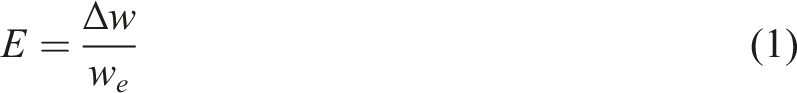
Results and discussion
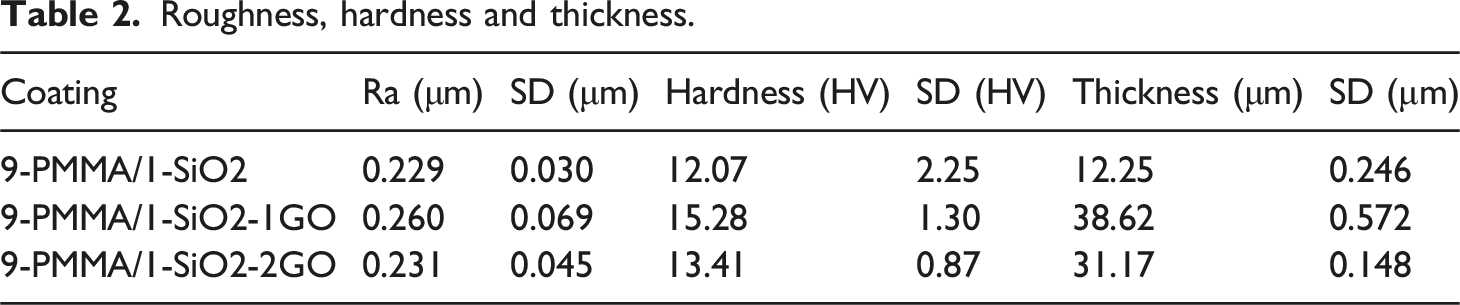
Roughness, hardness and thickness
Roughness, hardness and thickness.
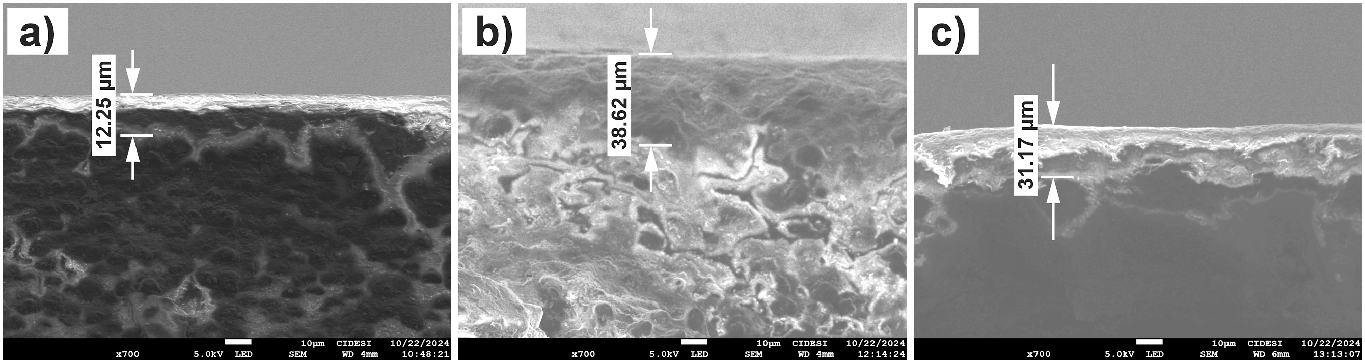
SEM images of the cross section of (a) 9-PMMA/1-SiO2, (b) 9-PMMA/1-SiO2-1GO and (c) 9-PMMA/1- SiO2-2GO.
FTIR, SEM and EDS
Figure 11(a) shows the infrared spectrum obtained from the 9-PMMA/1-SiO2, 9-PMMA/1-SiO2-1GO and 9-PMMA/1-SiO2-2GO coatings. Within the organic composition provided by PMMA, in the region from 3070 to 2760 cm−1, the bands corresponding to the C-H stretching of α-methyl, methyl ester and methylene were presented.
55
A band was observed at 1727 cm−1 that corresponds to the stretching vibration of the carbonyl ester group.
56
The broad band that occurred at 1147 cm−1 is due to the vibration of the ester bond (C-O).
57
The bands at 826 and 809 cm−1 correspond to the vibrations of the ester group.
58
In 9-PMMA/1-SiO2-1GO and 9-PMMA/1-SiO2-2GO with respect to their inorganic composition, at 750 cm−1 the band assigned to the symmetric stretching of the oxygen atoms of Si-O- was found.
59
The bands at 1147 and 1084 cm−1 are associated with the antisymmetric stretching vibration of the Si-O-Si bonds.
60
The GO presented bands corresponding to the C = C, C = O and C-O groups at 1605, 1727 and 1147 cm−1 respectively, resulting in more intense in 9-PMMA/1-SiO2-1GO. In Figure 11(b), the band corresponding to the OH of GO was observed at 3441 cm−1, again in 9-PMMA/1-SiO2-1G it is more intense, this confirms the presence and good dispersion of GO in the matrix of this coating.61–63 (a) FTIR Spectrum and (b) magnification.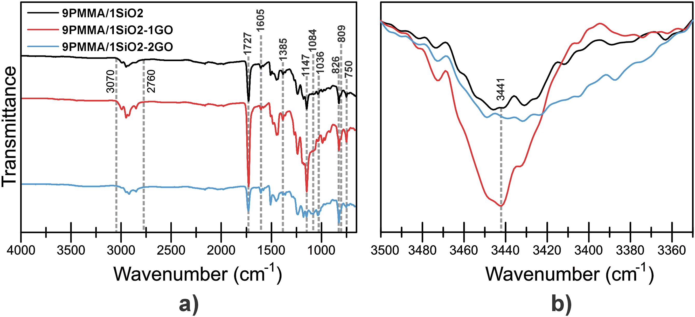
Figure 12 shows a SEM images of the surface of 9-PMMA/1-SiO2, 9-PMMA/1-SiO2-1GO and 9-PMMA/1-SiO2-2GO with magnifications of 500X and 1500X. In Figure 12(a), agglomerations of SiO2 are observed, which are located in the direction of the application of the 9-PMMA/1-SiO2 coating. In Figure 12(b), a uniform distribution of SiO2 is clearly observed. This is due to the application conditions of the coating and the concentration of GO in 9-PMMA/1-SiO2-1GO, which allowed a good interaction between GO, PMMA and SiO2.64,65 Regarding 9-PMMA/1-SiO2-2GO, a minimum distribution of SiO2 is observed in Figure 12(c). SEM images of (a) 9-PMMA/1-SiO2, (b) 9-PMMA/1-SiO2-1GO and (c) 9-PMMA/1-SiO2-2GO.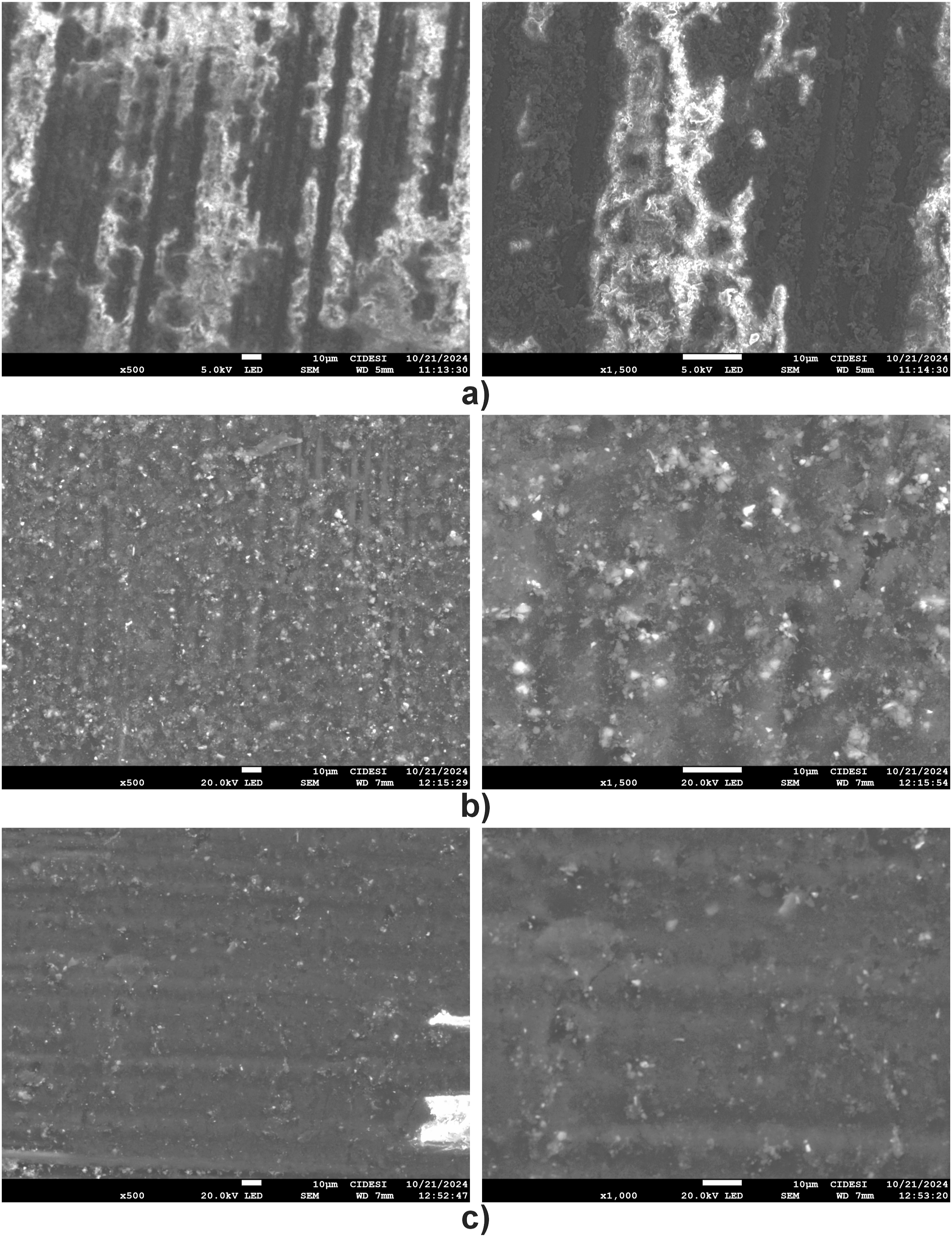
Figure 13 presents the EDS mappings of carbon, oxygen and silicon of 9-PMMA/1-SiO2-1GO and 9-PMMA/1-SiO2-2GO. Figure 13(a) shows a uniform distribution of carbon, silicon and oxygen. On the other hand, Figure 13(b) shows large agglomerations of oxygen and silicon. . EDS mapping of (a) 9-PMMA/1-SiO2-1GO and (b) 9-PMMA/1-SiO2-2GO.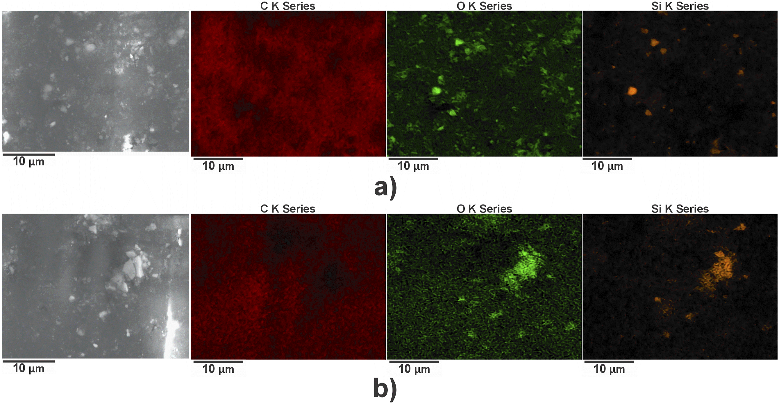
Mass loss, erosion rate and profilometry
Figure 14(a) shows the average mass loss results per minute of the coatings evaluated in the erosion tests. In 9-PMMA/1-SiO2, the highest mass loss occurred between minutes 0 and 2, corresponding to the detachment of the coating and the epoxy resin matrix; subsequently, the mass loss per minute was lower, this is because erosion reached the carbon fibers, which detach more slowly. In 9-PMMA/1-SiO2-1GO its greatest mass loss was within the interval from minute 0 to 3 and in 9-PMMA/1-SiO2-2GO between minute 0 and 4, this reduction in the rate of mass loss corresponds to the protection provided by the coatings containing GO; afterwards, in both cases, it is observed that the mass loss is lower because the fibers were reached. The error bars observed in each value of mass loss in Figure 14(a) correspond to small variations in the air supply to the system, due to the loading and unloading of the compressor, however, the results maintain the trend with respect to the mass loss of the materials evaluated. Figure 14(a) presents the image contrast of the deepest region and in the box the total area affected by erosion, in which it is observed that 9-PMMA/1-SiO2-1GO exhibits the least amount of deep regions and total zone affected, while 9-PMMA/1-SiO2 and 9-PMMA/1-SiO2-2GO show large zones of depth and total zone affected. (a) Mass loss per minute and (b) image contrast of wear zone.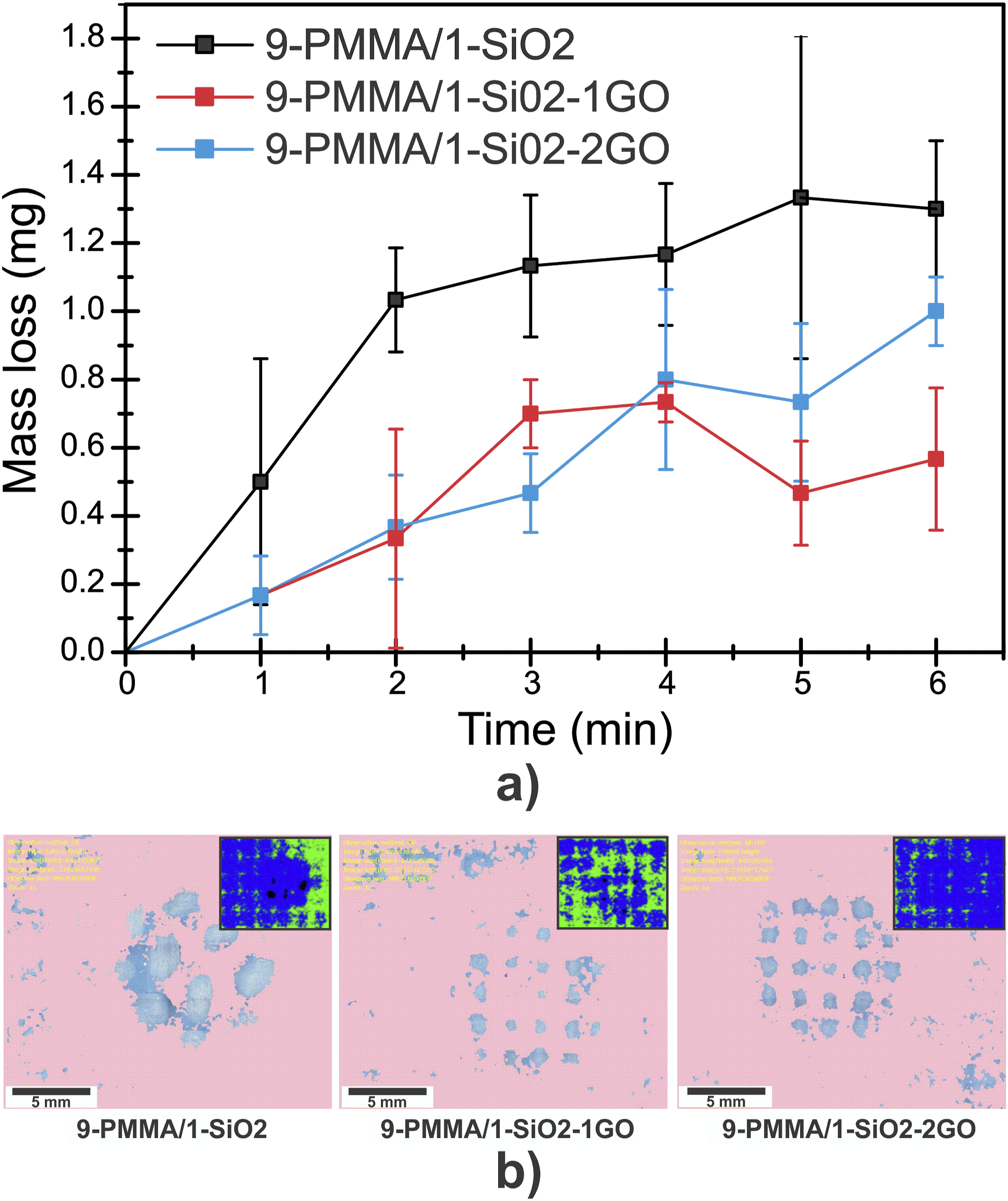
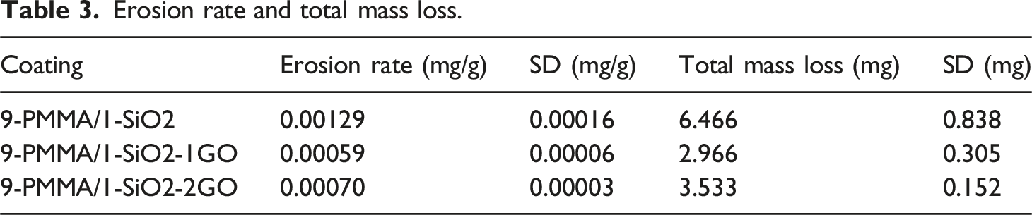
Figure 15 shows the results of the erosion rate, accumulated and the total mass loss per minute. It is observed in Figure 15(a) that 9-PMMA/1-SiO2 was the sample that accumulated the greatest mass loss of material at the end of the test, due to the rapid detachment of the coating, matrix and fibers, on the other hand, in 9-PMMA/1 -SiO2-1GO and 9-PMMA/1-SiO2-2GO the lowest accumulated loss was observed, demonstrating the increase in the protection of the coatings due to the presence of GO. The erosion rate and total mass loss shown in Figure 15(b) indicates that 9-PMMA/1-SiO2 presented the greatest wear and 9-PMMA/1-SiO2-1GO the least wear. Based on this, it is confirmed that the incorporation of GO increases the protection against erosive wear of the material by approximately between 50 (9-PMMA/1-SiO2-2GO) to 54% (9-PMMA/1-SiO2-1GO). Table 3 presents the results of the erosion rate and total mass loss of the evaluated coatings. (a) Cumulative, (b) erosion rate and total mass loss. Erosion rate and total mass loss.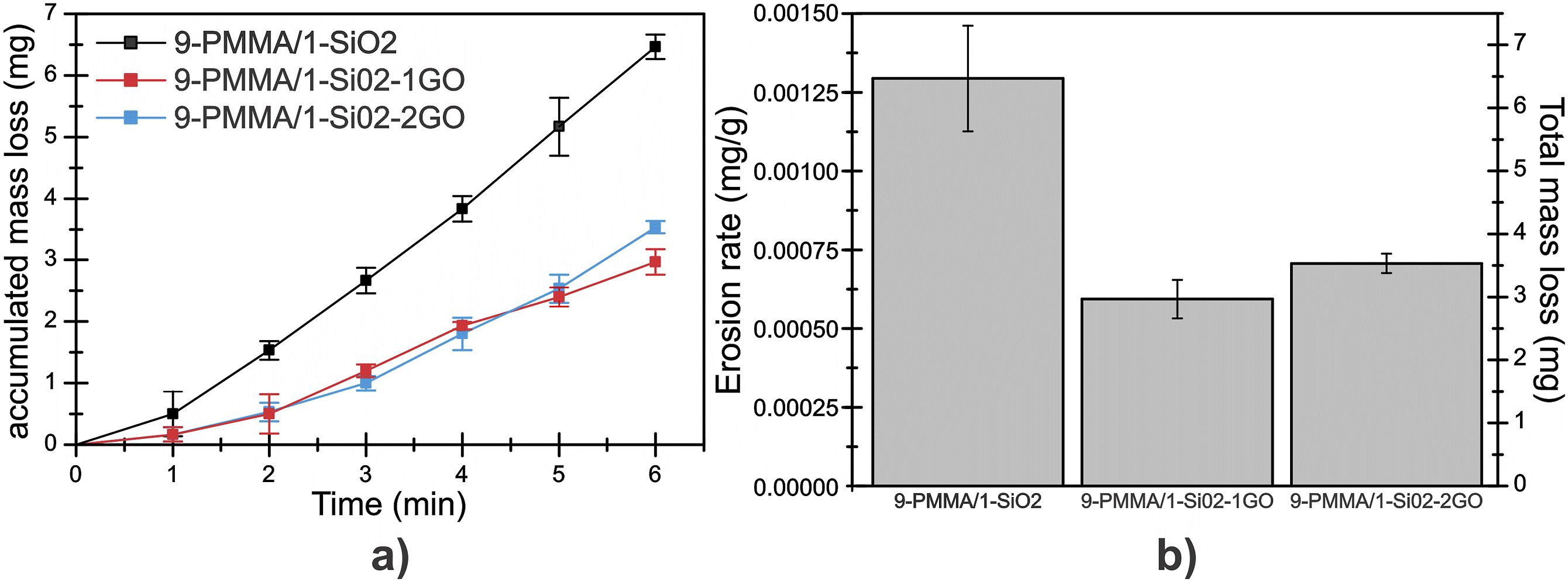
The profilometry performed in the erosive wear zone of the 9-PMMA/1-SiO2, 9-PMMA/1-SiO2-1GO and 9-PMMA/1-SiO2-2GO is presented in Figure 16(a). It was observed that the specimen with the greatest depth after the test was 9-PMMA/1-SiO2, while 9-PMMA/1-SiO2-1GO presented the lowest depth. Figure 16(b)–(d) show the erosion wear zone of all the specimens, it is observed that the 9-PMMA/1-SiO2-1GO presented the least eroded wear zone, despite this, in all cases there were exposed fibers. These results confirm what was previously shown in the erosion rate, mass loss per minute and total. (a) Perfilometry and erosion wear of (b) 9-PMMA/1-SiO2, (c) 9-PMMA/1-SiO2-1GO and (d) 9- PMMA/1-SiO2-2GO.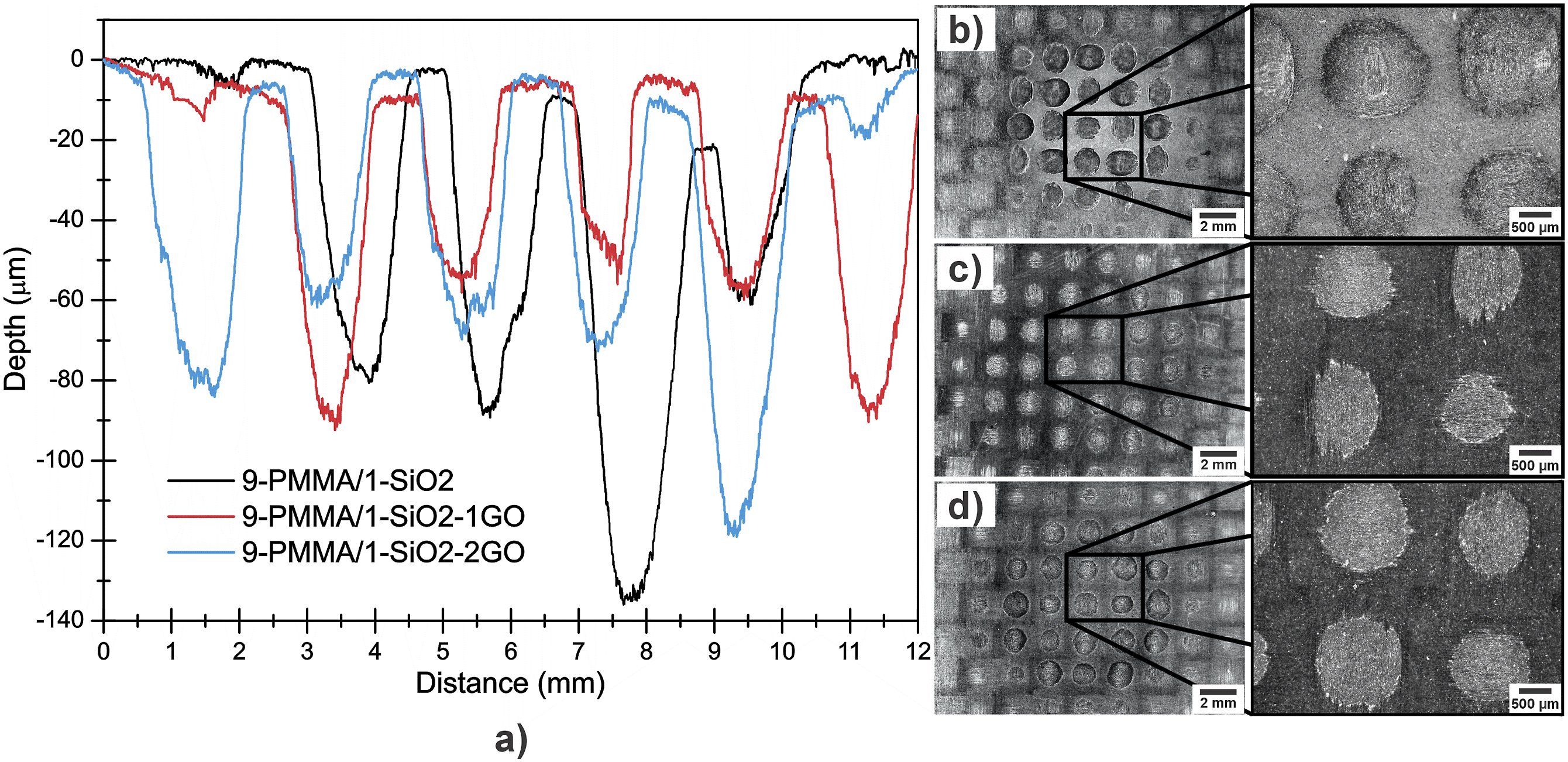
Wear mechanisms
Figure 17 shows the images obtained at a magnification of 500X and 1500X by SEM of the wear trace of 9-PMMA/1-SiO2, 9-PMMA/1-SiO2-1GO and 9-PMMA/1-SiO2-2GO coatings. From the erosion test due to the normal impact (90°) of the particles on the surface, it was ensured that maximum damage was generated,
66
starting with the detachment of the coatings and the epoxy resin matrix until causing fiber exposure, which became thinner and detached from the matrix, leaving some gaps allowing the subsequent fibers to be observed. In Figure 17(a)–(c), it is observed in the wear zone that the epoxy resin matrix presented brittle failure, which is considered a characteristic wear mechanism of a thermostable polymer.67,68 With respect to carbon fibers, breaks, cutting action and fragmentation occurred in 9-PMMA/1-SiO2, 9-PMMA/1-SiO2-1GO and 9-PMMA/1-SiO2-2GO. From the results of hardness, thickness, mass loss, profilometry and erosion rate, in addition to a lower amount of exposed fibers (Figure 17(b)), it is confirmed that 9-PMMA/1-SiO2-1GO was the material evaluated that presented less damage. This was due to the presence of GO, which improved the properties of the PMMA/SiO2 matrix,69,70 therefore there was a reduction in its erosive wear.
71
In 9-PMMA/1-SiO2 and 9-PMMA/1-SiO2-2GO, due to the absence and poor distribution of GO, respectively, a greater amount of exposed fibers and erosive wear occurred (Figure 17(a) and (c)). Under the test conditions, the erosion mechanism of removal of the coating and matrix predominated, as well as the exposure of the carbon fibers for subsequent fragmentation and detachment. Wear mechanism at 500 and 1500X of (a) 9-PMMA/11SiO2, (b) 9-PMMA/11SiO2-1GO and (c) 9- PMMA/11SiO2-2GO.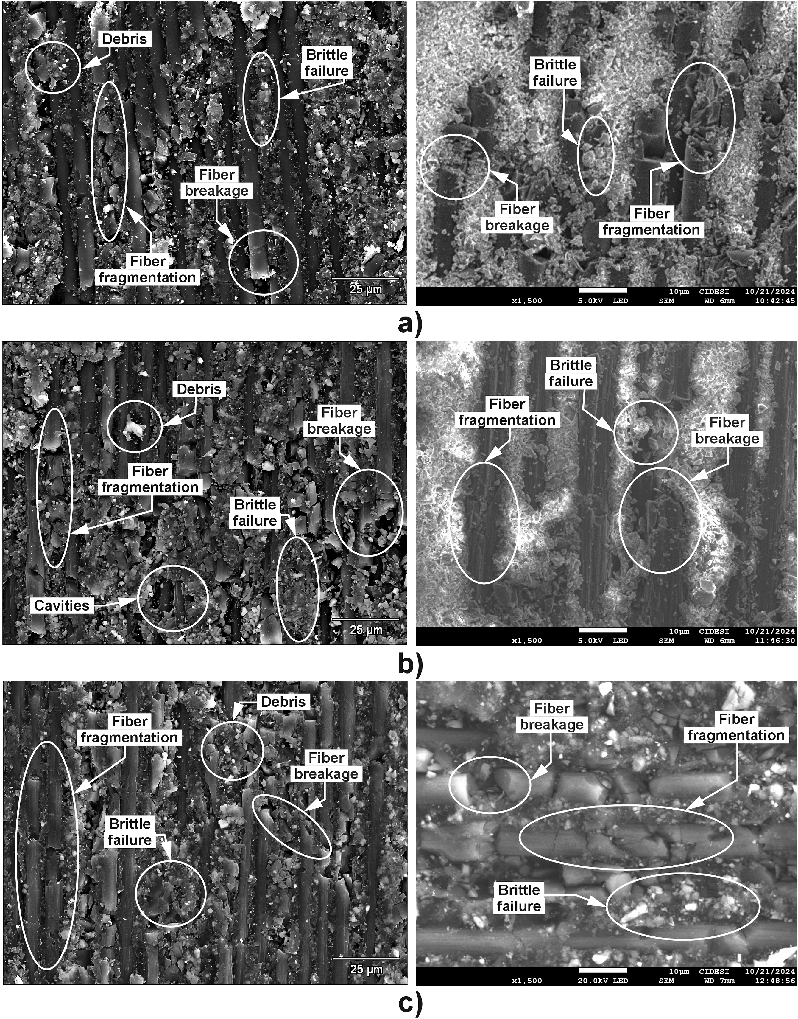
Conclusions
In this research work, the erosive wear performance of a series of PMMA/SiO2 coatings reinforced with 0, 0.01 and 0.02 g of GO was determined.
Using a high-energy mill, the transformation of graphite to GO was carried out and confirmed with XRD analysis performed, which was correctly incorporated into a 9-PMMA/1-SiO2 hybrid solution to obtain 9-PMMA/1-SiO2-1GO and 9-PMMA/1-SiO2-2GO.
The use of an ultrasound bath at 40 kHz for 1 minute was effective to improve the dispersion of GO (0.01 g) when depositing the 9-PMMA/1-SiO2-1GO on the substrates by dip coating. This was verified from the results obtained from FTIR, SEM and EDS.
The 9-PMMA/1-SiO2-1GO coating stood out for providing an additional protection of approximately 54% compared to 9-PMMA/1-SiO2, this was validated from the results of hardness, erosion rate, loss of mass and wear mechanisms.
Therefore, particularly at the conditions tested, the 9-PMMA/1-SiO2-1GO coating can be considered as a protective alternative that is easy to apply on the leading edge of wind turbines blades, in order to reduce the wear and extend their useful life time.
Footnotes
Acknowledgements
We thank the National Council of Science and Technology (CONAHCyT) for the scholarship granted to carry out postgraduate studies. To the Center for Engineering and Industrial Development (CIDESI) Querétaro Unit, for support in the characterization of the materials.
Declaration of conflicting interests
The author(s) declared no potential conflicts of interest with respect to the research, authorship, and/or publication of this article.
Funding
The author(s) received no financial support for the research, authorship, and/or publication of this article.