
Abstract
In this work microwave micro arcing (MwMA) has been utilized to engineer the surfaces of carbon fibers (CF) to enhance the interfacial bonding of resulting PEEK based composites. The CF were subjected to MwMA at different power levels ranging from 360 W to 900 W for 60 s to engineer their surfaces. The influence of MwMA on CF at various power levels was analyzed using SEM, contact angle measurement, AFM scans, and XPS study. Subsequently, MwMAed CF reinforced PEEK composite laminates were developed using compression molding. The MwMA on CF increased the surface wetting energy by 38% at 540 W microwave power level. XPS analysis suggested that MwMA at 540 W introduced oxygen containing functional group (C-O and C = O), which are likely responsible for increasing the adhesion between CF and PEEK polymer. The current study suggests that MwMA CF at 540 W showed an increment in tensile strength, flexural strength, interlaminar shear strength, and impact strength nearly by 22%, 61%, 28%, and 98% respectively. The MwMA method is novel method to improve the surface properties of carbon fibers and shows the potential use in structural applications.
Keywords
Introduction
Recently, there has been significant research interest in developing sustainable structural composites using advanced thermoplastics. Thermoplastic polymer-based composites offer recyclability, reusability, and lower environmental carbon footprint. 1 Most of the thermoplastic polymers soften at higher temperatures and degrade under ultraviolet (UV) irradiation. They are also more expensive and possess low strength compared to thermoset polymers.2,3 Advanced thermoplastic such as poly-ether-ether-ketone (PEEK), poly-phenylene-sulfide (PPS), poly-aryl-ether-ketone (PAEK), etc., exhibits high toughness, impact strength, resistance to chemical attack, less degradation by UV radiations and high service temperature.4–6 But high viscosity, poor adhesion to fibers, solid state at room temperature, and high processing temperatures limit the use of these advanced thermoplastics in advanced structural applications. 6
Poly-ether-ether-ketone (PEEK) is an advanced thermoplastic material with good mechanical, thermal, and chemical properties. 4 PEEK thermoplastic has a wide area of applications such as aerospace, automotive, biomedical, oil and gas sector, electrical, etc. 6 The properties of PEEK can further be enhanced by adding fibers and fillers.3,5,7 The most common fibers used in structural application is carbon fibers (CF) which have superior mechanical properties compared to other synthetic fibers. 8 CF offer high specific strength, high modulus, and high-temperature resistance. 9 Although CF provides superior properties and makes them suitable for structural applications, their smooth surface and low surface energy make it difficult to form strong interfacial bonding with PEEK thermoplastic. 10 The mechanical properties of composites depend not only on the properties of matrix and fiber but are highly influenced by interfacial bonding between them. 8 Proper interlocking between fiber and matrix enhances the strength of resulting composites.8,11 Carbon fibers are generally coated with a polymer layer known as sizing. Sizing acts as a protective layer around the carbon fibers, protecting them from abrasion, damage, and environmental conditions. However, this sizing layer reduces adhesion between carbon fibers and the PEEK matrix. 7 Various methods like chemical treatment, ultrasonic cleaning, and plasma treatment modify this sizing.12–14 Furthermore, introducing polar functional groups like hydroxyl, amino, carboxyl, and epoxide groups, and addition of fillers material also helps improve the bond between matrix and fibers. 15 Chen and Li developed a method of depositing the silicon dioxide (SiO2) layer over the surface of carbon and graphite fibers to improve the adhesion between carbon and magnesium (C/Mg) composites. The layer of SiO2 over the fiber surface improves the wetting and interfacial bond strength between fiber and matrix, subsequently improving the mechanical strength. 14 Pathak et al. incorporated graphene oxide (GO) in the carbon fiber-based epoxy composites. Adding 0.3 wt% of GO increased the storage modulus of developed composites by 100%. 16 Ferreira et al. used wood powder in polypropylene to develop particulate composites. The developed composites showed improved interfacial adhesion due to the use of wood powder. 17 Guo et al. reported an increment in interlaminar shear strength (ILSS) and flexural strength of developed composites by 38.9% and 83.5%, respectively, using novel cation-π coating over CF surface. 18 Yao et al. improved the interfacial shear strength (IFSS) and model fracture toughness (GIC) of carbon fiber reinforced epoxy composites by depositing CNTs over the fiber surface and functionalizing CF by amino group. 19 Chirila et al. used oxygen plasma treatment on the carbon nano-fiber polymeric composites. Composites treated with 5 wt% oxygen plasma exhibited an 11% increase in tensile strength compared to composites manufactured with untreated fibers. This report also suggested that oxygen plasma treatment improved the wettability and surface energy of fibers. 20 Ahamad and Kumar reported improved mechanical strength of PEEK and polyetherimide (PEI) thermoplastic by surface modification using modified halloysite nanotubes (mHNTs). The developed PEEK/PEI blend-based composites also showed an increment of storage modulus by 25%. 3 Song et al. used an aqueous ammonia solution to improve the interfacial properties of carbon fibers reinforced epoxy-based composites. Carbon fibers were dipped in aqueous ammonia solutions for different lengths of time. The treating time of 48 h resulted in maximum tensile and interfacial shear strength values reducing thereafter. 21 All these chemical and surface modification techniques are effective but are also costly and time-consuming.
In recent times, microwaves have been used to modify the surface of fibers and rapidly curing polymers for faster development of fiber-reinforced composites.19,21 Wang et al. irradiated microwaves over the carbon fibers at 300 W. Microwave treatment showed improvement in interfacial adhesion between fiber and matrix. This was confirmed by an increment in interfacial shear strength (IFSS) by 98% compared with composites developed with untreated carbon fibers. 8 Nabais et al. used thermal treatment of activated carbon fibers (ACF) using microwave heating. The microwave-treated ACF showed a reduction in micropore volume and micropore size. Studies also showed that the short-period heating of ACF removed the acidic surface groups without removing oxygen and nitrogen; hence, it provided a basic nature to ACF. 22 Singh and Zafar incorporated the microwave energy to cure the polypropylene (PP) and polyethylene (PE) based composites, the curing time of developed composites using microwave was about 6% of time required in curing of composites using conventional autoclave method. Mechanical properties of microwave cured composites was found better or comparable to thermally cured composites. 23 Fu et al. investigated the effect of plasma treatment over the surface of carbon fiber in the presence of an oxygen environment. The developed CF reinforced ultra-high molecular weight polyethylene (CF/UHMWPE) showed a contact angle reduced from 75.69° to 36.56° after plasma treatment due to the formation of polar groups. The interlaminar shear strength (ILSS) of developed composites also increased by 18% after plasma treatment. 10 Zhao et al. compared the effect of microwave and conventional heat treatment of polyacrylonitrile-based carbon fibers. The fibers were treated in the temperature range of 180°C to 280°C. The microwave heat treatment of fibers showed a reduction in pre-oxidation time and reduced the number of defects over the surface of the fibers. 11 Significant research has been done to improve interfacial bonding between fibers and matrix using chemical methods and by using some additives.13,14,19 These chemical methods are effective, and uniform surface modification is possible. Microwave energy is utilized for the rapid curing of composites and a post-process treatment to increase the crystallinity and reduce the porosity of developed composites.7,19 The impact of microwave treatment over CF and resulting thermosets-based composites have been explored widely.8,24,25 Poor interfacial bonds between CF and PEEK cause low strength and limit the use of resulting composites.4,25 Surface modification of different fibers by microwave heating was researched in previous work.11,22 To the best of the author’s knowledge, very little is reported to improve interfacial bonding in CF-reinforced PEEK composites using the microwave micro arcing (MwMA) technique.
Therefore, in this work, the microwave micro arcing (MwMA) technique at different power levels is used to engineer the surface of CF for improved interfacial bonding in PEEK-based resulting composites. SEM, contact angles, AFM scans and XPS study assessed the surface morphology of engineered CF. Furthermore, the effect of MwMA is studied on the tensile strength, flexural strength, interlaminar strength (ILSS), and impact strength of engineered CF reinforced PEEK composites.
Experimental
Materials
Padmini Innovative Marketing Solutions Pvt. Ltd, Mumbai, India, supplied Victrex 450 G PEEK polymer. Unidirectional carbon fiber (UdCF) of 200 gsm sourced from BhorForce was used as reinforcement.
Microwave micro arcing (MwMA)
Carbon fibers were washed using acetone to remove dirt and reduce the polymer sizing thickness.
14
Consequently, fibers were dried in a hot air oven at 60°C for 24 h. Then, dried carbon fibers were placed in a multimode microwave applicator (Make: LG, Model: MC2886BLT) for microwave micro arcing (MwMA). The UdCF were irradiated in the microwave at the power levels of 360 W, 540 W, 720 W, and 900 W for 60 s. Carbon fibers absorb minimal microwaves due to the low dielectric factor (tan δ = 0.007 to 0.062).
9
The dielectric loss factor (tan δ) of material decides how much electromagnetic energy will be absorbed by materials and converted into heat, which is calculated using equation (1)
25
:
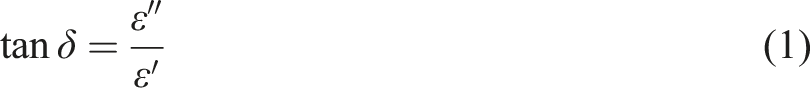
Due to the low dielectric loss factor, the reflection of microwaves is very high, and carbon fibers absorb very little microwaves. Hence, penetration through carbon fibers is very low, and heating generally occurs at the outer surface of carbon fibers.
26
The micron-level polymer sizing over the carbon fibers is generally introduced to protect its surface from external damage and environmental conditions.
7
The carbon fibers and sizing material have different dielectric loss factors. Generally, polymer sizing has a more dielectric constant (tan δ = 0.02 for epoxy-based sizing) than CF.
26
When oscillating, microwaves interact with carbon fibers and sizing material. Some parts of microwave energy are reflected and absorbed according to their dielectric loss factor. The polymer sizing absorbs more microwave energy than CF and accumulates more charges at the interface, as illustrated in Figure 1(a). This charge accumulation at the interface Figure 1(b) causes the formation of internal electric fields, as illustrated in Figure 1(c). The intensity of the electric field increases as more charge accumulates at the region of the CF and PEEK interface. This causes increase in the kinetic energy of free-moving electron and enables to jump out from carbon surface quickly, resulting in the ionization of nearby gaseous molecules, which is seen as arc plasma or discharges.
27
The micro arcing phenomenon in carbon fibers during microwave micro arcing (MwMA).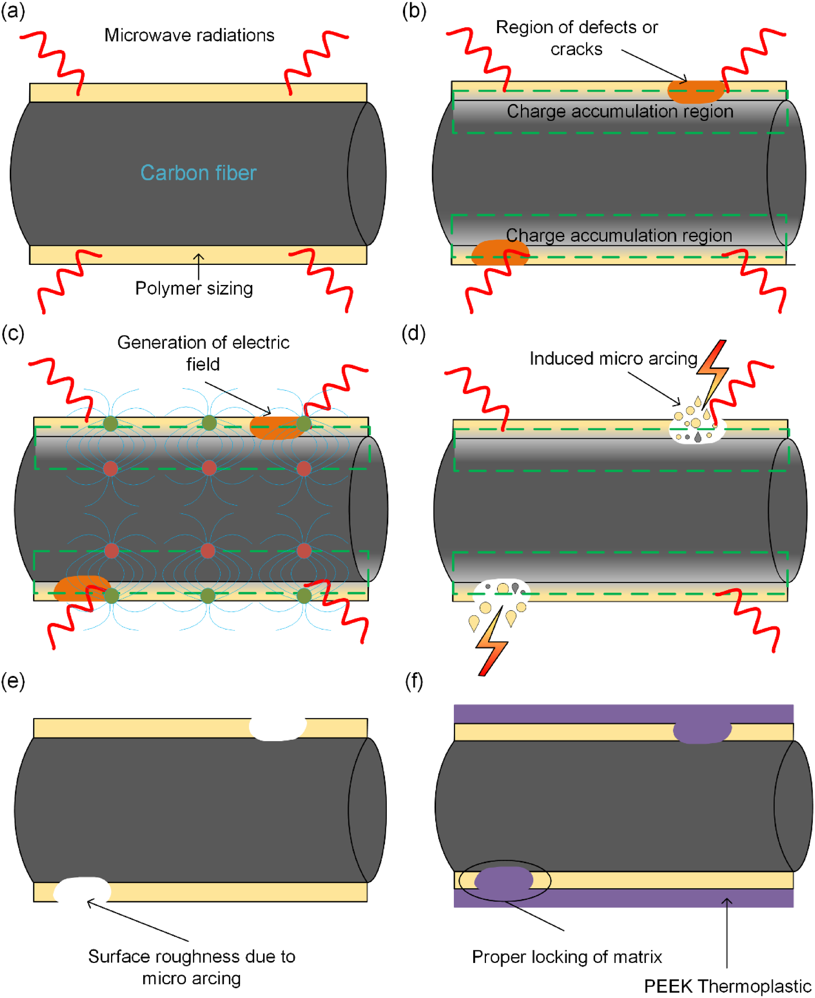
The electric flux (
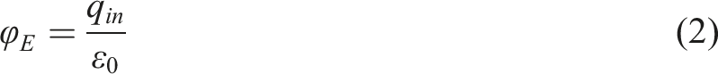
Even the smooth-appearing CF contains impurities, defects, and cracks over the surface, as illustrated in Figure 1(b). These impurities are potential sites of arcing as they are the region of heterogeneous distribution of conductive and non-conductive materials. The electric fields may become concentrated at these impurities. If the electric field’s strength exceeds the sizing material’s breakdown strength, it can lead to arcing, as seen in Figure 1(d). The arcing cause’s localized heating at the interface which removes some parts of the sizing layer, and produces some roughness on the carbon fiber surface, as illustrated in Figure 1(e). Due to the induced micro roughness over the CF surface, proper locking of the PEEK matrix is possible, as seen in Figure 1(f). Hence, mechanical properties can be improved due to better interfacial bonding. The observed micro-roughness and cracks can be understood by the Maxwell-Wagner polarization effect. This phenomenon arises due to the heterogeneous distribution of conductive and non-conductive materials, leading to the accumulation of electric charges at the interface of polymer sizing and carbon fibers.22,28 With the help of microwave treatment, the oscillation of electromagnetic fields induces localized heating at the interface of sizing and fiber, resulting in micro-roughness over the surface of carbon fiber, as shown in Figure 1(e). The carbon fibers were MwMA treated for 60 s at different power levels of 360 W, 540 W, 720 W, and 900 W. The MwMA is rapid and economical than the conventional heating. The conventional heating of carbon fiber consumes around 129000 kJ of energy for any significant change in surface propertites. 27 The MwMA treatment consumes around only 32.4 kJ at 540 W.
Preparation of composite laminates
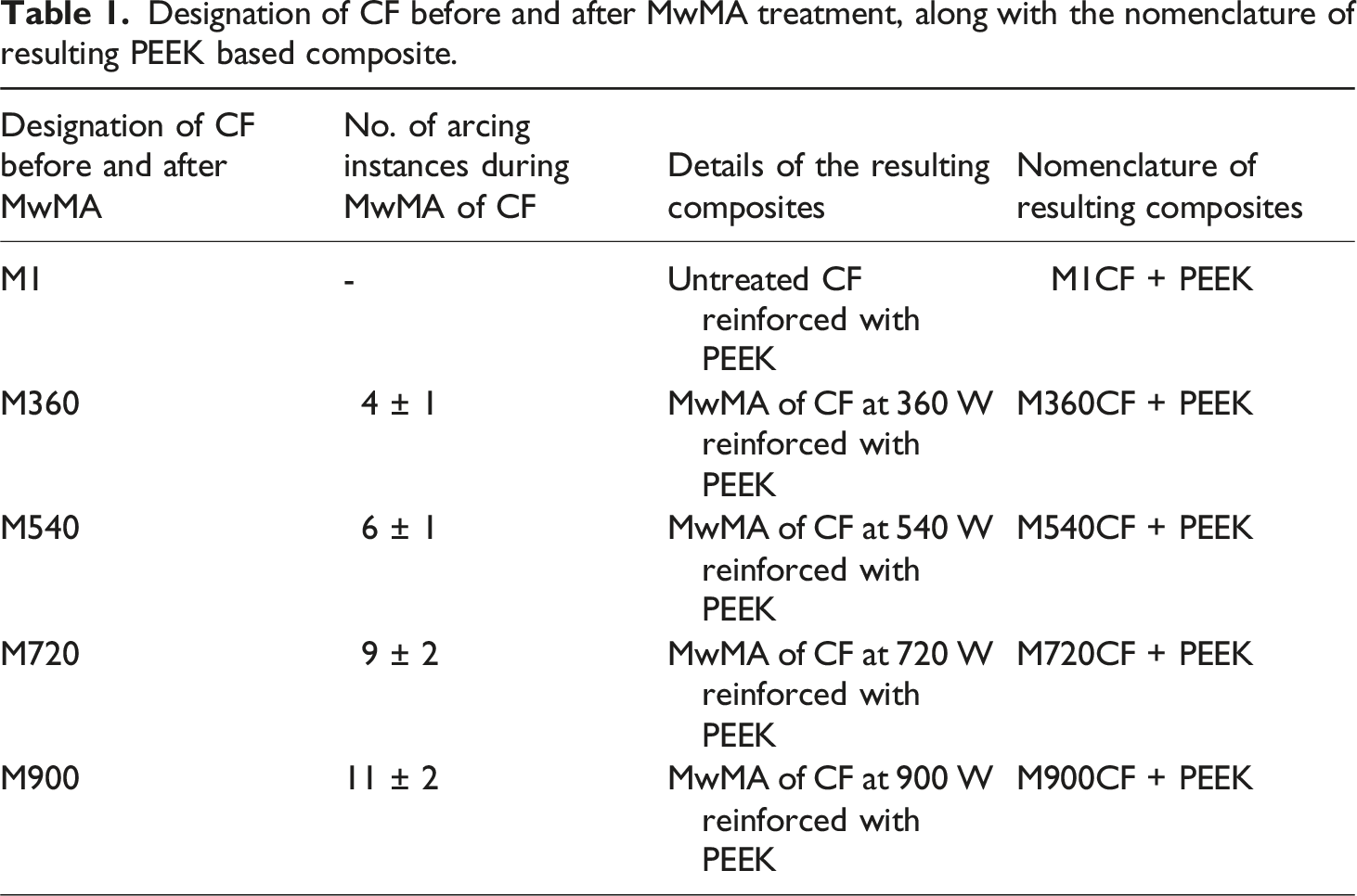
Designation of CF before and after MwMA treatment, along with the nomenclature of resulting PEEK based composite.
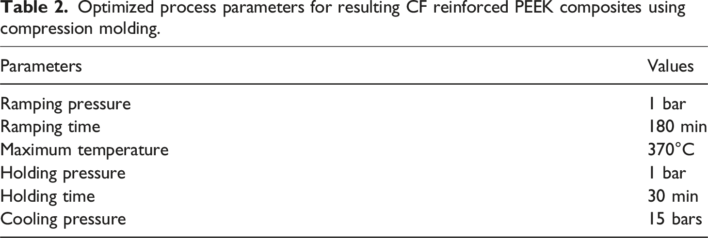
Optimized process parameters for resulting CF reinforced PEEK composites using compression molding.
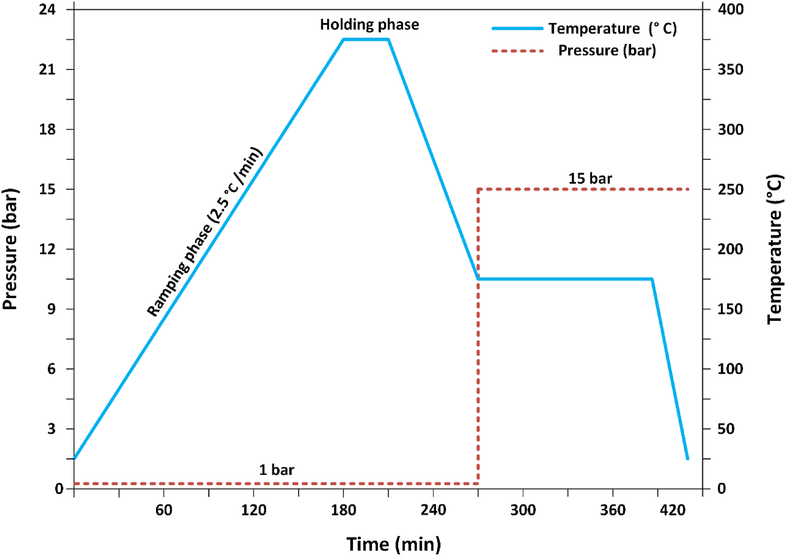
Pressure, temperature, and time profiles of the compression molding process for CF reinforced PEEK composites.
Surface characterization of CF
The surface morphology of engineered CF was studied using scanning electron microscopy (SEM) (Make: FEI, USA, Model: Nova Nano SEM 450). The accelerating voltage used during scanning electron microscopy was 10 kV, and the working distance was 4.8 mm. The wettability of the CF surface before and after MwMA was evaluated by contact angle using a contact angle instrument (Make: Surface & Electro-Optics Co. Ltd (SEO), Korea, and Model: SEO Phoenix 300). The surface roughness of CF were analyzed by atomic force microscopy (Make: Bruker, Model: Dimension ICON PT) with a scanning area of 3 microns × 3 microns in tapping mode. The element and chemical state of CF were analyzed by X-ray photoelectron spectroscopy (XPS) (Make: Thermo Scientific, Model: NEXSA Surface Analysis).
Mechanical properties of developed composite laminates
The mechanical properties of engineered CF resulting from PEEK composites were evaluated in terms of tensile strength, flexural strength, ILSS, and impact strength according to ASTM D3079, ASTM D790, ASTM D2344, and ASTM D256 standards, respectively.
4
Tensile and three-point bend tests were carried out on a Tinius Olsen H50 K testing machine of 50 kN capacity. The ILSS was done on universal testing machine with three-point bending fixture. The specimen was mounted on two cylindrical supports in 4:1 span to thickness ratio. The ILSS was then calculated using the following equation (3):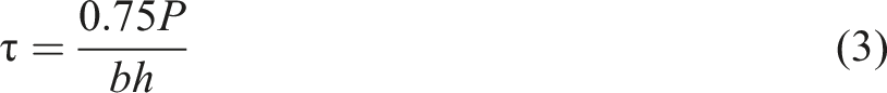
All the tests were conducted at a 1 mm/min strain rate to attain the quasi-static loading conditions. To ensure repeatability of test data, at least five specimens were tested in each case, and average values and errors in terms of standard deviation were reported.
Results and discussions
Surface morphology of CF
The SEM analysis was done on untreated CF specimens and MwMA engineered CF specimens. The SEM images showed the trend of increasing surface asperities with increased microwave power levels. Without MwMA, the surface of CF appeared smooth without any discontinuity, as seen in Figure 3(a). This uniform and smooth surface of carbon fiber renders poor adhesion to the PEEK matrix. Surface morphology of CF surface using SEM after MwMA as function of microwave power.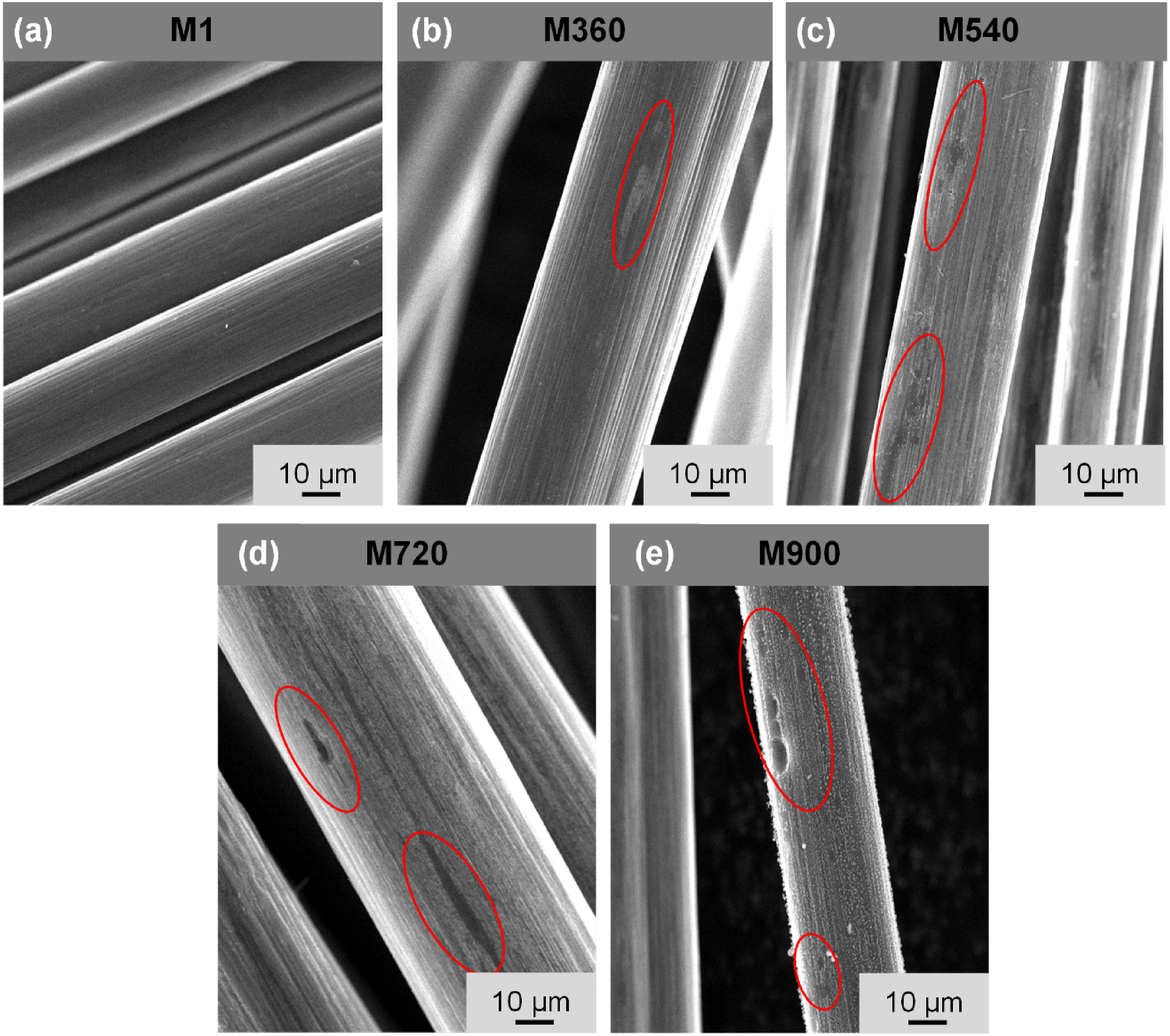
The MwMA conducted at microwave power levels of 360 W and 540 W, the surface alteration was observed as illustrated in Figure 3(b) and (c). At the power level of 360 W, on average, four arcing instances were observed, and at a power level of 540 W, six arcing instances were seen (Table 1). After each arcing instance, some part of the sizing material was removed, and surface roughness was observed in Figure 3(b) and (c). The roughness induced at these power levels causes improved interlocking of PEEK polymer with the CF. At the microwave power levels of 720 W and 900 W, the impact of MwMA was significant. A relatively more irregular surface with cracks was observed on the CF (Figure 3(d) and (e)). The number of arcing instances increased to approximately nine and 11 at 720 W and 900 W, respectively. As the number of arcing instances increased, more material was removed from the surface of the CF. An increased number of arcing instances at these higher levels of microwave even produced cracks in CF, as seen in Figure 3(d). Hence, as the microwave power level increased from 360 W to 900 W, the number of arcing instances increased (Table 1), and the number of instances of surface irregularities also increased (Figure 3).
Surface wetting characterization of CF
The contact angle method was employed to measure the changes in the wetting behavior of CF. The contact angle for untreated carbon fibers was 51.9° and wetting energy was 40.5 mN/m (Figure 4(a)). After MwMA of CF at different power levels, the contact angle was reduced by approximately 21%. It is known that low contact angles indicate a better degree of wettability of the CF surface.
29
The improvement in carbon fiber surface suggests that microwave treatment changes the surface properties of carbon fibers. Also, the wetting energy of the CF after MwMA increased by approximately 23%. Wetting or surface wetting energy indicates the interaction between liquid and solid phases.
28
The wetting energy and contact angle did not show any change (Figure 4(b)) at the microwave power level of 360 W, as evident from SEM images, less surface alteration in M360 specimens was observed (Figure 3(b)). From Figure 4(c), it can be seen that as the microwave power level increased to 540 W, the surface energy increased by 38%. Hence, more wetting was possible between CF and PEEK at this 540 W microwave power level. Further reduction in contact angle can be seen for the M720 and M900 CF specimen from Figure 4(d) and 4(e). At the power level of 900 W, the surface energy increased by 61% and the contact angle reduced to 32.5°. This indicates a higher wetting possibility of CF treated at a higher microwave power level. However, SEM micrographs (Figure 3(e)) show that at 900 W microwave power level, the number of surface irregularities and cracks increased. These surface irregularities and cracks improve the interfacial bonding but reduce CF surface area. The contact angle measurement of CF specimens showed that microwave exposure at a higher level improved the wetting behavior. Enhancement in the wettability can directly be associated with increased surface energy of engineered CF. Increasing trends in surface energy indicate more interaction between PEEK (in molten state) and CF. Hence, more wettability is possible at the higher MwMA CF reinforced PEEK composites. Surface wetting characterization of CF using contact angle measurement after MwMA as function of microwave power.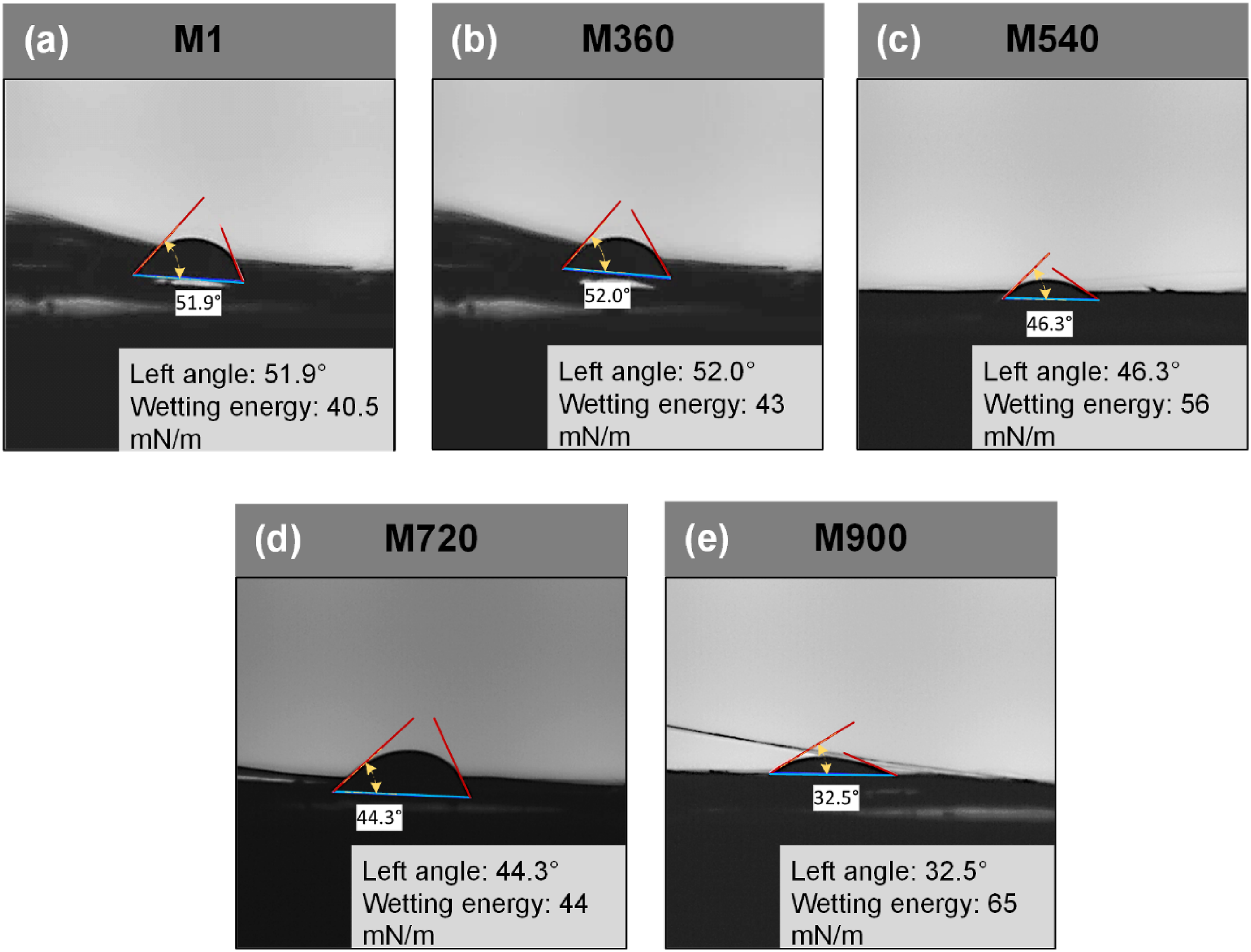
Surface roughness analysis of CF
The roughness induced by MwMA is quantified using average surface roughness (Ra) values of different CF specimens using an AFM. The Ra value indicates the average profile height value when measured from the mean line.
22
The Ra values and surface scans for different CF specimens are shown in Figure 5. The Ra value for the M1 CF specimen was found to be 6.02 nm, which suggests a relatively smooth surface with fewer peaks and valleys, as seen in Figure 5(a). The smooth surface of M1 CF causes insufficient interlocking of PEEK with CF. At the microwave power level of 360 W, the Ra value increased by 63%, which suggests a more irregular surface than M1 CF specimens Figure 5(b). The values of Ra changed to 71% and 72%, respectively, for M540 CF and M720 CF specimens (Figure 5(c) and (d)). As the number of arcing instances increased to six and nine for M540 and M720 CF, respectively, more sizing material was removed, as seen from SEM images (Figure 3(c) and (d)). As the MwMA level increased to 900 W, the value of Ra increased by 200% for the M900 CF specimen Figure 5(e). This surface roughness causes more interlocking with PEEK, but it reduces the effective cross-sectional area of carbon fibers. AFM scans showing surface roughness of CF before and after MwMA as function of microwave power.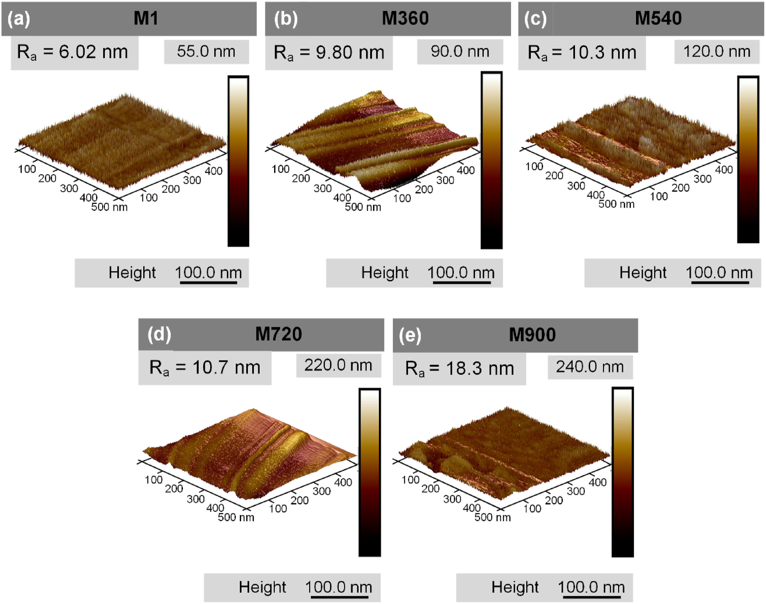
XPS analysis of CF
XPS was performed on carbon fibers specimens subjected to different microwave power levels (360 W, 540 W, 720 W, and 900 W), as well as an untreated carbon fiber specimen, to understand the effects of microwave treatment on the surface properties. The C 1s spectra of different samples are shown in Figure 6, with peaks showing presence of different functional groups. C 1s peak: The main peak nearly at 284 eV suggests the presence of carbon atoms in a sp2 hybridized state, which is the typical bonding configuration in carbon fibers. The shape and width of the peak can provide further information about the chemical state of the carbon atoms. C 1s peak fitting curves of carbon fiber: (a) M1, (b) M360, (c) M540, (d) M720, (e) M900 after MwMA as function of microwave power.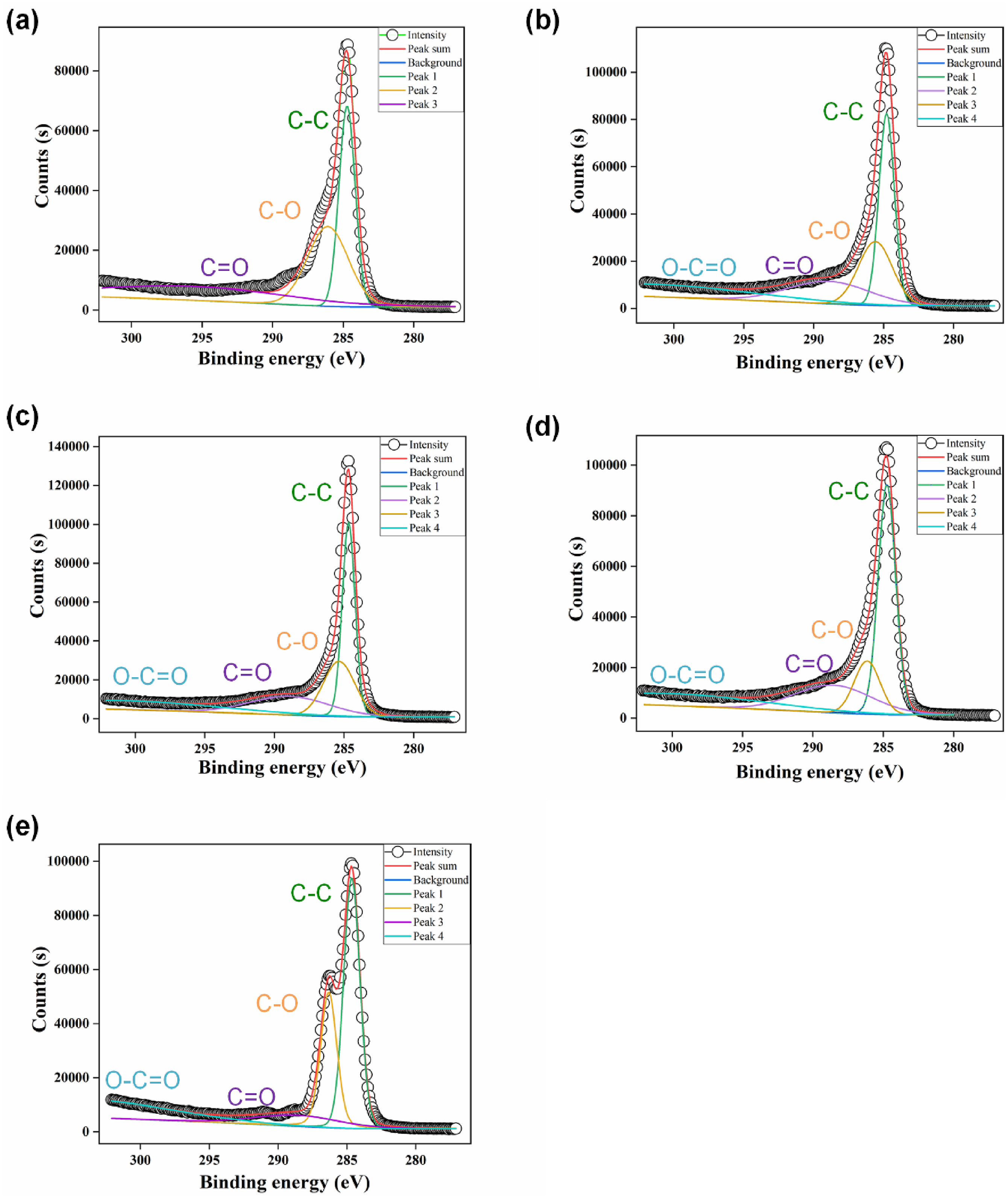
The C 1s spectra of all the carbon fiber specimens were deconvoluted into several components representing different chemical states of carbon. The C-C (sp2 hybridization) around 284.5 eV indicates the presence of graphitic carbon, the presence of C-O group around 286.0 eV shows the presence of hydroxyl or ether groups and presence of C = O around 288.5 eV indicates the carbonyl or carboxyl groups. 30 The C 1s spectrum of the untreated carbon fiber (M1) specimen (Figure 6(a)) shows the dominant peak at 284.5 eV corresponding to sp2 hybridization, with minor peaks corresponding to C-O and C = O groups. For the carbon fiber treated at 360 W (M360), there is increment in the intensity of the C-O peak compared to M1 CF carbon fiber specimens (Figure 6(b)). This increment in peak suggests the microwave treatment at 360 W introduces additional ether groups on the surface of carbon fiber and helps in improve the CF/PEEK bonding. The C 1 s spectrum for M540 (Figure 6(c)) shows the highest intensity of C-O peak among all MwMAed CF specimens, indicating the significant presence of ether groups over the surface of carbon fibers. The C = O peaks also increases (Figure 6(c)), this suggest the formation of carboxyl groups. The surface functionalization is likely responsible for proper wetting of carbon fiber (Figure 6(c)). The MwMAed CF specimens at 720 W (M720) shows reduction in the C-O peak intensity compared to 540 W treated fiber (Figure 6(d)). The C = O peak remains prevails, indicates the surface oxidation and some surface damage at this microwave power levels. For the carbon fiber treated at 900 W (M900), both the C-O and C = O peaks were significantly reduced (Figure 6(e)). This suggest that at microwave power level of 900 W causes thermal degradation of surface of carbon fibers leading to reduction in mechanical properties of developed composites.
Mechanical characterization of developed composites
The uniaxial tensile strength of the PEEK-based resulting composites containing reinforcement as untreated CF and MwMAed CF at various microwave power levels is shown in Figure 7(a). It can be observed that the maximum increment in tensile strength of the resulting CF reinforced PEEK composites (M540CF + PEEK) was nearly 22% compared to untreated CF reinforced PEEK composites (M1CF + PEEK). As illustrated in Figure 3, the MwMA of CF increased the wetting energy by 23% and reduced the contact angle by 21%. This improves the adhesion between MwMAed CF and PEEK. The Ra value was 6.02 nm for M1 CF. Due to insufficient interfacial bonding and interlocking, the load did not transfer effectively from PEEK to M1, and tensile strength was observed to be approximately 128 ± 3.5 MPa. Subsequent carbon fiber treatments at the microwave power level of 360 W and 540 W caused further improvement in tensile strength (Figure 7(a)) due to higher surface energy and better matrix locking around the fibers. As the microwave power level increased to 720 W and 900 W, the tensile strength of M720CF + PEEK and M900CF + PEEK composite specimens reduced by around 5% and 16%, respectively from its maximum value at M540CF + PEEK composite specimen. At the microwave power level of 900 W, the wetting energy increased to 65 mN/m, and the contact angle was reduced to 32.5° (Figure 4(e)). However, for M720 and M900, more surface damage and cracks were seen in SEM (Figure 3(d) and (e)) which resulted in a reduced effective cross-sectional area of M720 and M900. (a) Tensile strength, (b) Flexural strength, (c) Interlaminar shear strength, (d) Impact strength of CF reinforced PEEK composites after MwMA as function of microwave power.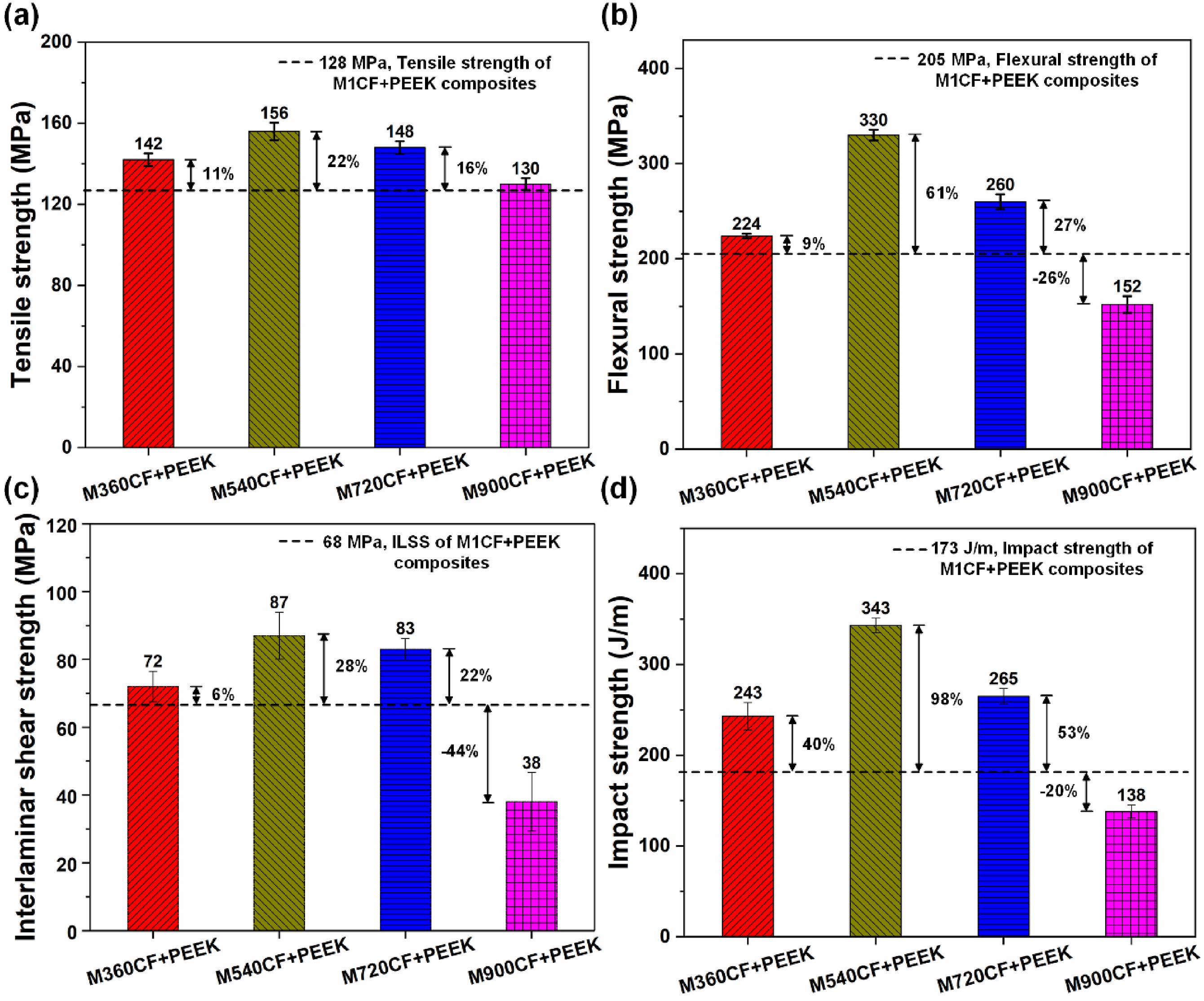
The flexural strength of the PEEK-based resulting composites containing reinforcement as untreated CF and MwMAed CF at various microwave power levels is shown in Figure 7(b). It can be observed from Figure 7(b) that the maximum increment in flexural strength of the M540CF + PEEK specimen was near to 61% compared to M1CF + PEEK. The flexural strength for the M360CF + PEEK specimens shows increments of around 9%. As illustrated in Figure 8(a) and (b), the number of fiber and matrix debonding sites at the compression side was seen due to smooth surface and low wetting energy (Figure 4(a)). For M540 CF, the surface energy of CF reached to 56 mN/m Figure 4(c)); hence, more wetting of CF was possible, and surface roughness induced by MwMA caused proper interlocking of PEEK around the CF. Thus, less number of fiber and matrix debonding sites were seen, as illustrated in Figure 8(c). After reaching peak flexural strength values for M540CF + PEEK composite specimens, the flexural strength started to reduce in the case of M720CF + PEEK and M900CF + PEEK composite specimens due to more surface roughness at higher levels (Figure 5(d) and (e)). As illustrated in Figure 8(d) and (e), fiber number of fracture sites increased at the tensile side of the composite due to the increased surface roughness (Figure 5(d) and (e)). Although, the wetting energy also increased in the M900 specimen (Figure 4(e)), which improved interfacial adhesion. An increase in surface roughness increased the stress concentration site in the CF, and fiber fracture was seen in several instances (Figure 8(d) and (e)). Hence, flexural strength is reduced at microwave power levels of 720 W and 900 W to 260 ± 7.8 MPa and 152 ± 8.7 MPa, respectively. Failure mechanism in CF reinforced PEEK composites in flexural loading for various composite laminates shown from (a) to (e), SEM images of flexural fractured surface of CF reinforced PEEK composites: (f) M1CF + PEEK, (g) M360CF + PEEK, (h) M540CF + PEEK, (i) M720CF + PEEK, (j) M900CF + PEEK after MwMA.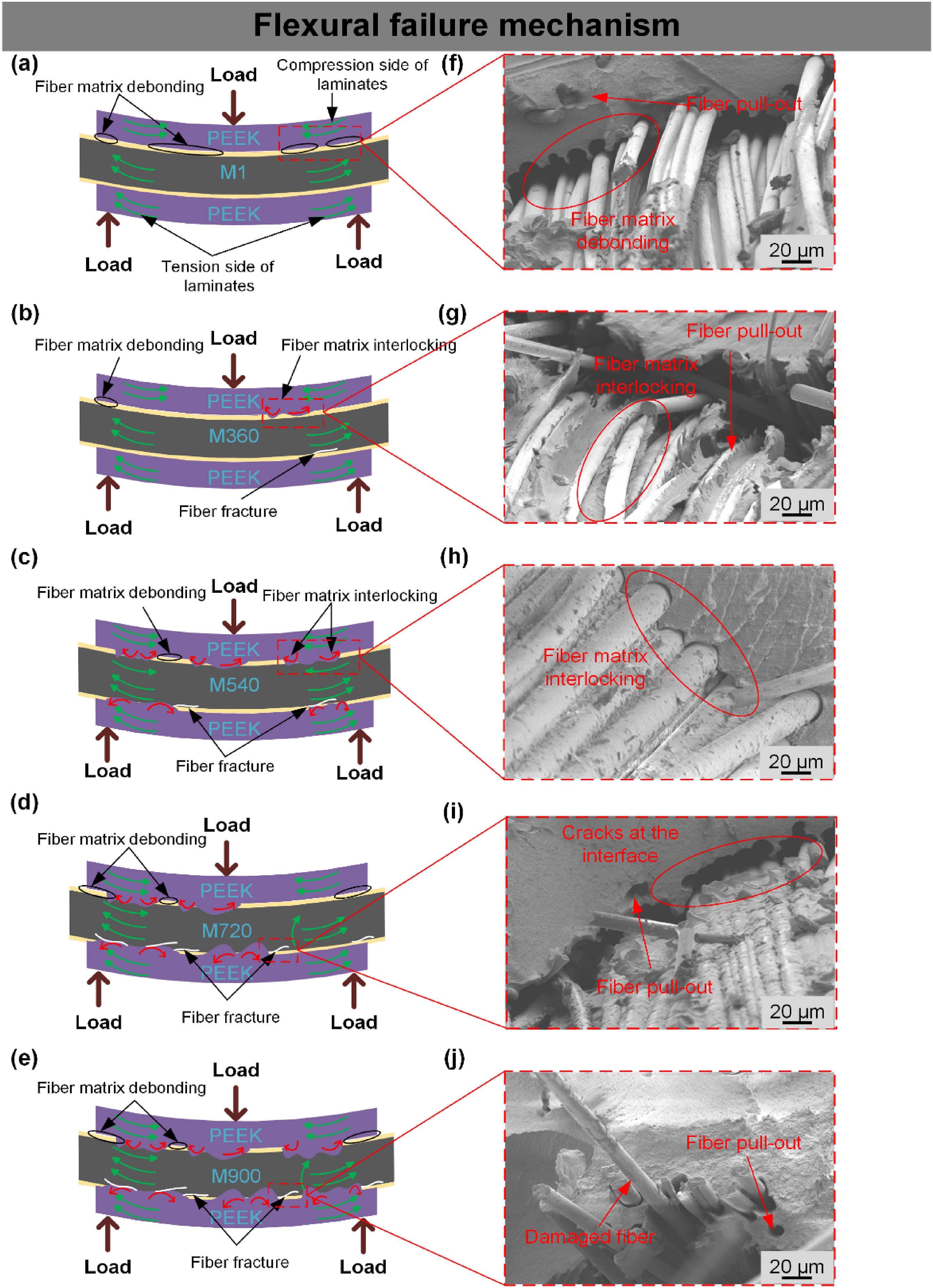
The ILSS values of the carbon fiber reinforced PEEK composites show similar variation as in case of flexural testing .The untreated composite specimens (M1CF + PEEK) exhibited an ILSS of 68 ± 3.8 MPa as illustrated in Figure 7(c). The ILSS increased by approximately 6% for M360CF + PEEK composite specimens. The use of a higher microwave power level (540 W) for M540CF + PEEK composite specimens led to considerable improvement in ILSS until 87 MPa. This suggest that MwMA is the optimal level of microwave power level MwMA. On increasing the microwave power to 720 W, the ILSS was slightly reduced to 83 ± 3.2 MPa, this value of ILSS still higher that of M1CF + PEEK composite specimens by nearly 22%. This indicates the excess microwave power level could be impairing the fiber and matrix interface and leading to reduction in ILSS. At the microwave power level of 900 W, the ILSS of M900CF + PEEK specimen drastically reduced to 38 MPa, which was nearly 44% less than that of M1CF + PEEK composite specimens. This significant reduction in ILSS at higher level of 900 W suggest that higher microwave power incurs the damage to carbon fiber surface and reduction in ILSS.
The impact strength results (Figure 7(d)) show effect of MwMA on the surface of carbon fibers. At the microwave power level of 360 W, the composite specimen of M360CF + PEEK shows the impact strength nearly 40% higher than the M1CF + PEEK composite specimen. The improved impact strength suggests the enhanced energy absorption capability of M360CF + PEEK composite specimens. As the microwave power level increased to 540 W for M540CF + PEEK composite specimens the impact strength increased approximately by 98%. The improvement in impact strength happens due to proper adhesion of carbon fiber and PEEK polymer and hence energy is uniformly distributed within the composites and impact strength improved. The MwMA at 720 W, the impact strength slightly reduced to 265 ± 8.5 J/m for M720CF + PEEK composite specimens. Still, the impact strength of M720CF + PEEK higher than untreated composites (M1CF + PEEK) by nearly 53%. At the higher microwave power level of 900 W, the composite specimens (M900CF + PEEK) showed the reduced impact strength of 138 ± 7.3 J/m which was nearly 20% less than M1CF + PEEK composite specimens. This dropped impact strength of composite specimens suggests the poor energy absorbing capabilities. At the higher microwave power level (<720 W, 900 W), the SEM scans (Figure 3(d) and (e)) suggests the micro cracks sites were more in M720 and M900. Hence this reduced effective surface area of carbon fiber caused reduction in impact strength for M900CF + PEEK composites specimens.
The decline in tensile strength, flexural strength, ILSS, and impact strength could be attributed to damage induced at higher microwave power levels (<720 W, 900 W), due to the increased number of arcing instances that damaged the surface of CF. Hence, the current investigation suggests a trade-off between wetting or adhesion of CF|PEEK and mechanical behavior. The 540 W microwave power level gives the optimized behavior in both wetting characteristics and mechanical strength.
The finding suggests that MwMA treatment of carbon fibers at the microwave power level of 540 W optimally enhance tensile, flexural, ILSS, and impact strength of M540CF + PEEK composite specimens. The enhanced mechanical properties of composites specimens due to better surface locking (Figure 3(c)), surface wettability of carbon fibers (Figure 4(c)) and better surface roughness (Figure 5(c)). This promotes proper interlocking the PEEK polymer over the surface of carbon fibers.
Fractured surface analysis of developed composites using SEM
The fractured surface morphologies of MwMA treated and untreated CF reinforced PEEK composites were shown in Figure 8(f)–(j). The composite specimens MICF + PEEK shows PEEK did not wet the CF properly (Figure 8(f)), and more debonding and fiber pullout sites. Hence load does not get transferred effectively from PEEK to CF and caused lower mechanical strength (Figure 7). As the microwave power increased to 360 W and 540 W more PEEK adhered to the surface of M360CF + PEEK and M540CF + PEEK (Figure 8(g) and (h)) as wettability increased for M360 and M540 CF (Figure 4(b) and (c)). The proper adhesion and interlocking of PEEK around CF provide best mechanical properties for M540CF + PEEK (Figure 7). As MwMA at 720 W and 900 W increased the wettability (Figure 4) and strong presence of hydroxyl and carboxyl group (Figure 6), hence more PEEK adhered to surface of CF (Figure 8(i) and (j)) but due to roughness induced by MwMA, the fractured surface shows the surface irregularities over M720CF + PEEK and M900CF + PEEK. Hence more cracks were seen for M720CF + PEEK and M900CF + PEEK. Due to the more surface roughness on M720 and M900 (Figure 5(d) and (e)), fiber breaks easily for M720CF + PEEK and M900CF + PEEK (Figure 8(i) and (j)) laminates. The damaged CF at 900 W caused lowest mechanical properties in M900CF + PEEK composite laminates (Figure 7).
Conclusions
The MwMA on CF has demonstrated a promising route to improve interfacial bonding between CF and PEEK matrix, thereby enhancing the mechanical properties of resulting composites. The MwMA on CF at 540 W for 60 s induces the optimal surface roughness to improve the overall mechanical properties of resulting PEEK-based composites. Furthermore, SEM and AFM results suggested that MwMA at higher power levels deteriorates the surface of CF and reduces the mechanical properties of resulting PEEK-based composites. XPS analysis further shows that MwMA introduces the C-O and C = O functional groups, which helps in enhancing the CF and PEEK interfacial bonding. Hence, it can be concluded that microwave micro arcing (MwMA) at optimum power level offers the potential for surface modification and enhanced interfacial between the PEEK matrix and carbon fibers. Further studies can investigate the effect of MwMA on the fatigue properties of CF reinforced PEEK composites.
Footnotes
Declaration of conflicting interests
The author(s) declared no potential conflicts of interest with respect to the research, authorship, and/or publication of this article.
Funding
The author(s) received no financial support for the research, authorship, and/or publication of this article.