
Abstract
This paper presents a comprehensive assessment of the effect of bolt size and fibre orientation on the bearing performance and damage mechanisms of single-bolt double-shear (SBDS) lap joints in 3D fibre-reinforced composites (FRC). The bearing performance of resin-infused thermoplastic 3D-FRC was evaluated along the on-axis (0° and 90°) and off-axis (45°) fibre orientations and compared with their thermoset counterparts. The resin-infused thermoplastic 3D-FRC joints exhibit superior bearing performance in terms of absorbed energy, bearing stiffness, ultimate bearing strength, and damage severity. In on-axis configurations, as the bolt size increases the bearing strength decreased by 26% and 21%, whereas the bearing stiffness increased by 46% and 48% in thermoset and thermoplastic 3D-FRC, respectively. In off-axis configuration, thermoplastic lap joints experience a significant increase of 116% in the bearing stiffness with a slight decrease of 12% in the bearing strength, while thermoset joints exhibit an increase of 21% in bearing stiffness with a reduction of 25% in bearing strength. Furthermore, the surface morphology of damaged specimens showed the main damage characteristics of thermoplastic bolted joints include plastic kinking while the damage characteristics of thermoset include undesirable damage modes, i.e., fibre/matrix debonding, transverse cracking and fibre brooming.
Keywords
Introduction
Nowadays, fibre-reinforced composites (FRC) are widely used as a structural material in various engineering applications, such as aerospace, automotive, construction industries, etc. The FRC structures are commonly assembled by joining several composite parts together. 1 For reliable structural applications of FRC, the use of suitable joining techniques and reinforcement (2D-FRC or 3D-FRC) is essential for providing safe load transfer mechanisms and superior joint efficiency.2,3 The 3D-FRC provides the benefit of producing near-net-shaped designs, making it possible to produce complex-shaped parts by reducing the number of joints. Despite these benefits, it does not deny the need for joints in 3D-FRC structures, due to limitations on the component size.4,5 During the last two decades, extensive research has been conducted on the joints, however, the effect of matrix toughness on the bearing performance of bolted joints in 3D-FRCs has not been sufficiently discussed and needs further research to achieve scientific maturity.
There are three main types of joints in FRC structures, i.e., mechanically fastened, adhesive bonded, and hybrid joints.6–10 The mechanically fastened joints and adhesive-bonded joints are the most common joining techniques used in composite structures.11,12 The adhesive joints have several benefits, such as simple bonding, less weight, and good shear load transfer. However, inconsistent bonding can lead to cracking or debonding, increasing the risk of structural failure without being detected throughout the lifespan.13–17 Bolted joints, on the other hand, provide higher safety, reliability, and load transfer efficiency in addition to ease of disassembly for repair. Therefore, bolted joints are typically favoured in industrial applications including the aerospace industry.18–20 The bolted joint is further classified into a single-shear and a double-shear configuration, each having its own set of advantages and disadvantages. Despite the easy installation of single shear configuration, the double-shear configuration is preferred because it does not undergo out-of-plane deformation, which is undesirable and adversely affects the bearing performance of the joint. 21
The joint performance and failure modes depend on several factors such as pre-torque, bolt hole clearance, bolt type, geometric ratios (specimen width w to hole diameter D ratio w/D, edge distance e to hole diameter D ratio e/D, thickness), and material anisotropy.22–25 In bolted joints, FRCs fail in three main modes, i.e., net-section tensile failure, shear-out failure, and bearing failure. The net-tensile failure occurs in small width joints, whereas shear-out failure mainly appears with small edge distance. Both failure modes are undesirable and affect the overall structural performance. Bearing is a desirable failure mode it occurs when e/D and w/D are high. As a result, the hole gradually elongates along the loading direction due to the crushing of the material and provides forewarning prior to the complete failure. Several researchers have analysed the bearing performance of bolted joints in FRCs.7,26–29 In bolted joints, damage typically propagates through holes, which are regarded as a weak zone due to high-stress concentration at the interaction point between the bolt and the hole.30–34 Yoon et al. 2 evaluated the e/D ratio of prepreg carbon/epoxy SBDS lap joints to induce the bearing failure modes. The authors revealed that 2% offset bearing strength remained constant until e/D ≥ 3, whereas for e/D ≤ 3 a significant increase in bearing strength was observed. Othman and Jadee 35 studied the load-bearing capacity of E-glass/epoxy with varied e/D and w/D ratios. The authors concluded that large geometric parameters yield higher bolt-hole elongation and bearing strength. Furthermore, laminates with large geometric parameters resulted in bearing failure, while laminates with smaller geometric parameters experienced catastrophic net-tensile or shear-out failure. Similarly, Zhang et al. 36 studied the influence of e/D and w/D in pin-loaded carbon/epoxy 3D-FRC. The study revealed that the specimens failed due to net tension or shear-out failure depending on the e/D and w/D ratios. Warren et al. 37 investigated the bearing failure of 3D-FRC in single-shear and double-shear configurations. The authors reported that 3D-FRC improves the load-carrying capacity of joints and exhibits exceptional strength when subjected to off-axis bearing loads.
The above literature reveals that a few researchers have investigated the bearing performance of SBDS lap joints in thermoset-based FRC.36,38–42 To the best of the author’s knowledge, no study has been carried out on the bearing performance of resin-infused thermoplastic 3D-FRC in SBDS lap joint configurations. In addition, there is a lack of understanding of the effect of matrix toughness, bolt diameter, and fibre orientation on the failure modes of 3D-FRC in SBDS lap joints. The matrix toughness plays a vital role in improving the bearing performance of double shear bolted joints by reducing the damage severity and stress concentration around the bolt hole and improving crack propagation resistance and load distribution. Therefore, such a study is imperative to improve our understanding on the bearing performance and failure modes of 3D-FRC in SBDS lap joints, which will assist the design and development of sustainable resin-infused thermoplastic composite structures for various applications.
The aim of this study is to investigate the bearing performance of 3D-FRC in SBDS lap joints. First, the bearing performance (strength, stiffness, energy absorption, damage severity, etc.) of resin-infused thermoplastic 3D-FRC was evaluated using SBDS lap joints tests. Second, to assess the effect of matrix toughness, the bearing performance of resin-infused thermoplastic 3D-FRC was compared with equivalent thermoset 3D-FRC. Third, to understand the effect of bolt diameter on the bearing performance of 3D-FRC, three different bolt sizes, i.e., 4 mm, 6 mm, and 8 mm were considered. A constant w/D ratio was used in all cases to eliminate size-effect on joints. Fourth, to evaluate the effect of fibre orientation on the bearing performance on 3D-FRC, a detailed comparison of on-axis (0° and 90°) and off-axis (45°) configurations are presented. Lastly, to establish the effect of matrix toughness, bolt diameter, and fibre orientation on the failure modes of 3D-FRC, a comprehensive fractographic investigation of the failure surfaces was carried out using scanning electron microscopy (SEM).
Materials and methods
Materials
Properties of Elium® and Epolam®.
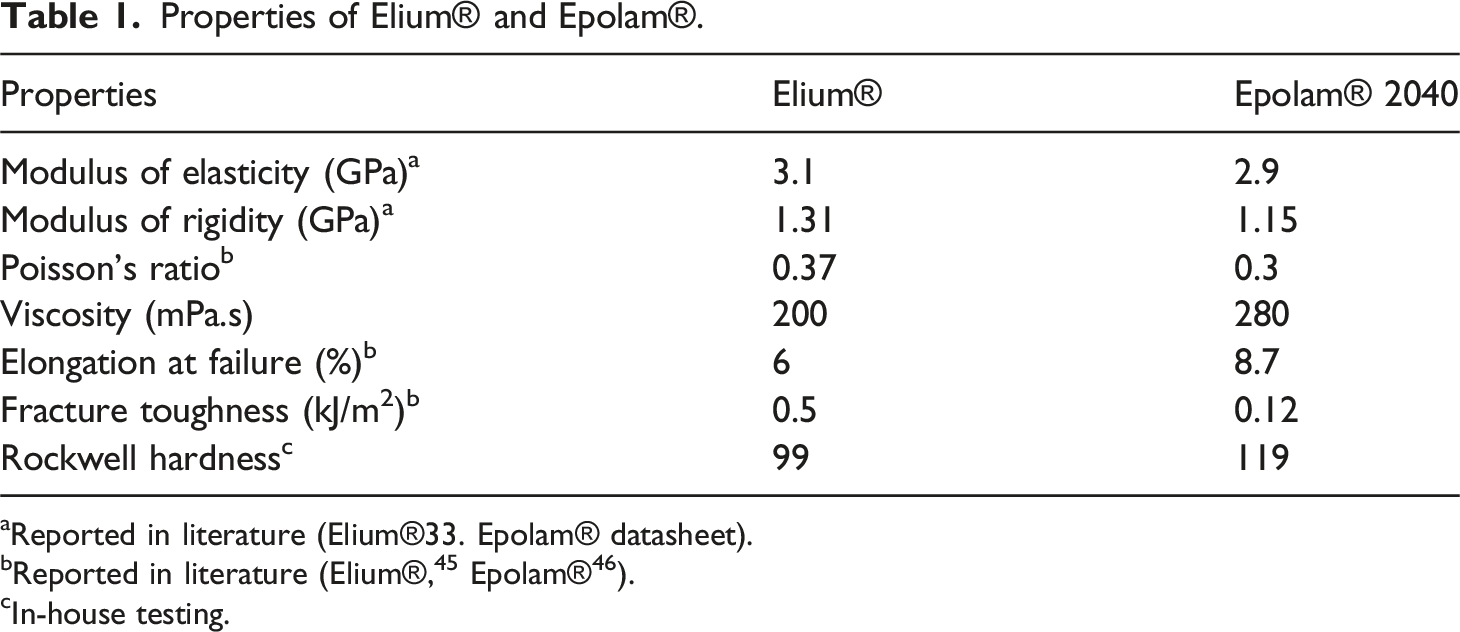
aReported in literature (Elium®33. Epolam® datasheet).
cIn-house testing.
Fabrication of 3D-FRC
Average mechanical properties and physical parameters of thermoplastic and thermoset 3D-FRC.
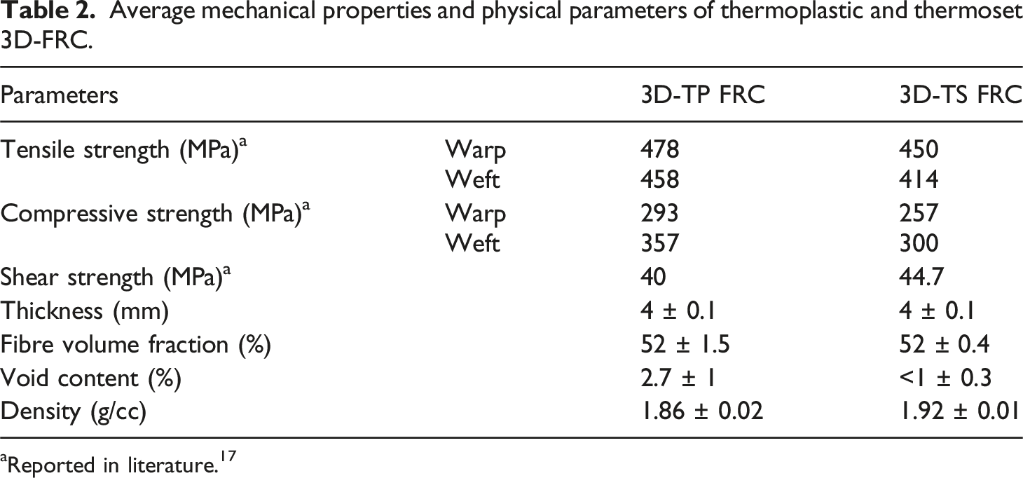
aReported in literature. 17
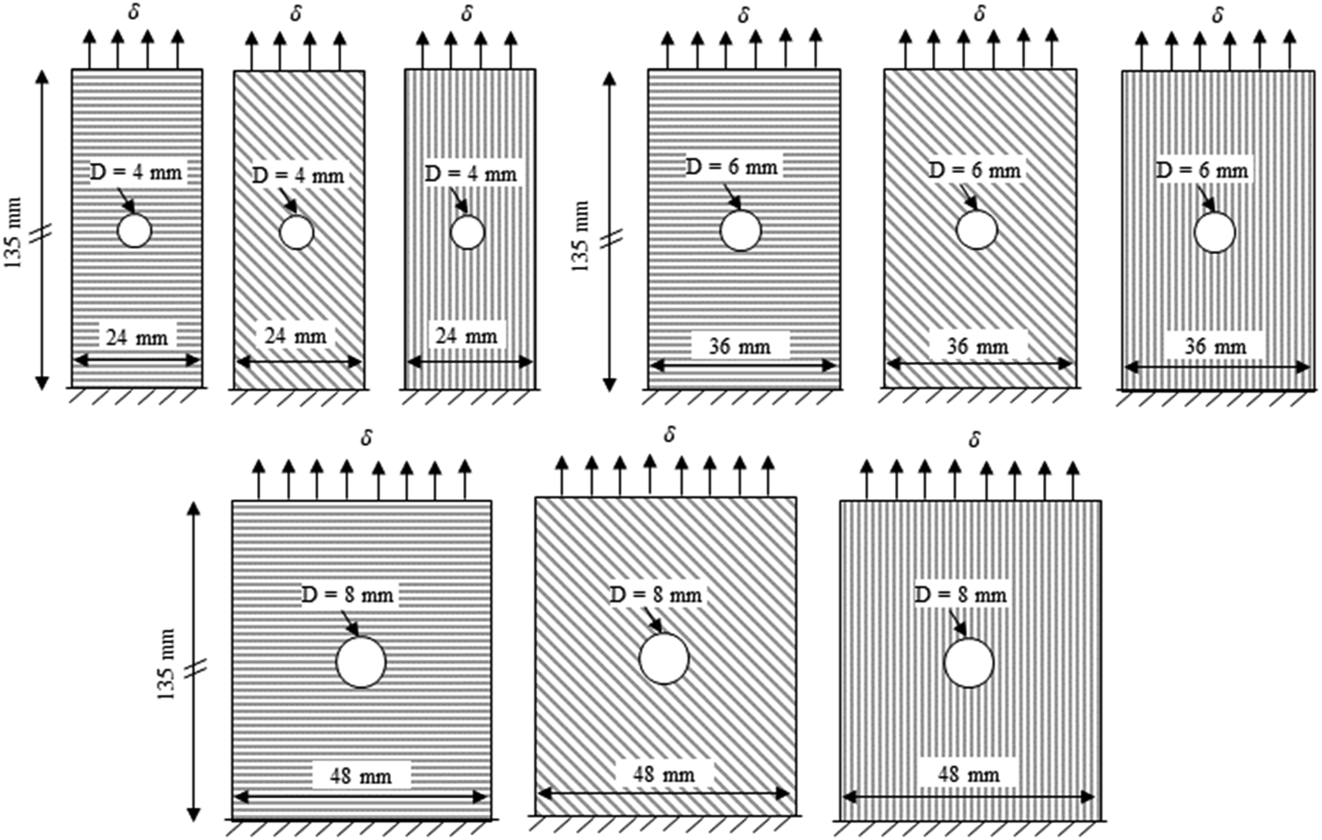
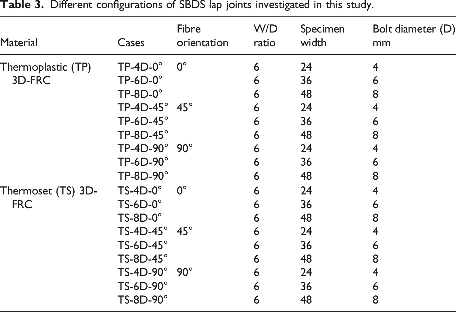
Schematic diagram of different configurations of SBDS lap joints investigated in this study.
Bearing test
In this study, double shear bearing tests were performed using a Zwick/Roell® universal testing machine, which is equipped with a 100 kN load cell. The tests were performed at a constant load rate of 2 mm/min, as per ASTM standard D5961/5961M-13 procedure A, 47 which is extensively employed to evaluate the performance of bolted joints. In all experiments, a constant width w to hole diameter D ratio, i.e., w/D = 6, and the edge distance e to hole diameter D ratio, i.e., e/D = 3 were used, as recommended by the ASTM standard D5961/5961M-13. 47 All the samples were drilled at a constant feed rate and spindle speed of 2 mm/min and 6000 r/min, respectively, using a silicon carbide drill bit. It is well-known that the drilling operation may induce delamination in FRC. To minimize the delamination during the drilling operation, a backup support method was employed. This involved placing the sample temporarily clamped between two plates made of the same material before the drilling commenced. The overall dimensions of specimens for the SBDS lap joint are 135 mm x (6 × D) as shown in Figure 1. The samples were mechanically fastened with hexagonal socket head steel bolts (M4, M6, and M8, Grade 12.9), and steel washers (M4, M6, and M8, Grade 12.9) with an outer diameter of 8 mm, 12 mm, and 15 mm, respectively. A torque of 6 Nm was applied to all the SBDS joints as recommended by the ASTM standard D5961-5961M-13. 47
A customized fixture was designed and fabricated in-house to evaluate the bearing performance of single-bolt double shear lap joints with different bolt sizes. Figure 2(a) shows the schematic diagram of the fixture along with its dimensions. Figure 2(b) shows the schematic diagram of single bolt double shear lap joint configuration, along with geometric parameters. In all configurations, a constant overlapped region of 6D was used. Two stainless washers were used on each side of the specimens, to maintain a constant gap between the specimen and the fixture, as shown in Figure 2(b). Figure 2(c) shows the schematic diagram of the specimen loaded in UTM, whereas Figure 2(d) shows the actual testing configuration. To prevent delamination caused by drilling process preventive measures were taken, as discussed earlier. The effectiveness of these measures was validated by examining a cross-section of the drilled hole using SEM, as shown in Figure 2(f). No delamination was observed in the sample due to drilling process. The bolt diameter, hole tolerances and clearance were used according to ASTM standard D5961/5961M-13.
47
The different configurations investigated in this study are summarized in Table 3. A total of 54 test samples were prepared, 27 samples each for resin-infused thermoplastic and thermoset 3D-FRC. Three repeats were performed for each configuration investigated in this study. SBDS lap joint test configuration. (a) Schematic diagram of fixture fabricated for SBDS testing, (b) Schematic diagram of SBDS lap joint with parameters, (c) Schematic diagram of test sample placement in UTM, (d) experimental setup for bearing testing, (e) selected bearing plane for SEM investigation, and (f) drilled hole cross-section SEM. Different configurations of SBDS lap joints investigated in this study.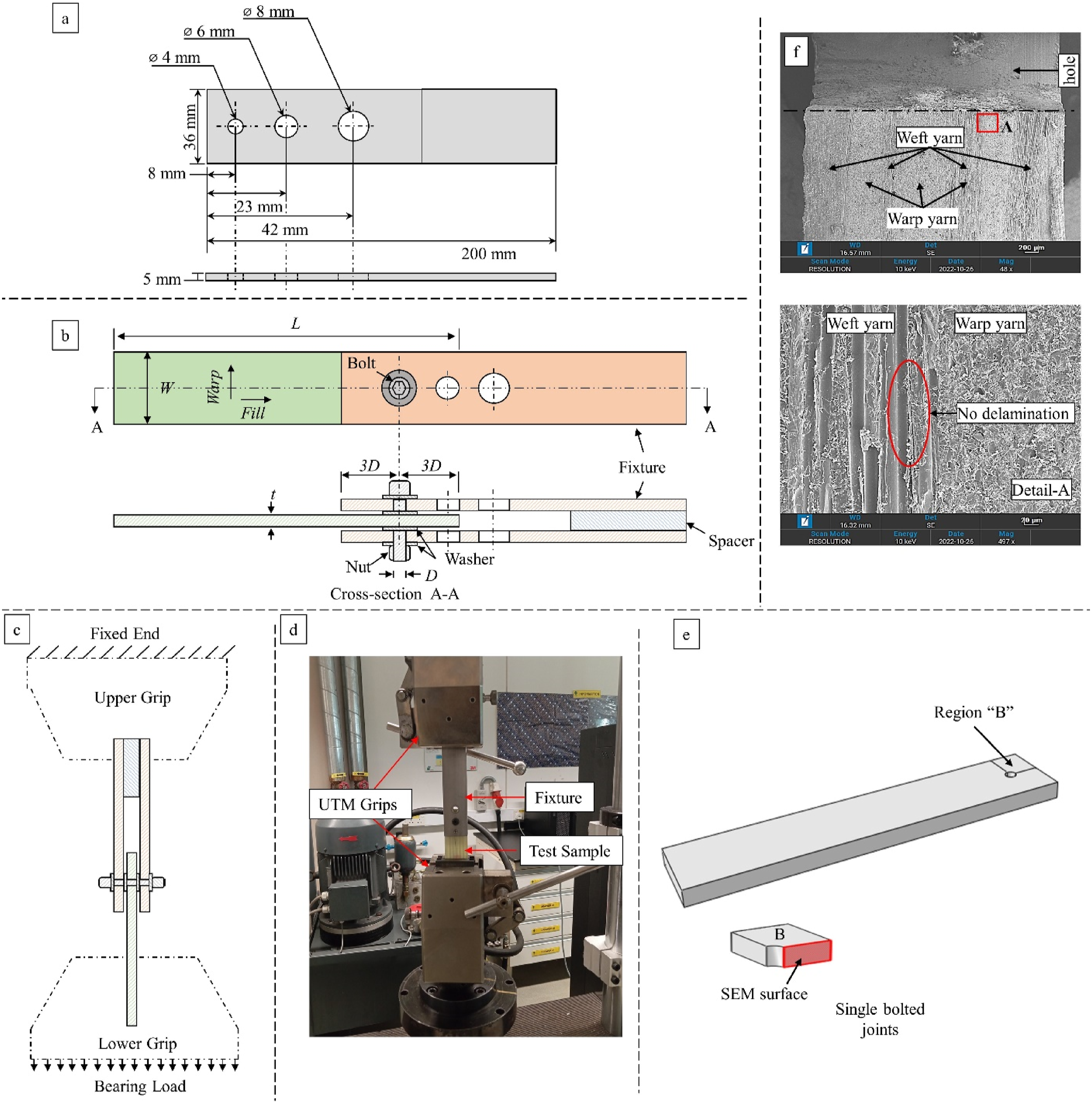
Fractography
The final damaged states of 3D-FRC samples were investigated using scanning electron microscopy (SEM) with the ZEISS-SUPRA 40 VP SEM machine. The damaged samples were cut by using a water-based diamond wheel precision saw at the middle plane of the joint i.e., Region B, as shown in Figure 2(e). The cross-sectional specimens were initially polished using a Phoenix 4000 polisher/grinder to get high-resolution SEM pictures followed by a coating of 40 nm gold covering to improve conductivity.
Evaluation method
The bearing performance of 3D-FRC under SBDS was evaluated in terms of failure initiation load 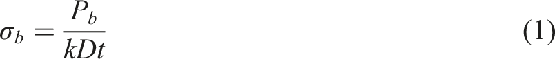
Results and discussion
Bearing performance of double shear lap joint
This section presents the bearing performance of resin-infused thermoplastic and thermoset 3D-FRCs under a single-bolt double-shear test. The load vs. displacement, failure initiation and final loads, bearing stiffness, bearing strength, and energy absorption responses of resin-infused thermoplastic 3D-FRCs were evaluated and compared with thermoset 3D-FRCs.
Comparison of load versus displacement response
The load/displacement curves of the resin-infused thermoplastic and thermoset 3D-FRCs obtained from the SBDS lap joint test are shown in Figure 3. The curves obtained from the three sets of samples for each configuration showed good agreement and provided comprehensive detail on the bearing performance of 3D-FRCs. Both resin-infused thermoplastic and thermoset 3D-FRCs exhibited a linear-elastic response until the failure initiation point, followed by a nonlinear shear behaviour at a higher bearing load Load versus displacement curves of single bolt double shear lap joint configuration. (a) and (c) On-axis thermoplastic SBDS lap joint configuration, i.e., (0°) and (90°), (c) Off-axis thermoplastic SBDS lap joint configuration (45°), (d) and (f) On-axis thermoset SBDS lap joint configuration, i.e., (0°) and (90°), (c) Off-axis thermoset SBDS lap joint configuration (45°).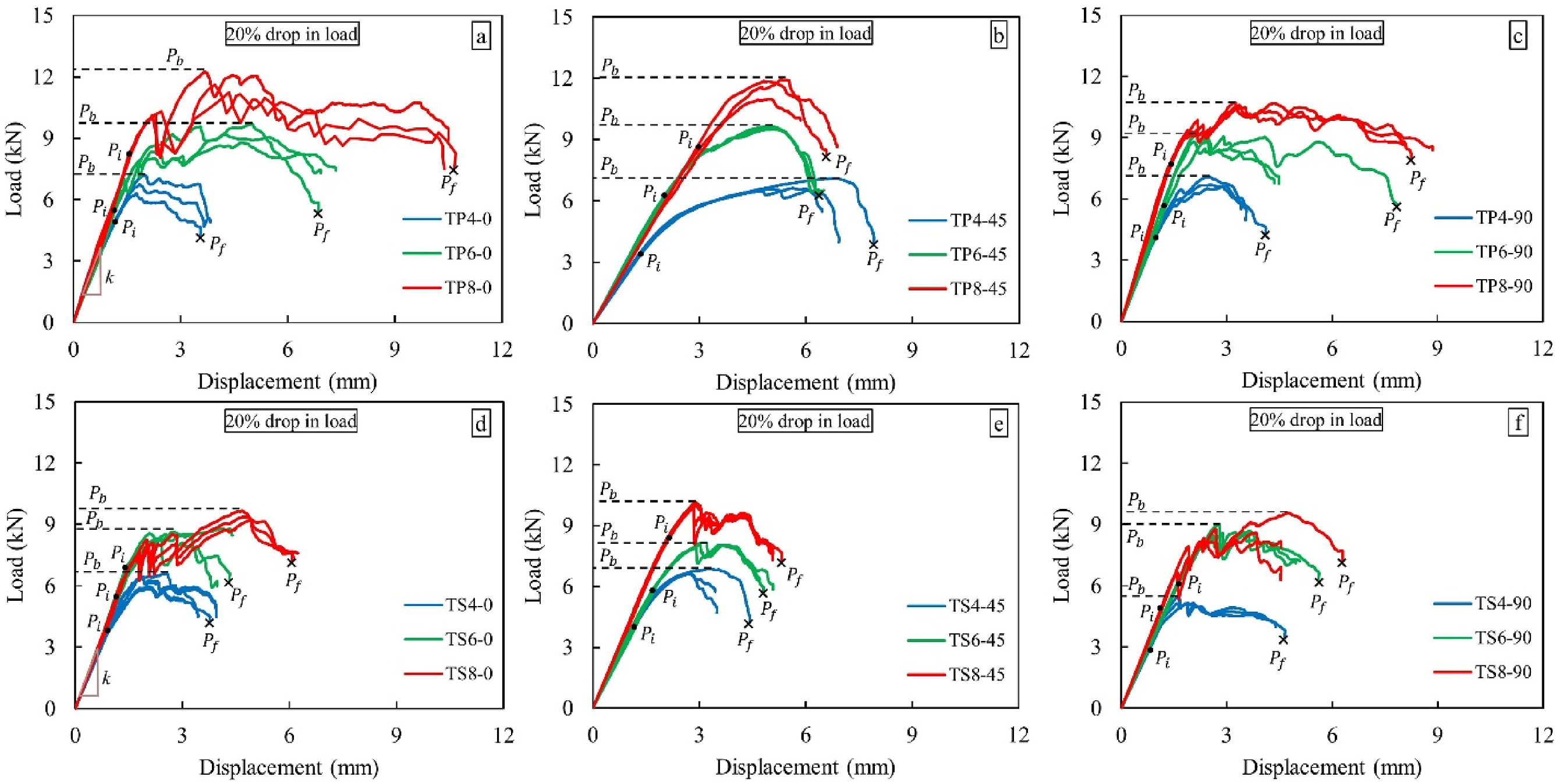
The load/displacement curves are categorized into on-axis and off-axis configurations, as shown in Figure 3(a)–(f). In on-axis configuration, resin-infused thermoplastic 3D-FRCs show similar bearing strength and peak load due to the same weight percentage of fibres and higher matrix toughness, as illustrated in Figure 3(a) and (c). In contrast, despite having same fibre contents, thermoset 3D-FRCs showed slight variation in the bearing response of the SBDS lap joints owing to their lower matrix toughness, as shown in Figure 3(d) and (f). The lower matrix toughness leads to damages such as transverse matrix cracking, fibre/matrix debonding, fibre brooming, and buckling of load-bearing yarns, which consequently reduces the bearing performance of thermoset joints. In off-axis configuration, resin-infused thermoplastic lap joints exhibit higher bearing loads and displacement compared to thermoset counterparts, as shown in Figure 3(b) and (e). This enhanced performance of resin-infused thermoplastic 3D-FRCs can be attributed to the stronger interface, higher matrix toughness, and ductility of the thermoplastic matrix.
Comparison of failure initiation and final failure loads
The effect of hole size on failure initiation load and final load in resin-infused thermoplastic and thermoset 3D-FRCs is shown in Figure 4. Overall, the on-axis thermoplastic lap joints depict a 45% increase in load i.e., bearing load, from the point of failure initiation to the final failure load, whereas thermoset SBDS lap joints exhibited a 35% increase in load. In the off-axis configuration, thermoplastic SBDS joints exhibited a 51% increase in load, while thermoset joints exhibited a 28% increase in load. This lower transitional load in thermoset 3D-FRCs indicates lower bearing capacity of thermoset joints compared to their thermoplastic counterparts. The higher load-bearing capacity of the thermoplastic lap joints is attributed to the higher ductility and viscoplasticity of the matrix, rendering the thermoplastic matrix suitable for applications where bearing is the dominant mode of failure. Comparison of load carrying capacity of SBDS lap joints with varying hole sizes (a) thermoplastic SBDS joints and (b) thermoset SBDS joints. FIL = Failure initiation load, FFL = Final failure load.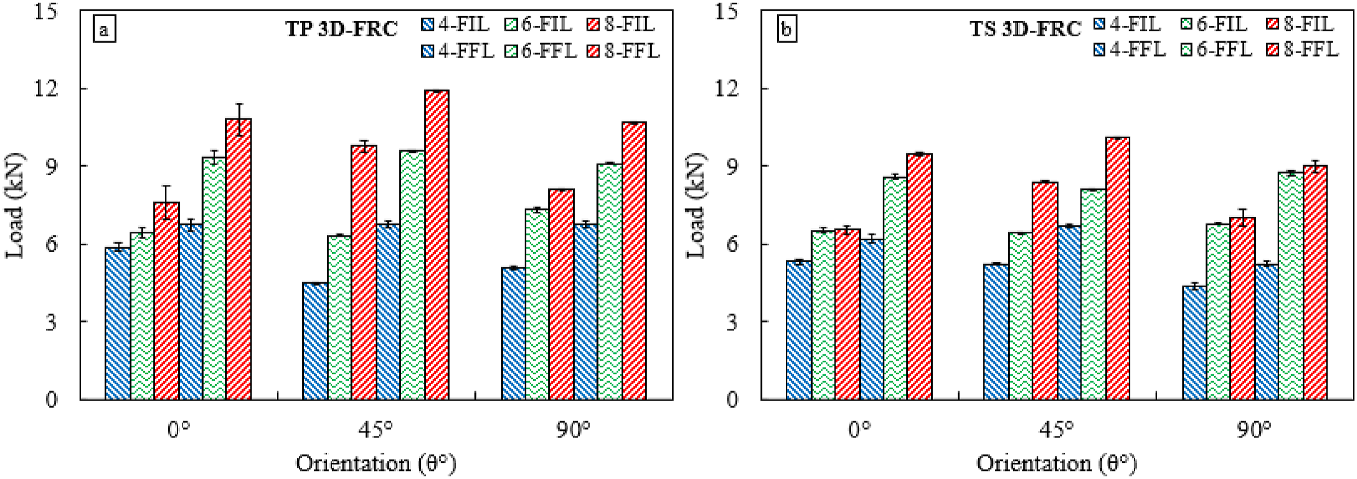
Figure 4(a) depicts a substantial contrast between the initial and final loads in the thermoplastics, indicating considerable damage accumulation before ultimate failure. This damage may involve matrix cracking and yielding, signifying the ability of the joint to absorb a significant amount of energy before complete failure. This capability serves as an early warning signal before catastrophic failure, proving advantageous in safety-critical applications. Figure 4(a) exhibits that the influence of the bolt size in thermoplastic joints is less pronounced than in thermoset joints. This phenomenon can be attributed to the inherent toughness of the thermoplastic matrix. Conversely, a smaller difference in the initial and final loads of the thermosets suggests a more brittle failure, where the damage rapidly propagates after initiation (see Figure 4(b)). The contributing factors may include weak interfaces and poor load distribution. However, a larger difference in resin-infused thermoplastics indicates a more ductile failure, characterized by gradual damage progression before the final rupture.
Comparison of bearing stiffness
In on-axis direction, the thermoplastic lap joints exhibited a uniform bearing stiffness in both directions (0°, 90°), indicating uniform load-bearing capacity regardless of orientation. In contrast, a slight difference in the stiffness of thermoset lap joints is observed in the on-axis direction. This variation in stiffness arises from the localized matrix damage and reduced matrix toughness, which can affect the load transfer and ultimately lead to different stiffnesses in both directions (0°, 90°). In the off-axis direction, SBDS lap joints exhibit similar bearing stiffness behaviour to that observed in the on-axis direction. In comparison, off-axis SBDS lap joints have lower bearing stiffness compared to on-axis joints. This reduction in the stiffness of the off-axis joints is attributed to the applied load, which induces shear stress that can lead to interlaminar delamination and fibre/matrix interface debonding.
The effect of change in bolt size on the bearing stiffness is studied by considering three different bolt sizes 4 mm, 6 mm, and 8 mm for each thermoplastic and thermoset SBDS joint, as shown in Figure 5. The bearing stiffness “k” was calculated within the elastic region of the load-displacement curves, as shown in Figure 3. The bearing stiffness of resin-infused thermoplastics demonstrated a notable increase of 116%, whereas thermoset joints showed a 45% increase with increasing bolt size, as shown in Figure 5(a)-(b). The increase in stiffness is attributed to the larger bolt sizes, which provide a larger contact area between the bolt and the joint, resulting in a more uniform stress distribution and lower local stress concentrations in the material, ultimately leading to lower deformation and higher stiffness. In addition, the matrix toughness also plays an important role in increasing the stiffness of joints with increasing bolt size. The increase in stiffness observed in thermoplastic SBDS lap joints is due to the good adhesion between the fibres and matrix. A strong bond between the fibre and matrix enables effective load transfer and enhances the stiffness of the fibres. Effect of bolt size on the bearing stiffness of SBDS lap joints (a) thermoplastic SBDS joints, and (b) thermoset SBDS joints.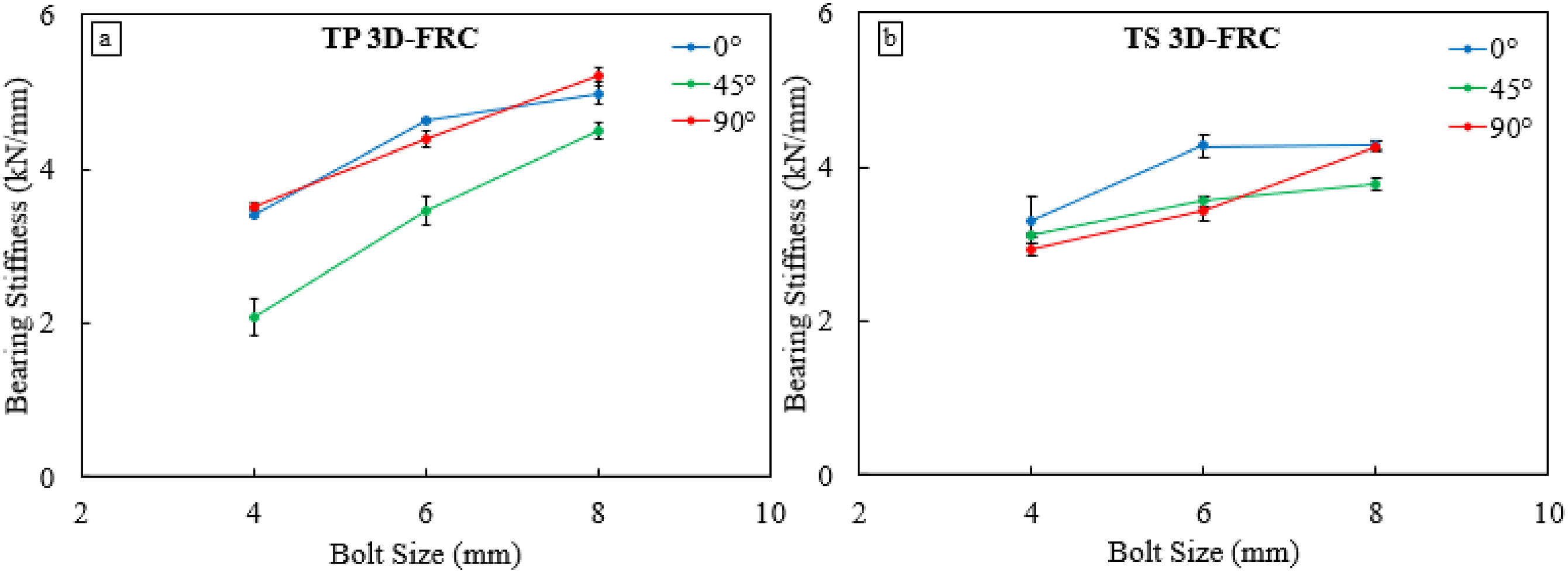
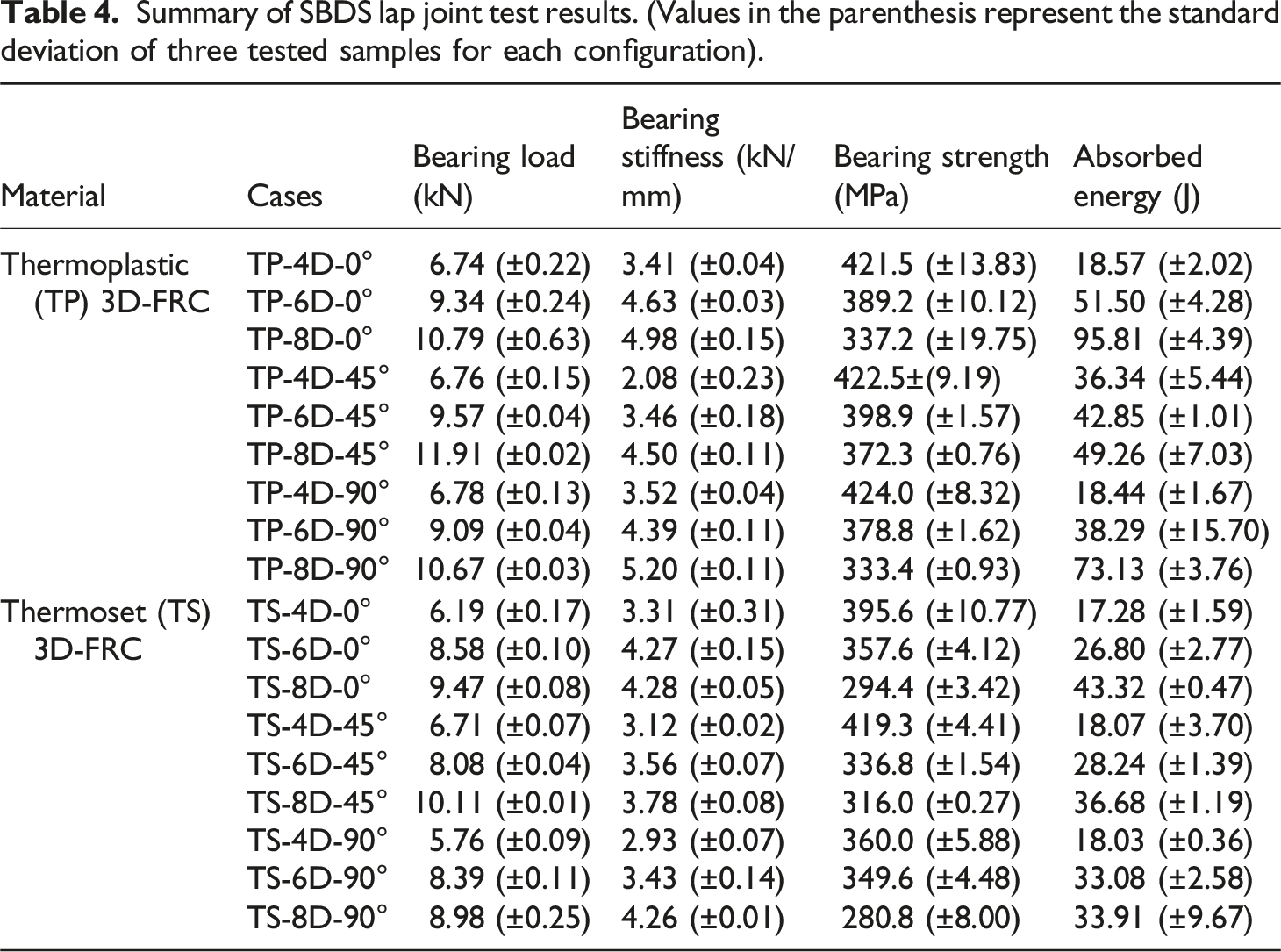
Summary of SBDS lap joint test results. (Values in the parenthesis represent the standard deviation of three tested samples for each configuration).
Comparison of bearing strength
Figure 6 depicts the effect of bolt size on the bearing strength of the resin-infused thermoplastic and thermoset SBDS lap joints. The SBDS joints exhibited a reduction in strength with change in bolt size, which is attributed to the size effect i.e., increasing the size of hole with a fixed width-to-diameter ratio decreases the strength.49,50 Stress concentrations around the edges of larger holes are particularly higher which increases the localized strains within the joint consequently raising the potential of premature failure mechanisms like cracking or yielding. This premature initiation of cracks significantly reduces the bearing strength of 3D-FRCs. With an increase in bolt size, a decrease of 21% was observed in the on-axis thermoplastic joints whereas the thermoset joints exhibited a reduction of 26% in bearing strength (see Figure 6(a)-(b)). Similarly, in the off-axis configuration, resin-infused thermoplastic SBDS lap joints exhibited a 12% reduction in strength compared with a 25% reduction in bearing strength in thermoset lap joints. This study highlights the enhanced bearing strength retention of thermoplastic lap joints compared to their thermoset counterparts owing to their higher matrix toughness. Effect of bolt size on the bearing strength of SBDS lap joints. (a) thermoplastic SBDS joints and, (b) thermoset SBDS joints.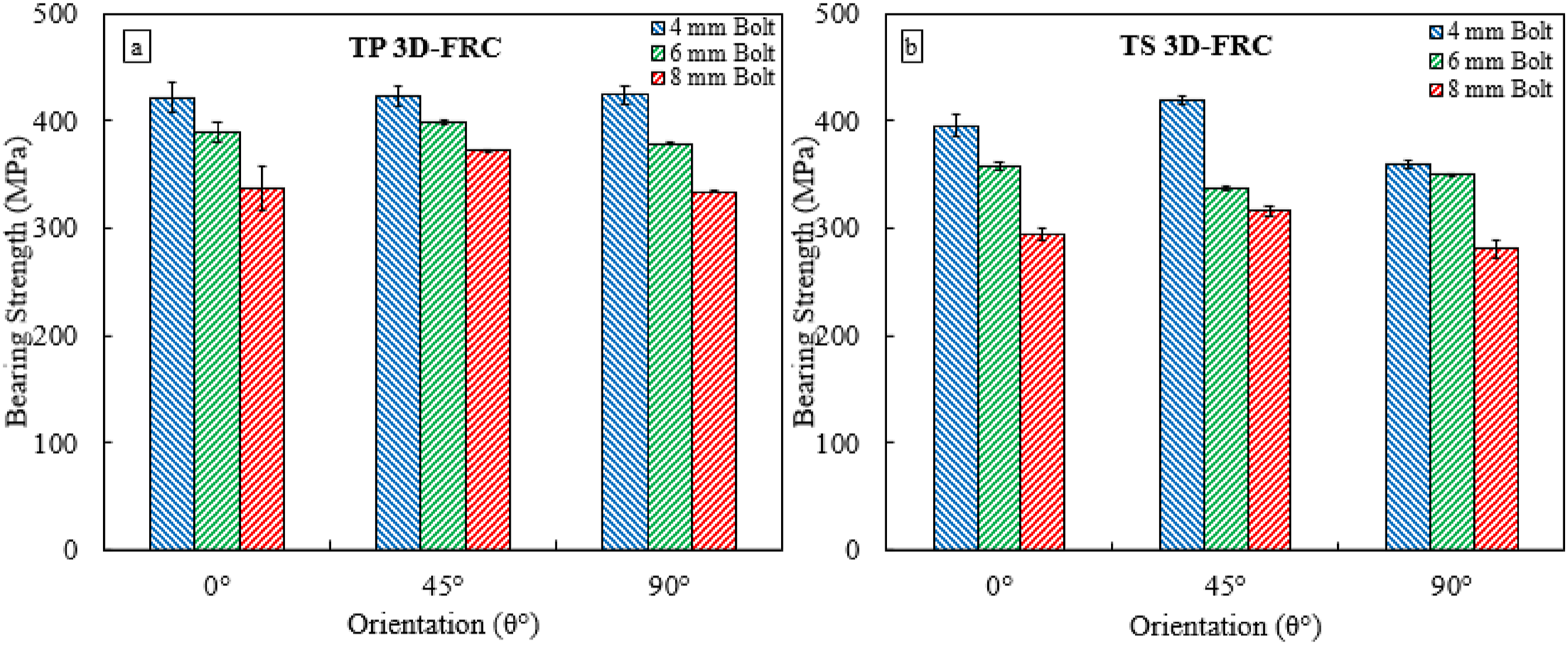
The strength of the joints decreases significantly as the width increases; to mitigate this effect, a constant w/D ratio was used. This constant ratio was intended to minimize the influence of hole size on bearing strength. However, bearing strength remains influenced by hole size as stress concentrations develop around the hole edges, where larger holes result in higher stress concentrations and reduced strength. In contrast, smaller holes distribute stress more uniformly, resulting in higher bearing strength. This phenomenon has been observed in both thermoplastic and thermoset SBDS lap joints. However, due to the higher ductility of the thermoplastic resin, a smaller strength reduction was observed in thermoplastic SBDS lap joints, as shown in Figure 6(a). Additionally, through-thickness tows enhance delamination resistance by reinforcing the laminate layers, which helps maintain structural integrity and improves bearing strength through better load distribution.
Comparison of absorbed energy
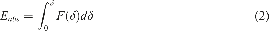
Composites are often subjected to varying loading conditions throughout their service life, including unexpected overloads or impacts. Therefore, the ability to absorb energy before failure is critical. A comparison of the energy absorbed by the thermoplastic and thermoset lap joints before failure is shown in Figure 7(a)-(b). Thermoplastic lap joints absorb more energy compared to thermoset joints owing to the higher ductility and toughness of the matrix. Matrices with higher toughness provide larger deflections, significant plastic deformation, and resistance to debonding by absorbing more energy before failure. The higher energy absorption allows resin-infused thermoplastic joints to resist crack propagation, reduce the risk of catastrophic failure, and increase the overall reliability and safety of structures. With increasing bolt size, an increase of 120% in energy absorption has been observed in thermoplastic lap joints compared to their thermoset counterparts, indicating the higher bearing capacity of resin-infused thermoplastic lap joints. The difference between thermoplastic and thermoset bearings lies in the extent of the damage accumulation. Thermoplastic bearings have a higher damage accumulation than thermoset bearings, which classify thermoplastic lap joints as extensive bearing lap joints. This property allows resin-infused thermoplastic 3D-FRCs to absorb more energy before failure, making them resilient to higher loads. Additionally, this higher damage accumulation in resin-infused thermoplastic joints can provide early warning signals of potential failure, allowing for timely maintenance before catastrophic failure. Comparison of absorbed energy of SBDS lap joints with varying hole sizes (a) thermoplastic SBDS joints and, (b) thermoset SBDS joints.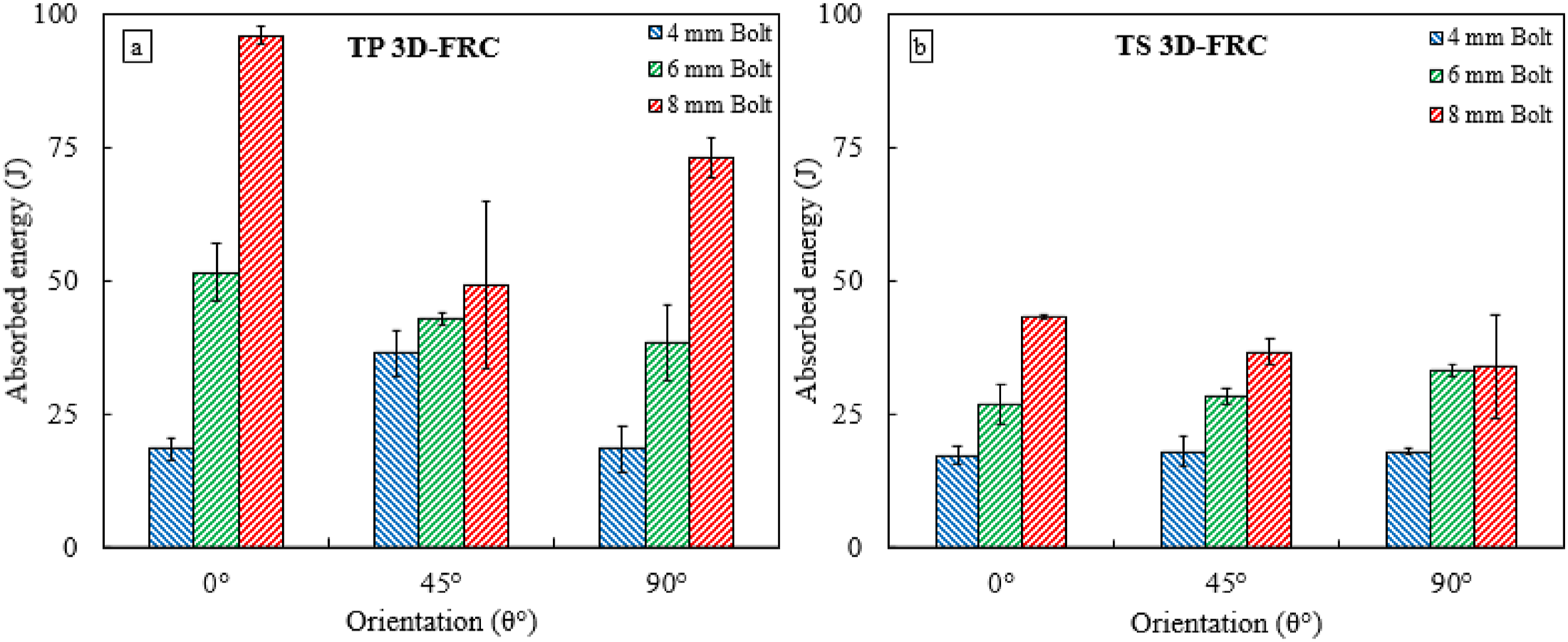
Comparison of damage morphologies of failed specimens
In order to understand the failure behaviour and bearing mechanisms of the SBDS lap joints, the final damage states of resin-infused thermoplastic and thermoset 3D-FRCs were observed, as shown in Figure 8. There was no catastrophic failure experienced by the thermoplastic samples in all the configurations. Thermoplastic 3D-FRC joint experienced severe bearing compared to its thermoset counterparts owing to plastic deformation at the hole front tip. The thermoplastic bolted joint experience matrix yielding at the hole front tip, which reduces stress concentration and causes gradual plastic kinking i.e., plastic deformation and kinking, resulting in reduced damage severity and an overall increase in bearing performance. When a crack develops during matrix yielding, the nearby matrix material undergoes plastic deformation, instead of immediate failure. This absorbs energy, making the crack tip less sharp, and increasing its resistance to further propagation. However, in thermoset 3D-FRCs, matrix microcracking at the front tip of the hole causes fibre breaking, kinking, and increased yarn crushing, which results in increased damage. Furthermore, thermoset 3D-FRCs show evidence of shear-out cracking and normal bearing, whereas resin-infused thermoplastic 3D-FRCs show extensive bearing and plastic deformation on the specimen surface. Ultimate failure patterns of SBDS lap joint at 20% load drop.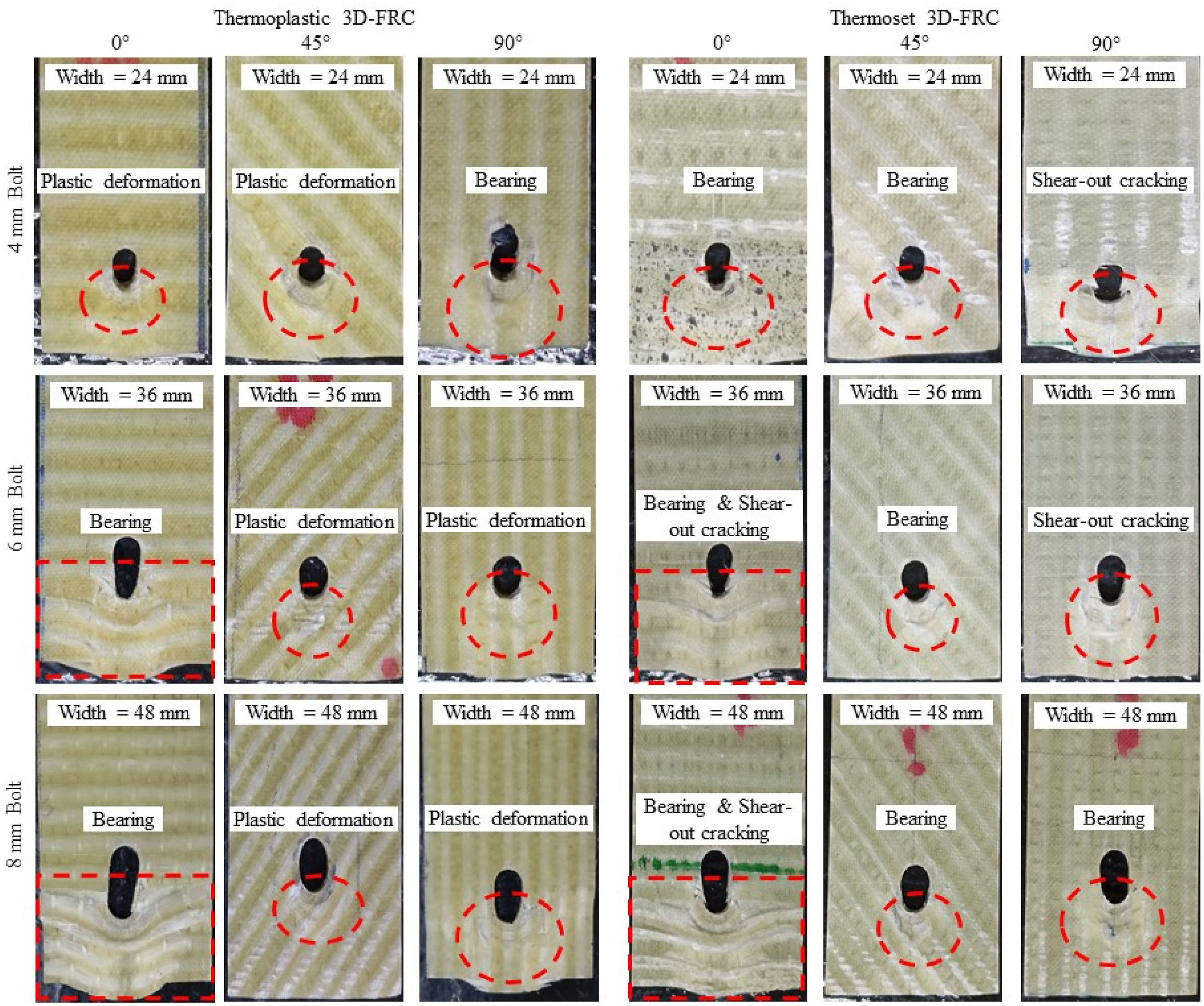
The bearing area of the SBDS lap joints increased with bolt size, as shown in Figure 8. The increase in the bearing area results in a larger contact area between the bolt and 3D-FRCs lap joint. A larger bearing area distributes the load over a larger area, ultimately reducing the stress concentration and minimizing the risk of catastrophic failure due to localized loading. The resin-infused thermoplastic 3D-FRCs bolted joint exhibited unique resistance to damage progression compared to their thermoset counterparts as they experienced extensive bearing, highlighting the ductile behaviour of the polymer matrix. This phenomenon significantly increased the strength of the bolted joints by limiting the damage within the localized region around the bolt hole. The extensive bearing allows the joint to absorb more energy before experiencing failure, as shown in Figure 7, and may potentially prevent a total collapse. The higher damage tolerance of resin-infused thermoplastic 3D-FRCs bolted joints highlights their ability to perform safely under high-bearing loads, where safety is paramount.
Failure mechanisms
In the previous section, it was shown that thermoplastic SBDS lap joints outperformed thermoset joints in terms of damage severity, stiffness, absorbed energy, and bearing strength. The subsequent section will present a comprehensive analysis of the failure mechanisms of SBDS lap joints by using SEM images.
Effect of fibre orientation on the damage characteristics of SBDS lap joints
Figure 9 illustrates the on-axis and off-axis damage characteristics and failure mechanisms of thermoplastic SBDS lap joints. The corresponding SEM images of the damage mechanisms obtained at the final damage state i.e., 20% load drop from the ultimate bearing load are shown in Figure 9(a)–(i). The failure modes identified in thermoplastic 3D-FRCs joint were bearing failure, followed by matrix plastic deformation and plastic kinking. In 3D-FRCs, when the applied load exceeds the bearing capacity of the joint, localized deformation of the material occurs. This localized deformation eventually causes matrix plastic deformation and plastic kinking in the joints around the bolt hole. When loaded, the matrix material around the bolt hole undergoes plastic deformation, resulting in the formation of kinks in the fibre. This fibre/matrix interaction creates localized kinks in the material, called plastic kinking, as shown in Figure 9(b), (c) and (g)–(i). SEM images of microscopic damage mechanisms in thermoplastic SBDS lap joints with varying orientation. (a)–(c) final damages in 0° thermoplastic 3D-FRCs; (d)–(f) final damages in 45° thermoplastic 3D-FRCs; and (g)–(i) final damages in 90° thermoplastic 3D-FRCs.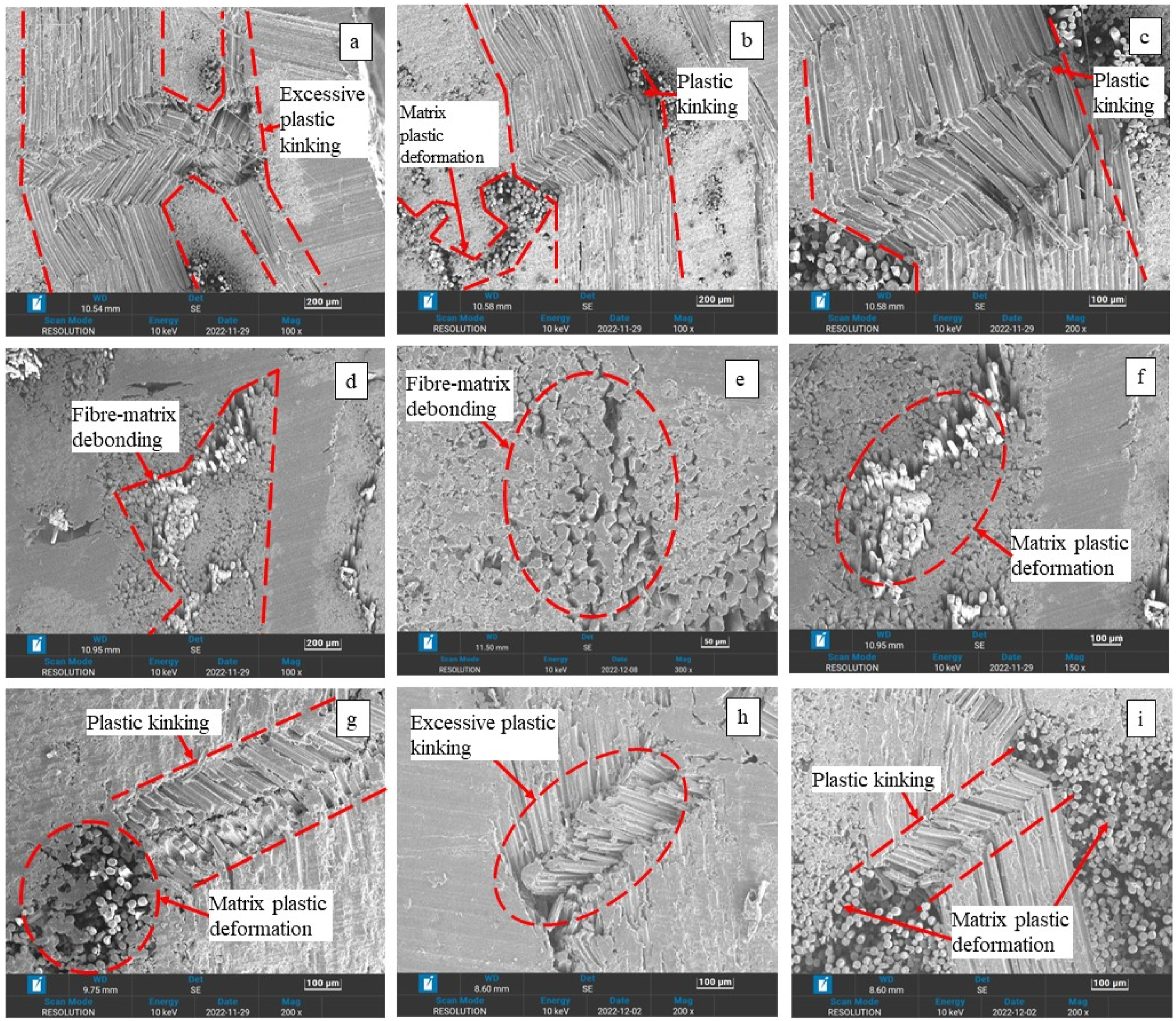
In on-axis SBDS lap joints, when the applied load exceeds the ultimate bearing load of 3D-FRCs joint, plastic deformation, and plastic kinking are the observed failure mechanisms as shown in Figure 9(a)–(c) and (g)–(i). Conversely, in off-axis joints, fibre/matrix debonding and plastic deformation are the predominant failure mechanisms as shown in Figure 9(d)–(f). The cause of these failure mechanisms in off-axis joints is mainly due to the stresses generated at the fibre/matrix interface, a phenomenon that does not occur in on-axis joints. Overall, in thermoplastic 3D-FRCs lap joints, the primary failure mechanisms are plastic deformation, plastic kinking, and fibre/matrix interface debonding initiated by the compressive load applied by the bolt, resulting in extensive bearing failure of the SBDS lap joints.
Damage characteristics and failure morphologies of the on-axis and off-axis thermoset SBDS lap joints are shown in Figure 10. Thermoset lap joints experienced more severe damage including bearing failure and shear-out cracking followed by fibre crushing, transverse matrix cracking, fibre/matrix interface debonding, and fibre kinking. The increased damage observed in thermoset SBDS lap joints compared to thermoplastic counterparts may be attributed to the higher brittleness and lower toughness of the thermoset matrix. The SEM images shown in Figure 10(a)–(i) were obtained at the final damage state (20% load drop from ultimate bearing load). In on-axis 3D-FRCs joint, matrix cracks lead to extreme fibre kinking and fibre crushing in the yarns resulting in fibre breakage, as shown in Figure 10(b)-(c), (g)–(i). Whereas in the off-axis 3D-FRCs joint, severe matrix crushing, fibre/matrix debonding, and matrix cracking cause the buckling of the yarn due to compressive load applied by the bolt as shown in Figure 10(d)–(f). Due to lower matrix toughness, multiple transverse cracks and matrix debonding occurred in thermoset lap joints, resulting in lower bearing strength. SEM images of microscopic damage mechanisms in thermoset SBDS lap joints with varying orientation. (a–c) final damages in 0° thermoset 3D-FRCs; (d–f) final damages in 45° thermoset 3D-FRCs; and (g–i) final damages in 90° thermoset 3D-FRCs.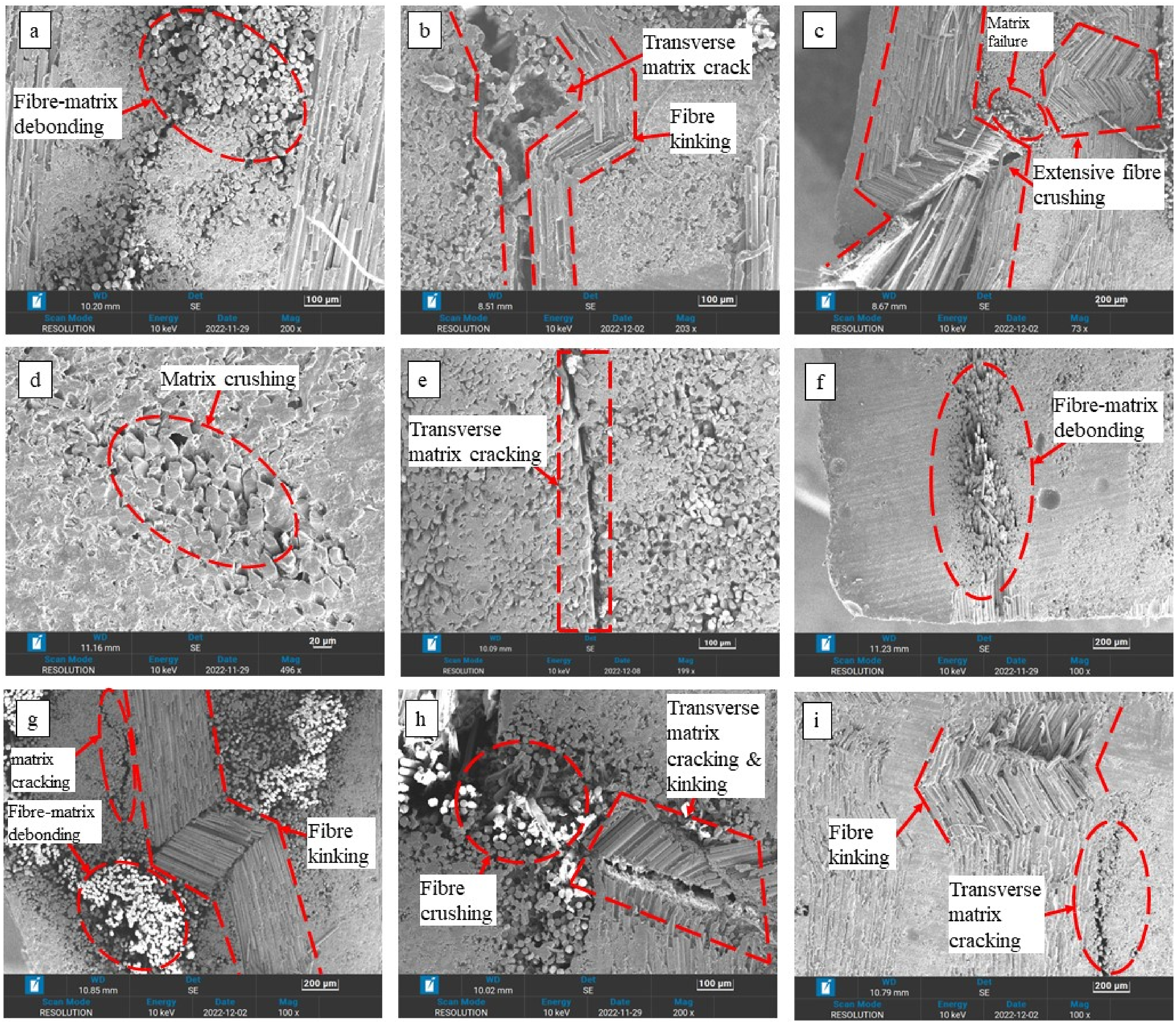
A detailed investigation of the behaviour of on-axis and off-axis SBDS lap joints has been conducted. The primary failure mechanisms in thermoplastic 3D-FRCs joints are coupled matrix plastic deformation and plastic kinking initiated under bolt compressive loading that results in the bearing failure of SBDS lap joints. While, in thermoset 3D-FRCs joint, bearing failure initiates kinking causing fibre breakage which further leads to fibre crushing under compressive loads. A notable observation, when comparing Figures 9 and 10 is the extensive fibre-matrix debonding in thermoset-based joints. In addition, wide cracks were observed at several locations in the thermoset-based samples, indicating the weak interface strength and brittle nature of the thermoset resin. Another significant failure phenomenon in thermoset-based joints is the extensive fibre crushing, which is not present in thermoplastic-based joints. In contrast, thermoplastic joints exhibited minimal fibre-matrix debonding at a few locations and no widely opened cracks. These failures show the higher fibre-matrix interface strength and matrix-yielding capability of thermoplastic joints.
Effect of bolt size on the damage characteristics of SBDS lap joints
The larger bolt in SBDS lap joints primarily increases the bearing area and results in a larger contact area between the bolt and 3D-FRCs lap joint. In 3D-FRCs, bolt pressure initiates plastic deformation of the matrix, reducing stress concentration, resulting in lower damage severity, and ultimately affecting the bearing performance of the joints. The larger bolt sizes in fibre reinforced SBDS lap joints result in a reduction in bearing strength caused by increasing damage area. The damage characteristics and failure mechanisms of thermoplastic SBDS lap joints with varying hole sizes are shown in Figure 11. It can be seen in Figure 11 that the damage severity increases with bolt size. Figure 11(a)–(e) shows damage mechanisms of joints with 4 mm bolt size. The most common failures encountered in thermoplastic lap joints with smaller bolt sizes are fibre kinking, plastic deformation, and fibre-matrix debonding. As the bolt size increased, thermoplastic lap joints experienced more severe bearing failure with failure mechanisms such as excessive plastic kinking and fibre matrix debonding as shown in Figure 11(f)–(i), resulting in lower bearing strength of joints. SEM images of microscopic damage mechanisms in thermoplastic SBDS lap joints with varying bolt sizes. (a–e) final damages in 4 mm bolt size in thermoplastic 3D-FRCs; (f–i) final damages in 8 mm bolt size in thermoplastic 3D-FRCs.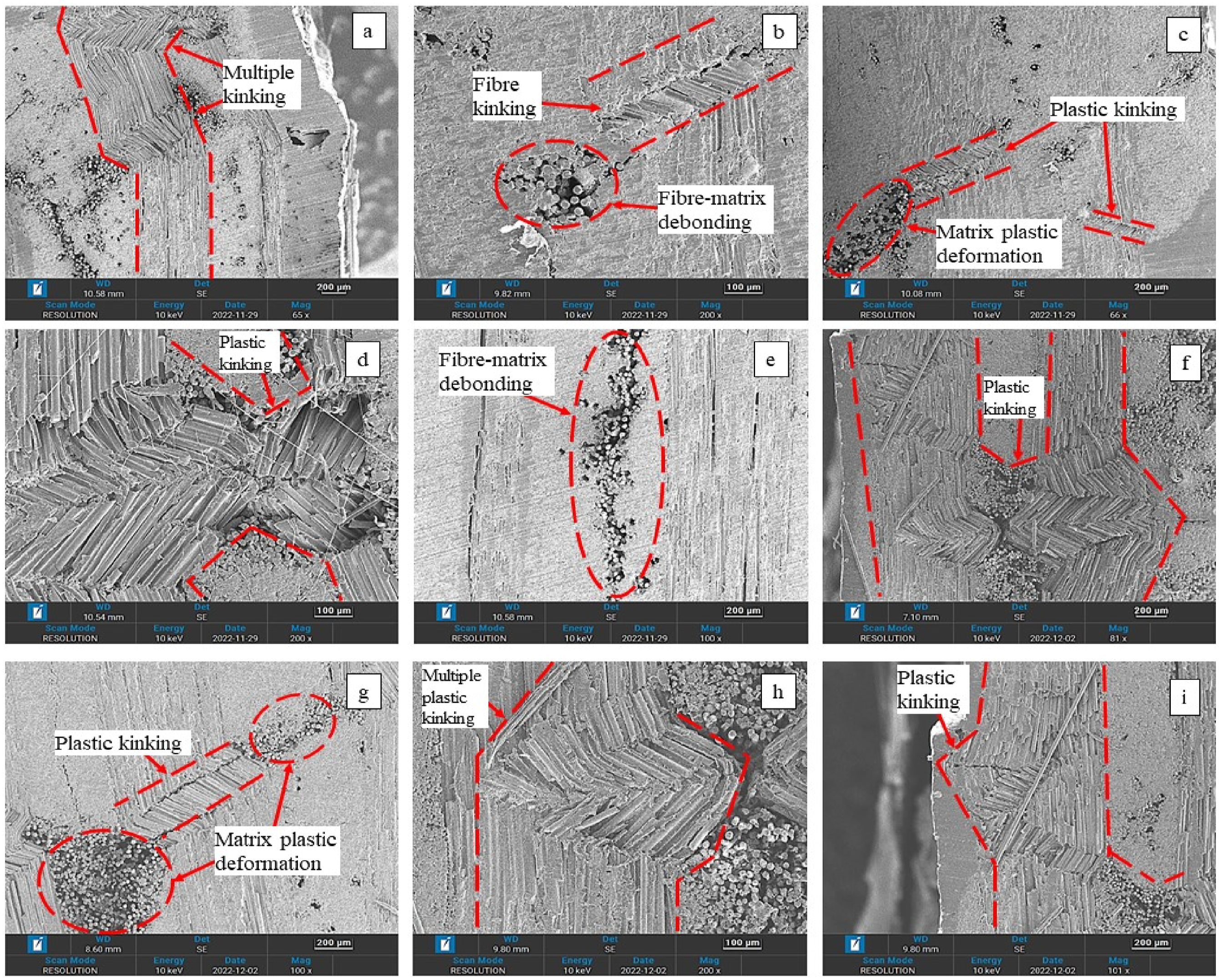
The thermoset SBDS lap joints have a higher damage severity compared to the thermoplastic SBDS lap joints. Figure 12 shows the cross-section of the bearing plane of thermoset lap joints with varying bolt sizes. As the bolt size increased, thermoset lap joints exhibited a similar bearing failure pattern compared to their thermoplastic counterparts. The final damage state of joints with smaller bolt size (4 mm bolt) showed transverse matrix cracking, fibre/matrix debonding, and fibre brooming as shown in Figure 12(a)–(d). Damage severity in lap joints increases with bolt size, and thermoset lap joints experienced excessive fibre kinking, fibre brooming, and severe fibre/matrix interface debonding as shown in Figure 12(e)–(i). Thermoset lap joints exhibited more severe failure compared to thermoplastic lap joints due to higher brittleness and lower toughness. SEM images of microscopic damage mechanisms in thermoset SBDS lap joints with varying bolt size. (a)–(d) final damages in 4 mm bolt size in thermoset 3D-FRCs; (e)–(i) final damages in 8 mm bolt size in thermoset 3D-FRCs.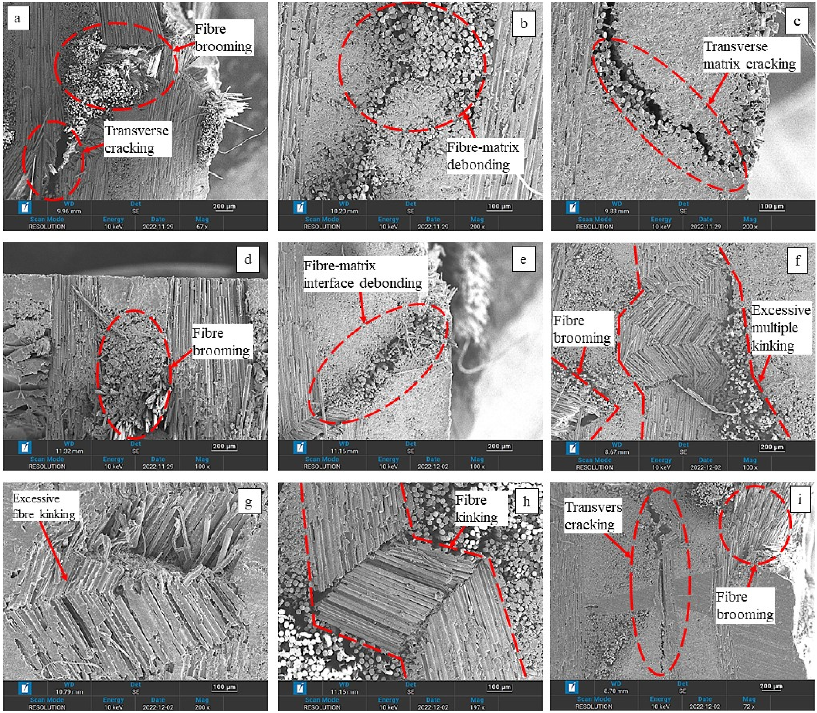
Conclusion
An experimental study on the bearing performance of resin-infused thermoplastic and thermoset 3D-FRCs in on-axis and off-axis configurations has been presented. This study involves the investigation of bearing performance including bearing strength, stiffness, failure initiation and final failure load, absorbed energy, and damage morphologies of 3D-FRCs obtained from SEM images. Both thermoset and resin-infused thermoplastic 3D-FRCs exhibited a linear elastic response to the onset of failure, followed by a nonlinear shear response until failure. In SBDS lap joints, bolt size significantly affects the bearing strength of structures. In on-axis configuration, resin-infused thermoplastic observed 21% reduction in strength whereas thermoset experienced 26% reduction in bearing strength. Similarly, in off-axis configuration, thermoplastic observed 12% reduction while thermoset observed 25% reduction in bearing strength. This reduction in bearing strength is attributed to the hole size effect. In on-axis configuration thermoplastic and thermoset joints exhibit similar bearing stiffness. An increase of 46% and 48% in stiffness of thermoset and thermoplastic 3D-FRCs is observed. However, in off-axis configuration, a significant increase of 116% in the stiffness of resin-infused thermoplastic SBDS lap joints has been observed. The increase in bearing stiffness is mainly due to the higher matrix toughness and stronger interface of the thermoplastic matrix. Thermoplastic lap joints absorb more energy compared to thermoset joints, highlighting that matrix toughness plays a significant role in improving joint performance. Thermoplastic lap joints absorb 120% more energy compared to thermoset counterparts, indicating that matrices with higher toughness allow larger deflection, resist debonding, and absorb more energy before failure. The failure mechanism study of SBDS lap joints revealed that resin infused thermoplastic SBDS lap joints experienced plastic kinking resulting in severe bearing without any catastrophic failure, whereas thermoset joints experienced transverse cracking, fibre/matrix debonding, and fibre brooming resulting in shear out cracking. Overall, thermoplastic SBDS lap joints show better response (bearing strength, bearing stiffness, load bearing, and damage characteristics) as compared to thermosets establishing their suitability for higher bearing strength applications. The comparison of damage response and failure mechanisms of SBDS lap joints with finite element simulations will be presented in the future publication.
Footnotes
Declaration of conflicting interests
The author(s) declared no potential conflicts of interest with respect to the research, authorship, and/or publication of this article.
Funding
The author(s) disclosed receipt of the following financial support for the research, authorship, and/or publication of this article: The authors would like to acknowledge the financial support provided by Universiti Teknologi PETRONAS (Grant number 015LC0-351).